BACKLIGHTING SURFACES - C2 202 GHT TAPE ELECTRO-LUMINX LIGHTING CORPORATION - 2021 LIGHT TAPE ELECTRO-LUMINX LIGHTING CORPORATION
←
→
Page content transcription
If your browser does not render page correctly, please read the page content below
©202 ght Tape® Electro-LuminX Lighting Corporation• C2

    Backlighting
    Surfaces

©2021 Light Tape® Electro-LuminX Lighting Corporation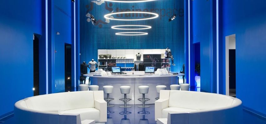
©2021 Light Tape® Electro-LuminX Lighting Corporation

United States
(Headquarters)
1320 N. Arthur Ashe Boulevard
Richmond, VA 23230
Tel: 804 355 1692
thelighttapeteam@lighttape.com

                                    Europe
Australia                           James Earle
27 Jones Street, O’Connor Western   Business Development Leader
Australia, 6163                     Tel: +44 7503 609035
Tel: (08) 9337 5217                 europe@lighttape.com                 India
australia@lighttape.com                                                  75/6, Shipra Path,
                                                                         Mansarover Jaipur (Rajasthan)
                                                                         INDIA
                                                                         Tel: +91 9829056623
                                                                         india@lighttape.com
                                    South America
South Africa                        Cra. 5A No. 2Sur-45, CA12
1st Ave East Parktown North         Chia, Cundinamarca – Colombia, Sur
The Warehouse Unit 3, JHB 2193      America
Tel: 011 447 9709                   Tel: 313 819 2209
southafrica@lighttape.com           southamerica@lighttape.com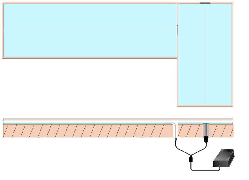
©202 Light
©2021       Tape®Electro-LuminX
       ght Tape® Electro-LuminXLighting
                                Lighting Corporation
                                         Corporation
                                                   • C2

    Table of Contents
    Backlighting Surfaces
    A6. Light Tape® Standard Sizes
    A8. Color Options
    C4. Backlighting Materials: Top View
    C5. Backlighting Custom Shapes
    D2. Light Tape® Safety & Handling
    D3. Indoor Installation
    D4. Installing Panels for Backlighting
©2021 Light Tape® Electro-LuminX Lighting Corporation • A6

           Light Tape® Standard Sizes
                                                                                                 WHEN ORDERING, PLEASE SPECIFY:
                                                Laminated Width          Laminated Width
     Item No. Illuminated Width                    (Interior)               (Exterior)           • Installation location - Interior (INT) or Exterior
                                                                                                 (EXT)
       LT-050         0.5”         12.7mm        0.75”     19.05mm            1”      25.4mm

       LT-100          1”         25.4mm         1.25”     31.75mm           1.5”     38mm       • Desired illuminated color
       LT-200          2”          50.8mm        2.25”      57.15mm          2.5”     63.5mm
                                                                                                 • Illuminated width item number
       LT-400           4”         101.6mm       4.25”     107.95mm          4.5”     114.3mm
                                                                                                 • What length for each Light Tape® lamp? (min
       LT-600          6”         152.4mm        6.25”     158.75mm          6.5”     165.1mm
                                                                                                 order length of 25 ft / 7.62m required)
       LT-1200         12”        304.8mm        12.25”     311.15mm         12.5”    317.5mm
                                                                                                 • Total number of lamps required
      LT-3000          30”         762mm        30.25”     768.35mm       30.5”       774.7mm
                                                                                                 • Power Input - AC or DC? What input voltage?
                             Please note: Custom widths available to order
                                                                                                 • Flexible extension connection tabs for
                                                                                                 backlighting applications are standard at 4”
                                                   Laminated width                               long. This allows connector to be hidden. Please
                                                  Illuminated width                              advise if longer lengths are required.
   TOP VIEW

                                                                                                 ADDITIONAL INFORMATION:
                                                                                                 • Custom widths are possible to fit any
                                                                                                 dimensions. Light Tape® can be tiled together
                                                                                                 with no seams or gaps in illumination.

 Split Electrode                                                                                 • Power input location (please specify short or
       Midpoint                                                                                  long side of lamp).
                                                                                                 • A basic top or front view drawing with
                                                                                                 dimensions is helpful to our engineering team
                                                                                                 to estimate materials needed.
0.125” (3.175mm)
                                                                                                 • We will suggest best electrical configurations
     Clear Barier
  Encapsulation                                                                                  for your project based on site layout.
                                                                  Standard 4” (101.6mm)
                                                                  Flexible Extended Connection
                                                                  Tab

   NOTE: the split electrode midpoint (SEMP) is a critical element of Light Tape®’s
   engineering that runs centered through the entire length.
©2021 Light Tape® Electro-LuminX Lighting Corporation • A8
Light Tape® Color Options
Our base colors are the Classic Natural Blue and Extreme
Blue-Green. These colors appear white when off and lightly colored when
illuminated. We then add filters to produce alternative color options.
Our Media White and Glacier White colors are perfect for backlighting
and applications requiring white, unfiltered light, these will appear lightly
colored when switched off.
Our remaining range of colors will retain their vibrance when not
illuminated so you don’t lose the desired effect even when it’s switched
off, perfect for branding and advertising.
CLASSIC SERIES
Natural Blue Media White Glacier White Yellow
Off On Off On Off On Off On
Electric Blue Rich Red
Off On Off On
EXTREME SERIES
Blue Green Caribbean Blue Purple Orange
Off On Off On Off On Off On
Rich Red International Red Pink Green
Off On Off On Off On Off On
NOTE: The colors in this guide are simulated and as such the final product may vary. If an exact color is required, we recommend
seeing a physical sample of the lamp. Custom colors and widths are available, but may be subject to minimum order quantities,
set-up fees, and approval testing.©2021 Light Tape® Electro-LuminX Lighting Corporation • D2
©2018 Light Tape® Electro-LuminX Lighting Corporation • C2
Light Tape® Safety & Handling
Safety: General Installation Guidelines:
• Never power on and leave Light Tape® in a coil. Unroll first • Follow all installation guidelines from Electro-LuminX.
before switching on. Please visit our website www.lighttape.com for additional
• Always consult local electrical codes for wiring regulations information.
and installation requirements. • Please read all instructions prior to installation. Contact
• Light Tape® should be covered with a protective overlay if your regions tech support with any questions.
installed within direct reach of the general public. • When unpacking, please review all contents on the packing
list and immediately notify us of any missing or damaged
• Always seal Light Tape® lamp with Edge Guard™ end seal
items.
tape when cut. Exterior rated Light Tape® must only be
cut and sealed in factory. • There is a front and back of Light Tape®. The gray colored
side with a white line down the middle is the back, and
• Do not make electrical connections when Light Tape® is non-illuminating side.
turned on.
• Do not mount using an epoxy, silicone, or other exothermic
• Do not operate Light Tape® without protective insulating curing adhesives, as they may damage the conductive
lamination due to risk of shock. Install in dry conditions. layers. We recommend 3M double sided tapes. Please
Do not cut or expose open ends to moisture. contact us for additional information.
• Smart Driver™ power supplies are equipped with overload • If mounting near a wet area, please provide suitable
and short circuit protection. If trip occurs during operation, protection from pooling water. Ensure there are no
please inspect Light Tape® for damage, and operating standing water conditions, and provisions for drainage are
voltage is within correct range. made.
• Do not operate your Smart Driver™ outdoors unless in • Light Tape® can be mounted outdoors, however should not
a suitably rated enclosure. Ensure installation in a dry be operated in direct sunlight. This will shorten the life of
environment. the lamp. Use a photo-cell to prevent the Light Tape® from
Handling: operating in peak daylight hours.
• Do not step on Light Tape® during installation. Keep • Always mount in extrusion or approved system for outdoor
Light Tape® off the floor or any rough surfaces during installations. It is important to allow for the thermal
installation. expansion coefficients of exterior surfaces. Both sides
of Light Tape® must remain free to move with changing
• Do not pull on the connector and/or Tab when installing or ambient temperatures.
removing.
• Do not mount Light Tape® or Smart Driver™ directly to
• Only install in dry conditions. Do not cut or expose open resonant surfaces such as metal, as this may produce
ends to moisture. amplified harmonics. We recommend mounting to a cork,
• Take care to not damage lamination when installing around or foam layer completely covering the subsurface.
sharp edges or corners. Avoid the use of any sharp objects • Light Tape® is non-polar, each hemisphere requires its own
to force lamp into tight areas. lead from the power supply. Multiple Light Tape® pieces
• Avoid any hard creases. Do not fold, twist, rotate, or kink must be installed in parallel.
lamination excessively. • The Smart Driver™ to be selected based on total load. One
• Do not stretch, puncture, or hard crease Light Tape® in a Smart Driver™ can light multiple Light Tape® pieces. Do
tight radius, as this will destroy conductive layers causing not under load or over load the Smart Driver™
black spots or failure. • Do not power up the Smart Driver™ without having the
• Do not operate lamp outdoors during peak daylight hours proper load applied.
for extended periods as it may be damaged by UV rays. • The Smart Driver™ should be set to 270V AC output. This
• Do not thermoform or stretch Light Tape® over objects. will help maximize lifetime of the lamp.
• When cleaning Light Tape® or Smart Driver™, do not use • Always mount the Smart Driver™ vertically (with the
water or chemical cleaners. fan facing up) if the model has a fan to allow proper air
circulation.
• Do not staple or puncture through Light Tape® or the
protective lamination. Take care around screw heads or • Always store electronics in dust free environments to
other sharp protruding objects. ensure proper performance.©2021 Light Tape® Electro-LuminX Lighting Corporation • C4
Backlighting Materials: Top View
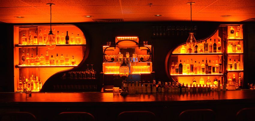
BASIC BAR, COUNTER TOP OR WALL
Any surface area can be evenly illuminated with a minimal number of panels and connections. A bar design
resembling the one below would require only two Light Tape® panels and one power supply. The Light Tape®
panel is placed directly on surface with double sided adhesive.
TOP VIEW
72” (1,828.8mm) 30” (609.6mm)
Connection
Locations
30” (609.6mm) LT-A
LT-B 48” (1,219.2mm)
Example Product Breakout:
• 2 LT Panels: LT-A (30” x 72”) + LT-B (30” x 48”) = 2,880 in2 or 18,453 cm2
• 2 LT Connections w/ 4” (101.6mm) extension tabs
• 1 DSD 4000 (Power Supply/Inverter)
CROSS SECTION
LT-A LT-B
Extension tabs make a seamless illumination possible.
See Installing Panels for Backlighting sheet (D4) for more information.
SURFACE WITH CUT OUTS
Light Tape® panels can be custom cut to any shape and placed side-by-side or overlapped to seamlessly
illuminate any surface. For custom shapes, an AI file or template will need to be provided.
150” (3810mm)
__ø
LT-A LT-D
24”
(609.6mm) Connection
Locations
LT-B LT-E
LT-C
60” (1,524mm) 30” (762mm) 60” (1,524mm)
Example Product Breakout:
• 4 LT Panels: LT-A, LT-B, LT-C, LT-D (4)(12”x 60”) = 3600 in2 or 9144 cm2
• 1 LT Custom Panel LT-C (30”x 24”) - (12”x24” cutout) = 288 in2 or 731.52cm2
• 5 LT Connections w/ 4” (101.6mm) extension tabs
• 1 DMX 4000 (total 3,312 in2 )
Please note: accurate dimensions for cutouts are required for all custom cut
panels©2021 Light Tape® Electro-LuminX Lighting Corporation • C5 ©2018 Light Tape® Electro-LuminX Lighting Corporation • C2 Backlighting Custom Shapes Light Tape® can be cut into just about any shape and size whilst maintaining its uniform illumination. No shape is impossible to illuminate, regardless of the size. This makes Light Tape® the most versatile lamp in the world, suitable for any kind of bespoke design. SYMMETRICAL SHAPES Both hemispheres need to be equal in surface area to ensure that Light Tape® illuminates evenly. Symmetrical shapes such as the one shown are easilly produced, with the SEMP (split electrode midpoint) dividing the shape into two equal hemispheres. ASYMMETRICAL SHAPES Creating a custom shaped light source would usually be a daunting process, but with Light Tape®, bespoke lighting has never been easier. For Asymmetrical shapes, we require an Adobe illustrator or PDF file to be submitted with your design. From this file, we can determine the total surface area of your shape and place the SEMP so that the shape is divided into two equal hemispheres. If you do not have an AI file for your shape, it is possible for our team to create one for you. In this case, simply provide a template of your shape, and we can do the rest. CUSTOM SHAPES ORDERING PROCEDURE: Do you have a curved or oval counter top, cut outs for sinks, faucets, stanchion holes for mounting, or shapes that can be classified as non-rectangular? If so, please prepare a .plt, .dwg, or .ai file. The file should be the exact size the client would like the Light Tape® lamp cut excluding lamination. Please scale the file down by .25” to account for 1/8” lamination trim on all sides. Files must be reduced to illuminated area, reducing capacity for error. If you prefer, we can accept two files – one for lit area, and one for the finished size. Following the receipt of your file, our production team will create a physical template from the file submitted on a plastic film. We will ship this to you for approval. Please note that there will be an additional 1/8” laminate border surrounding the final illuminated Light Tape® panel. Once the plastic template is approved, your order will be produced.
©2021 Light Tape® Electro-LuminX Lighting Corporation • D3

     Indoor Installation Tips

1. Clean surface with isopropyl alcohol to remove all dust, oil and grease. Surface should be smooth and
    clean for strong adhesion.
2. Determine where you will make the electrical connection. It is important to consider the connector and
    cap lengths. The conductive electrodes can be located behind the Light Tape®. We recommend all
    electrical connections are made in a suitably rated junction box. Always consult local electrical codes
    for wiring regulations and installation requirements.
3. Mount in a manner that allows the LightTape® to be easily serviced (i.e. wall studs behind sheet rock
    wall). Do not step on Light Tape® during installation. Avoid hard creases. We recommend using our
    VibraMount™ adhesive as a backing when indoors. Place adhesive on wall, trim to size if needed, and
    remove liner.
4. Hide the connector. The conductive electrodes are essently flat conductors. Be care not to rip the
    surrounding lamination around the lamp; lamination can be trimmed around the tabs if needed.
    Ensure a sufficient lamination border surrounding the connection tabs.
5. Be very careful when applying Light Tape®, make sure the coiled lamp is straight before you start to
    unroll. Once it has been applied, pulling Light Tape® off without care may damage the lamp.
Please note:
For larger panels, it is easier to unroll the Light Tape® into place. Begin with the connector end, make sure
the leading edge is square, and slowly unroll the panel into position.

Remote Power Supply Installation
Sometimes, the power supply must be located far from the lamps. In this case, shielded conduit may be
required to protect against high frequency and high voltage.
• A suitably rated enclosure is required to store power supply when located outdoors to ensure
   protection against the elements.
• 50 foot connection radius - it is possible to install the Light Tape® up to 50 feet (15.25m) from the
   Smart Driver™ Power Supply. Multiple connections are possible from one central location.
• Electrical Metallic Tubing (EMT) conduit is required to shield the high voltage and high frequency AC
   signals for remote installations. All wiring should be within a conduit and 600 volt rated.
• Always consult local electrical codes for wiring regulations and installation requirements.
©2021 Light Tape® Electro-LuminX Lighting Corporation • D4
Installing
Panels for Backlighting
It is important to consider the following when installing large panels for backlighting
• Light Tape® panels utilized for backlighting are equipped with extension tabs. The tabs are designed to position the
electrical connection under the mounting surface.
• Light Tape® panels do not have polarity (+ or -)
• Multiple panels, connected in parallel, can be powered by a single Smart Driver™ lighting ballast.
• Do not crease or hard fold Light Tape®, keep out of work area until ready to install. Ensure it is placed on a clean,
smooth surface.
• Plan panel placement before adhering to surface with foam adhesive panels.
• Do not mount Light Tape® or Smart Driver™ directly to resonant surfaces such as metal, as this may produce
amplified harmonics. Please note, audible harmonics will be minimised once Light Tape is secured and installation
is complete.
• In many cases, very little adhesive is necessary to hold light tape® in position. Please note, LightTape® is designed
for compressive loading only, tensional and shear loads must be avoided.
1. To test the backlighting layout, lay the Light Tape®
panels on the surface of the substructure. Adjust the The 0.25” (6.35mm) Clear
placement of the Light Tape® panels to make sure the Barrier
entire surface area is covered and there are no seams. Encapsulation envelops
It is acceptable for the Light Tape® panels to overlap if the illuminated panel on
necessary, to maintain light uniformity. all four sides.
2. Once preliminary test layout is complete, identify the
position of any clearance cutouts required to conceal the
connector into the substructure. Then remove all Light
Tape® panels prior to creating the cutout/s.
3. Remove release paper from one side of the foam
adhesive and adhere into place on the subsurface.
4. Feed the connectors and leads through the cutouts and
connect all leads in parallel to the Smart Driver™ power Flexible extended connection tabs
supply. The Light Tape® panels utilized for backlighting to facilitate installation. Standard
are equipped with flexible extension tabs to allow for tab is 4” (101.6mm).
concealed connections.
5. Peel off release paper from the other side of the foam
adhesive.
6. Making sure to replicate preliminary layout, begin to
mount the Light Tape® panels. Starting with connector
end, unroll panel in a straight path being careful to avoid
bumps or ridges, ensuring the Light Tape® is flat to the
surface.
7. Once first panel is set in place, continue placing panels Flexible extended connection
one by one until surface is covered, overlapping adjoining tabs allow the connector to be
panels to cover entire surface area. hidden or countersunk.
8. Test operation of the Light Tape® panels once all are
installed and connected to corresponding power supplies
prior to installation of the final backlit surface.WWW.LIGHTTAPE.COM
V2.0.1
©2021 Light Tape® Electro-LuminX Lighting CorporationYou can also read