Extending a 2D Zone of Influence to 3D using Oracle 10g and 11g SDO_TIN - The SpatialDB Advisor
←
→
Page content transcription
If your browser does not render page correctly, please read the page content below
Extending a 2D Zone of Influence to
3D using Oracle 10g and 11g SDO_TIN

                       Simon Greener,
                       The SpatialDB
                             Advisor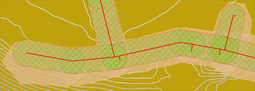
Reiterating what has gone before...
The Business Problem

 • Policy to be implemented

    Title:        Building Near Water and Sewer Services

    MCW Ref:      64752

    Date of Issue: 16 July 2003

    Prepared by: Design and Construction Branch
Policy

      • Mid Coast Water:
           – “... will not give approval for structures ...
             built over a sewer rising main or water
             main ... within distances specified in this
             policy [where easement* does not exist]”
             (similarly for gravity sewers);
           – “...may approve structures ... built adjacent to
             a sewer, a sewer rising main or a water main
             providing precautions are taken with the
             design of the footings”

* Presentation assumes all pipes do not have easements.
Policy Aim
• Policy aimed at:
– Preventing structure damage to pipes.
– Preventing damage (eg subsidence) to buildings.
– Maintaining access to manholes, junctions and
inspection shafts;
– Enable efficient and economical access to
pipework for major repairs or replacement;
– Reduce future maintenance costs;
– Provide a consistent approach to building over
or near underground pipework throughout the
area of operations.Policy Application and Scope
• Application
– “.. applies to construction of all buildings,
dwellings, carports, garages, sheds, swimming
pools, pergolas, retaining walls and permanent
structures ... built over or adjacent to ...”
• Coverage
– “ ... [Mid Coast Water] owned pipes throughout
the Mid Coast Water area [of operations]:”
• Sewers
• Sewer rising mains
• Water mainsWater Mains and Sewer Rising Mains
• These are pressurised structures.
• Normally located in footpaths, roadways or
well away from structures.
• Sometimes located in private property.
• If not in easement then a corridor at least 3m
wide1 and centred on pipe is used to
determine the area in which a structure
cannot be located.
A minimum property used in the code
1Building Near Gravity Sewer – No
Easement
• No external wall closer than 1500mm to side
of pipe;
• Standard overhang of 450mm assumed.
• If overhang > 450mm then external wall
distance will have to be > 1500mm.
450
mm
>= 1050 mm
>= 1500 mmZone of Influence
• “... is that part of the soils that will be affected
by any damage occurring to the pipe or
during excavation of a trench”.
• Is estimation of the amount of subsidence
that may occur.
• Calculation:
– Pipe Depth is calculated from invert level at
both ends of pipe.
– Depth of Trench containing the pipe is
calculated by adding 300mm to Pipe Depth.
– Width of Trench depends on Pipe Diameter.
• Pipes up to 225mm diameter will have trench width
of 600mm; pipes over 225mm, 1000mm trench
width; pipes larger than 1000mm individually
assessed.Zone of Influence – Effect of Soils
• Zone is calculated as the depth of trench plus
half trench width.
• But varies due to soil type.
Sand, Filled
Clay Ground
Soils and Loam
Trench Trench
Width 1 x Trench Depth 2 x Trench Depth Width 2 x Trench Depth
1 x Trench Depth
Trench
Depth
Trench
Depth
Zone of
Influence
300mm 300mmZone of Influence – Effect of
Topography
• Zone also varies due to site topography
– Initial work ignored topography
– Additional work (this presentation) includes
topography
Substantial part
Part of building of building with
with Zone Zone
Minor extra Substantial
footing extra footing
required. required.
Flat Ground Sloping
groundStaffing ....
• Small (4) GIS staff busy editing water and
sewer networks (core business), easements,
sewer basins, land parcels, road areas,
buildings, soils, elevation and drainage data
etc.
• Also managing technological infrastructure:
software, databases, mapping applications
etc.
• Much of the existing work is, as expected,
manual.
• Limited resources to implement and
maintain Yet Another GIS Layer (YAGL).Background...
• Sewer and water networks are well
attributed (invert levels and diameters)
• Soils and Easement data (polygons) are
available.
• Elevation data available since Q4 2008.
• Zone of Influence is mathematically well
defined for both 2D and 3D cases.Design Goals
• Why not make this a fully automated layer
with the following goals:
– No reliance on external software;
– Minimal PL/SQL programming;
– Extract as much value from Oracle Spatial as
possible;
– Implement efficient trigger based
recalculation system (as computations could
impose unacceptable delay on transaction
commits).2D Implementation...
Implementation: Issue 1

  • TopoBase data model
    – In AutoDesk's TopoBase model a business feature,
      such as a sewer gravity pipe is physically stored as a
      set of independent linestrings (pipes are split at point
      where sewer service connector joins)
    – These must be aggregated to a single linestring because
      invert depths are only recorded at manholes (ie at end
      of first and last linestrings)
     Input                                          Sewer Service
     invert    Sin                                  Connectors split
              ma gle,                               sewer main into
                in    sew                           4 independent
                         er                         linestrings
                              gra
                                    vi t
                                           y
                              Output
                              invert
Implementation: Solution 1
• Use SDO_AGGR_CONCAT_LINES aggregate
operator.Implementation: Issue 2
• Interpolated Depths
– Aggregated pipes from Issue 1
need depths assigned to
vertices created by service
connectors.
– Pipes are normally straight but
– Can get pipes that have many
“shape” vertices.
ai n
– Business feature attributed
gm
with “invert depth” only at
isin
ends but need depth at each
“shape” vertex.
r
ed”
Input
Depth
hap
1.3
“S
Output
Depth
Shape or connector fittings requiring depth
1.5Implementation: Solution 2
• Use:
– TABLE function to “explode” line
into 2 vertex vectors
– LRS function,
SDO_LRS.CONVERT_TO_LRS_GEOM,
to interpolate depths at “shape”
vertices (effectively generates a 3D
linestring)
Custom Vectorisation function
Interpolation function
Start_
M
easur WW_SECTION to WW_LINE (1:M)
e
End_Measure aggregation
Predicates to select
valid sewer linesImplementation: Issue - Soils
• Some pipe ends fall just outside any soils polygon;
• Soil type can change anywhere along a pipe;
• Full solution would be to split pipes and calculate
depths as per “shape” and connector points;
• However, soil data is inaccurate and pipe lengths
are short, so initial solution is to calculate soil type
at each manhole (invert), “shape” or connector
point.Algorithm
• After calculating depths for intermediate points the
first part was to:
– Split the 3D linestring representing a single manhole-
to-manhole pipe into 2-vertex vectors;
– Construct two point geometries from ends of vector;
– Discover soil type of both ends;
– Compute pipe diameter;
– Compute trench depth;
• Then from these components:
– The final trench width at each end was computed.
– Each end point was buffered using trench width / 2
– A final output polygon was constructed by:
• Unioning the two buffered polygons;
• Computing the convex hull of the result.SELECT ....
sdo_geom.sdo_convexhull(
sdo_geom.sdo_arc_densify(
Algorithm in SQL Create final Zone of Influence polygon
sdo_geom.sdo_union(
sdo_geom.sdo_buffer(c.input_geom, (c.input_trench_width /2.0),0.01),
sdo_geom.sdo_buffer(c.output_geom,(c.output_trench_width/2.0),0.01), Compute soil
0.01),
0.01,'arc_tolerance=0.1'), type of input end
0.01) as geom
FROM (SELECT ...
Trench Width
ROUND(case when (b.pipe_diameter + (2.0 * b.input_trench_depth * b.input_soil_factor)) < 3.0
then 3.0
Calculations else (b.pipe_diameter + (2.0 * b.input_trench_depth * b.input_soil_factor))
end,3) as input_trench_width,
.....) as output_trench_width,
...
FROM ( SELECT ...
Output soil (SELECT /*+INDEX(s SP_SOIL_COHESIVENESS_GEOM)*/
case when s.cohesiveness = 'Cohesive' then 1 else 2 end
type /* We use SDO_NN in case point is not within a soil polygon */
computation FROM mcw_gis.sp_soil_cohesiveness s
WHERE SDO_NN(s.geometry,sdo_geometry(2001,82469,sdo_point_type
not shown
(v.startCoord.x,v.startCoord.y,NULL),NULL,NULL),
'sdo_num_res=1') = 'TRUE'
) as input_soil_factor,
...
) as output_soil_factor,
(SELECT case when m.diameter_outside is null or m.diameter_outsideOutput of SQL
Buildings
affected
by
2D ZOIFramework
• Now have single SQL statement that will
generate all zone of influence polygons.
(Speed is around 10 minutes to create 20,000 polygons.)
• Deployment framework created:
– PL/SQL package developed
• Triggers handle attribute and
spatial editsTrigger Design
• Before row trigger writes affected rows id to global
temporary table
• After statement Trigger then calls Process_All_Edits which
uses modified version of SQL to create Zone of Influence
Polygons.
• However...
– After statement call is “synchronous” and so can delay write
time for GIS Operator;
– After statement Trigger is called once for each DML statement
regardless as to rows affected.
• Rows for most GIS clients = 1 as don't do array processing;
• Updates in TopoBase split between two tables;
• Therefore:
– Trigger firing is inefficient.
– And is possible to rebuild same polygon more than once as
change to geometry and attributes occurs against different tables.
1
Mutating trigger solution at 11gR2 will improve this aspect of the implementationTrigger Solution
• Solution is to delay
execution of
package's
Process_All_Edits
procedure.
• This is done by the
after statement
trigger creating a
DBMS_SCHEDULER
job to run a user-
definable number of
minutes later.
• After statement
trigger checks to
make sure a
DBMS_SCHEDULER
job does not already
exist.3D....
Extension to 3D ...

   • Inclusion of elevation data required to model
     topographic effects.

                Substantial part
                of building with
                Zone

                                       Substantial
                                       extra footing
                                       required.

                      Sloping ground
Model of Surface...
• A standard way to model a surface is via a
Triangulated Irregular Network (TIN) structure
( http://en.wikipedia.org/wiki/Triangulated_irregular_network )
– “[...] vector based representation of the physical land
surface ..”
– “[...] comprises a triangular network of vertices [mass
points] with associated coordinates in three
dimensions connected by edges to form a triangular
tessellation.”
– “[3D] visualizations are readily created by rendering
of the triangular facets.”
– “In regions where there is little variation in surface
height, the points may be widely spaced whereas in
areas of more intense variation in height the point
density is increased.”A TIN viewed planimetrically...
Flatter
area
Steeper
areaTIN with Contours...
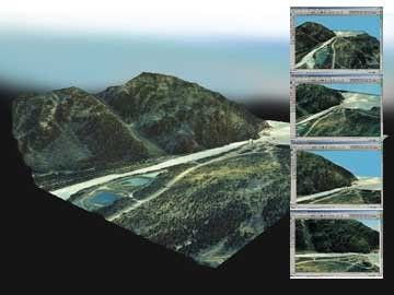
TIN as wireframe, coloured and with
orthophotos draped over it....
TIN generation .....

    • Customer running 10gR2 …
         – Cannot use 11gR1 TIN functionality to create
           TIN from points.
         – Used Feature Manipulation Engine (FME) to
           create a TIN from contours generated from
           LiDAR data.
              • Could have used LiDAR but didn't have access.
              • TIN converted into 3D vector triangles (facets) and
                loaded into Oracle as 3D polygons and Rtree indexed.
 SQL> SELECT geom FROM sp_triangles WHERE rownum < 3;

 GEOM(SDO_GTYPE, SDO_SRID, SDO_POINT(X, Y, Z), SDO_ELEM_INFO, SDO_ORDINATES)
 ---------------------------------------------------------------------------
 SDO_GEOMETRY(3003, 82469, NULL, SDO_ELEM_INFO_ARRAY(1, 3, 1),
 SDO_ORDINATE_ARRAY(454007.806, 6420093.62, 4.5, 454035.602, 6420003.74, 5,
 454029.773, 6420004.82, 5, 454007.806, 6420093.62, 4.5))
 SDO_GEOMETRY(3003, 82469, NULL, SDO_ELEM_INFO_ARRAY(1, 3, 1),
 SDO_ORDINATE_ARRAY(454007.806, 6420093.62, 4.5, 453999.997, 6420099.25, 4.5,
 454006.511, 6420094.75, 4.5, 454007.806, 6420093.62, 4.5))
Modelling zone of influence solid...
• In the 2D case, the Zone of Influence is
generated by simple buffer generation at
ends of each vector (only location where
depth from surface exists) with a convex hull
joining the two buffers to make a elongated
area that “smooths” the differences between
the trench widths at each end.
– Cannot do this with 3D as ground surface
varies all along the pipe.
Input
Ground Surface Depth
ewer Pipe
Output Water/S
DepthSampling...
• In order to create an accurate polygon
representing the intersection of the ZOI and
the natural surface, we need to construct an
algorithm that “samples” the ground surface
at points along the pipe.
– The sampling chosen is to “densify” the pipe
graphic at a number of points represented by
a maximum distance.
• If sample distance is 3 meters and
• Pipe length is 7 meters, we end up sampling at
• 2 /* End points */ + ( 7 / 3 ) /* Intermediate points */
= 4 points
2.3m 2.3m 2.3mRay generation....
• At each sample point along the pipe we
construct an 3D vector that represents the
bottom of the ZOI.
– Must be sufficiently projected into space to
guarantee intersection with ground surface
represented by TIN facet.
Sloping ground
Vector / TIN facet
intersection = surfaceEnd of Pipe
• At each end of the pipe, ZOI rays are created
around a semi-circular arc as follows:Ray Facet Intersection...
• Once we have constructed the 3D ray
representing the bottom of the ZOI we need
to be able to find the first TIN facet/triangle it
intersects and the exact point, in X, Y and Z
• Found algorithm:
“Determining whether a line segment intersects a
3 vertex facet”, Research Associate Professor Paul
Bourke, University of Western Australia,
February 1997
– http://local.wasp.uwa.edu.au/~pbourke/geometry/linefacetPutting it all together....
• PL/SQL function to encapsulate 3D
processing was constructed:
• The function:
– Creates sample points along pipe;
– Generates ray representing bottom of ZOI to
left/right of pipe;
• At each end of pipe sample rays were created around a
semi-circular arc.
– Searches for surface point;
– Constructs 3D polygon from found surface points.Facet searching...
• The searching for the TIN Facets to find the
surface point was done as follows:Calling SQL ....
• The original 2D ZOI SQL underwent a
relatively small modification to ensure it
called the ThreedArea() function correctly....
– Means existing Trigger based framework can
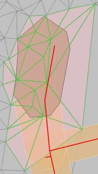
be reused with little change.Comparison...
• The image below shows the difference in
output between the two methods.Building Check (planimetric).
42% more
buildings
affected
by
3D ZOI
then
2D ZOIComparative Performance
• Rebuild time:
– 2D is less than 10 minutes for 22,299 polygons
(ie 37/sec) 193 polygons in 6 seconds = 32/sec
– 278 seconds for 184 polygons = 0.66/sec
• 3D “Sampling” approach sees far greater
searching and processing than 2D
– Bulk facet searching (see FindEndPoint()
function) should improve performance
• 11gRx Clip_Tin may help here.To Be Done...
• Improve performance:
– PL/SQL code profiling;
– Bulk line(ray)/facet processing.
• Easement processing.
• Handle soils polygon changes inside pipe.
• Possible upgrade to 11g TIN.
• Possible use of 11gR1 compound triggers.11g....
11gR1 and 11gR2 TIN

• So we can model the ZOI volume as a solid
  and not just a 3D polygon output from the
  ThreeDArea PL/SQL function.
11gR1 and 11gR2 and TINs

  • 11gR1 introduces a TIN structure and the
    methods:
     – SDO_TIN, SDO_TIN_BLK_TYPE and
       SDO_TIN_BLK data types;
     – Package called SDO_TIN_PKG implements
       TIN processing.
Comparison...
• The new TIN functionality in 11g
is limited to:
– Creating a TIN from a set of
points (eg LiDAR data);
– Clipping the TIN to return
triangles that are within a
specified query window;
– Returning those clipped triangles
as sdo_geometry objects.
• However... TIN clipping doesn't
clip, it just selects whole facets
(green) as in the image on the left
(selection area is outlined in
gray).Comparison...
• So, 11gR1/2 TIN functionality cannot generate the
area of intersection between a solid, surface or a
TIN.
– In the ZOI application, use of 11g Tin would:
• Remove need for FME TIN creation (2% of current task);
• Enable use of SDO_TIN_PKG.CLIP_TIN and
TO_GEOMETRY functions but this would change
only the SQL in ThreedArea()'s Find_End_Point()
function (5% of current task)
– Still need to:
• Process the pipes as is currently done;
• Create LineFacet function (surface point computation);
• Collect surface points together to create 3D polygon.
• These are 90% of current task!Value of 11gRx TIN?
• Would we port to Oracle's TIN structures and
processing when we upgrade to 11gRx?
– Customer has accurate LiDAR elevation data across
whole area of operations.
• Unlikely to see it redone in the next 10 years.
• Therefore, TIN generation is a fairly static process.
• Customer already has FME (doesn't support Oracle TINs
as yet) so don't need 11gRx TIN generation functionality.
– Current “TIN-as-3D-triangles” approach is capable of
being viewed and processed in standard GIS packages
in use at customer site (none currently support Oracle's
TIN structures).
• Approach is capable of cross-database implementation!
– Use 11g TIN only if can improve processing speed or new
Solid/TIN intersection functionality is added in later release.Conclusion
• Implementation Goals Achieved:
Minimise PL/SQL programming:
Use of a single function to generate ZOI area;
Single SQL statement approach;
GetVector(), TO_3D() etc was reuse of existing PL/SQL code.
Rest of PL/SQL package was about “framework” and not
programming a solution/algorithm.
Maximal re-use of previous 2D approach.
e.g. SQL and efficient trigger based recalculation system.
Extract as much value from Oracle and Oracle Spatial as
possible;
Pure SQL approach to solution with clever use of TABLE
function.
Use of LRS functions in non-LRS application;
SDO_AGGR_CONCAT_LINES() used.
SDO_NN for finding nearest soils polygon;
SDO_ANYINTERACT for line/facet searching.Questions • Any questions?
You can also read