Real-Time Incremental Estimation of Retinal Surface Using Laser Aiming Beam
←
→
Page content transcription
If your browser does not render page correctly, please read the page content below
Real-Time Incremental Estimation of Retinal
               Surface Using Laser Aiming Beam
      Arpita Routray, Robert A. MacLachlan                          Joseph N. Martel                         Cameron N. Riviere
                The Robotics Institute                       Department of Ophthalmology                   The Robotics Institute
              Carnegie Mellon University                       University of Pittsburgh                  Carnegie Mellon University

   Abstract—Vitreoretinal surgery procedures demand high pre-
cision and have to be performed with limited visualization and
access. Using virtual fixtures in conjunction with robotic surgery
has the potential to improve the safety and accuracy of these
procedures. A cornerstone of many of these virtual fixtures is
reconstruction of the retinal surface with respect to the surgical
tool, which is difficult to obtain due to the inadequacy of
traditional stereo vision techniques in the intact eye. A structured-
light technique applied using an actuated handheld instrument
has been proposed to combat this problem, but it only provides
a reconstruction at the start of the procedure; it cannot update
it as the eye moves during surgery. We propose updating the
initial estimate of the retinal plane a single point at a time, by
continued detection of a laser aiming beam in each camera frame,
as in the initial structured-light approach. This paper presents
the technique and demonstrates it via experiment.

                       I. I NTRODUCTION
   Vitreoretinal surgery procedures involve manipulating small,
delicate structures within the eye and demand high precision.
For example, during membrane peeling, the 5-10 µm-thick
internal limiting membrane (ILM) has to be removed around
macular holes and requires repeated attempts by surgeons over
several minutes [1]. Another procedure, retinal vein cannula-
tion, involves drug delivery to retinal vessels less than 100
microns in diameter [2]. In addition to precision requirements,         Fig. 1. Micron system setup, showing Micron handheld vitreoretinal surgical
these procedures have to be performed with limited visualiza-           instrument, ASAP optical tracker, stereo operating microscope, and cameras.
tion and constrained access, and hence are quite challenging
for surgeons. Many robotic platforms have been developed
                                                                        methods of registering the position of the retina to the surgical
specifically to address these challenges. These include the
                                                                        tool tip. In [7], the authors use the distance between the tool
Preceyes Surgical System [3], the JHU Steady Hand Robot
                                                                        tip and its shadow in the acquired images to detect proximity,
[4], and Micron, an active handheld micromanipulator [5].
                                                                        but the method does not provide the exact distance of the
   Virtual fixtures during robotic vitreoretinal surgery can
                                                                        tool tip from the retina. A focus-based 3D localization method
improve both the safety and accuracy of these procedures [6].
                                                                        using the Navarro schematic eye is developed in [8], but the
However, an accurate estimate of the position of the retina
                                                                        localization error is limited to a few hundred microns.
with respect to the tool tip is a requirement for the success
of many of these visual fixtures. Retinal surface estimation               In all of the above methods, the tool tip is localized using
is difficult because traditional stereo surface reconstruction          visual feedback. On the other hand, the tool tip of the handheld
methods cannot be used successfully. This is because, during            robot Micron can be tracked at all times using a custom built
surgery, the optical path involves the cornea, the lens, saline,        optical tracking system called Apparatus to Sense Accuracy of
and also a BIOM (Binocular Indirect OphthalmoMicroscope)                Position (ASAP) [9]. Taking advantage of this information, a
lens.                                                                   new method for retinal surface reconstruction was introduced
   Due to the shortcomings of traditional reconstruction meth-          in [10] using structured light applied by a laser aiming beam.
ods in the intact eye, many authors have proposed alternative           This method involves moving the Micron tool tip in a circular
                                                                        trajectory, which is practical only before beginning a surgical
                                                                        procedure, and not during it. Thus, it can only provide an
978-1-5386-7825-1/19/$31.00 ©2019 IEEE                                  initial estimate of the retinal plane and is not suitable for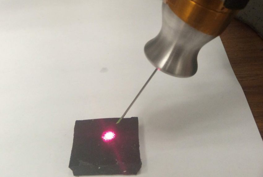
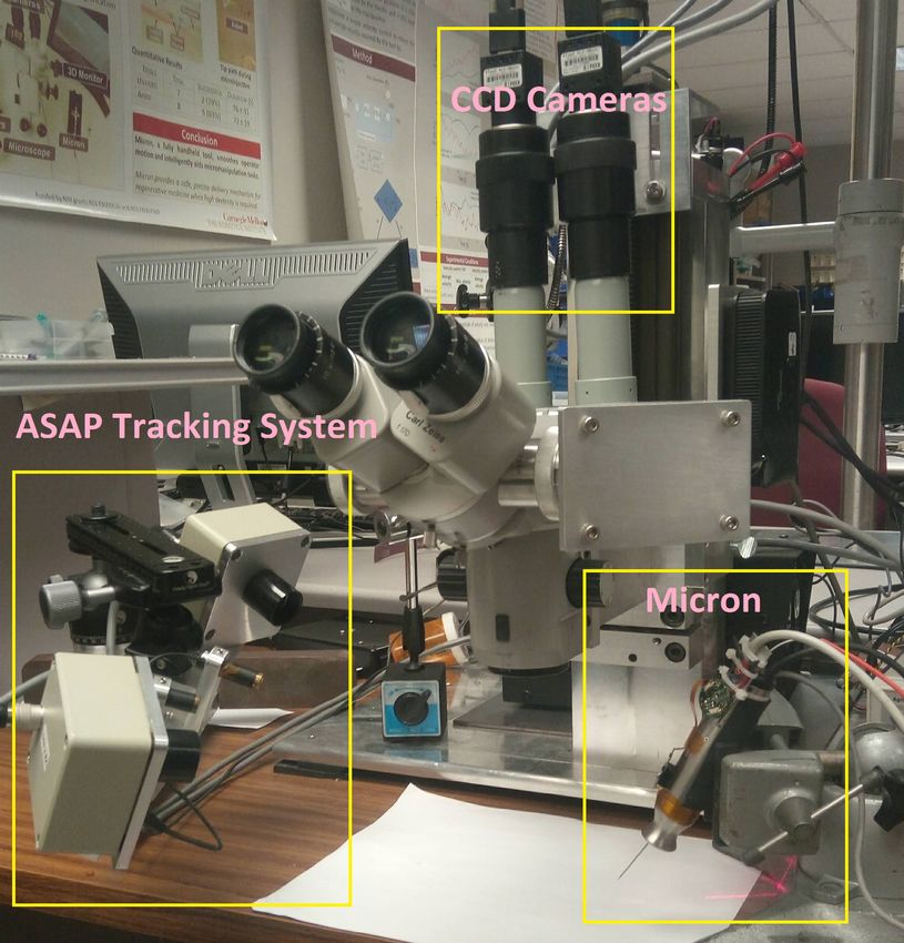
with Micron, and the end-effector can effectively be used as
a laser pointer as shown in Figure 2. The method involves
scanning of the micron end-effector in a circular trajectory,
resulting in an elliptical laser trajectory on the retinal surface.
Geometric analysis of the resulting elliptical pattern gives
an estimate of the retinal surface in ASAP coordinates. The
method was tested in various conditions and its feasibility was
established in a realistic eye model which incorporated optical
distortion by lenses.
The human eyeball is a part of a sphere with a diameter
of approximately 25 mm. However, the portion of the retina
directly visible under the microscope only consists of an area
around 4mm wide, which is a small part of this sphere and
has relatively lower curvature. Thus, the retinal surface under
the microscope can be approximated by a plane and the depth
Fig. 2. Laser interfaced with the Micron end-effector. error resulting from this planar assumption is less than 100
µm.
At any point of time t, we first estimate the point at which
intraoperative updates. the laser beam interfaced with micron intersects the retinal
During vitreoretinal surgery the patient is sedated rather surface in 3D ASAP coordinates. Given the noisy triangulated
than anesthetized, and movements of the eye are common. beam points, we then outline a method to update the estimate
To account for movement of the retinal surface, we propose of a point on the plane and the plane normal. Πt is used to
a method that updates the estimate of the retinal plane in denote the estimated plane at the instant t. For this study, the
real time. At every iteration, the update method computes the initial estimate of the plane at time t = 0, Π0 , is assumed as
position of a single point of the laser aiming beam on the given.
retinal surface in the coordinates of the optical tracking system
[9]). However, due to inaccuracies in camera calibration and A. Estimation of a Single Point on Retinal Plane
location of beam center in each frame, these points are noisy. As we are demonstrating the feasibility of our method in
Our method uses these noisy points to update the value of open-sky conditions, we use stereo vision to triangulate the
the previous plane estimates. This paper presents the method, position of a single point on the retinal plane. To do so,
and demonstrates the general feasibility wherein a lof updating we first calibrate each camera’s 2D image coordinate system
the retinal plane using a single point per camera frame in an to the 3D ASAP coordinate system. To get correspondences
”open-sky” experiment. between the camera coordinates and ASAP coordinates, the
Micron tool tip is detected in each camera and its 3D position
II. M ETHODS
Micron is an active handheld robotic instrument for accu-
racy enhancement that can provide active compensation for
the surgeons physiological hand tremor [5] as well as a variety
of virtual fixtures [10]. The version of Micron used for this
experiment is a six-degree-of-freedom (6DOF) system with the
end-effector attached to a prismatic-spherical-spherical Gough
Stewart platform that uses piezoelectric linear motors [5].
The end-effector has a cylindrical workspace that is 4mm in
diameter and 6mm long with its null position at the centroid
of the space. The device has a set of 3 LEDs fixed to the
handle, which are optically tracked by ASAP at a sampling
rate of 1 kHz. The full 6DOF pose of the handle is computed
by triangulating three frequency-multiplexed LEDs mounted
on the instrument [9].
The vision system comprises 2 CCD cameras mounted on
an operating microscope as shown in Figure 1. All experiments
are conducted under the microscope and in full view of the
two cameras. The cameras are connected to a desktop PC,
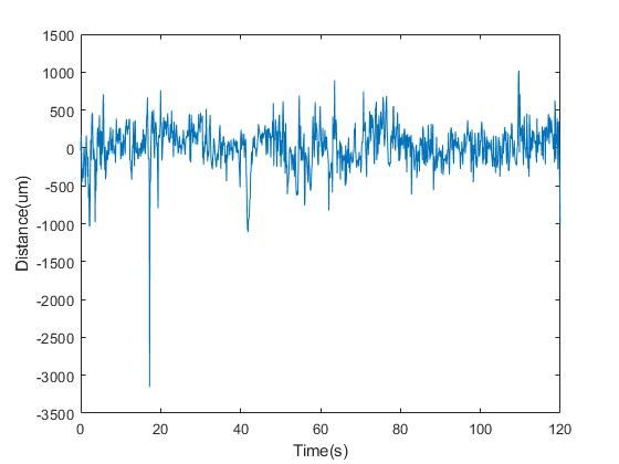
Fig. 3. Distances of the estimated position of the intersection of the laser
which handles image processing. beam and the retinal surface from the true retinal plane during the surface
In order to use the structured-light technique for retinal sur- tracking experiment. The plot demonstrates that the triangulated beam points
face estimation described in [10], a surgical laser is interfaced are noisy, and hence should be filtered.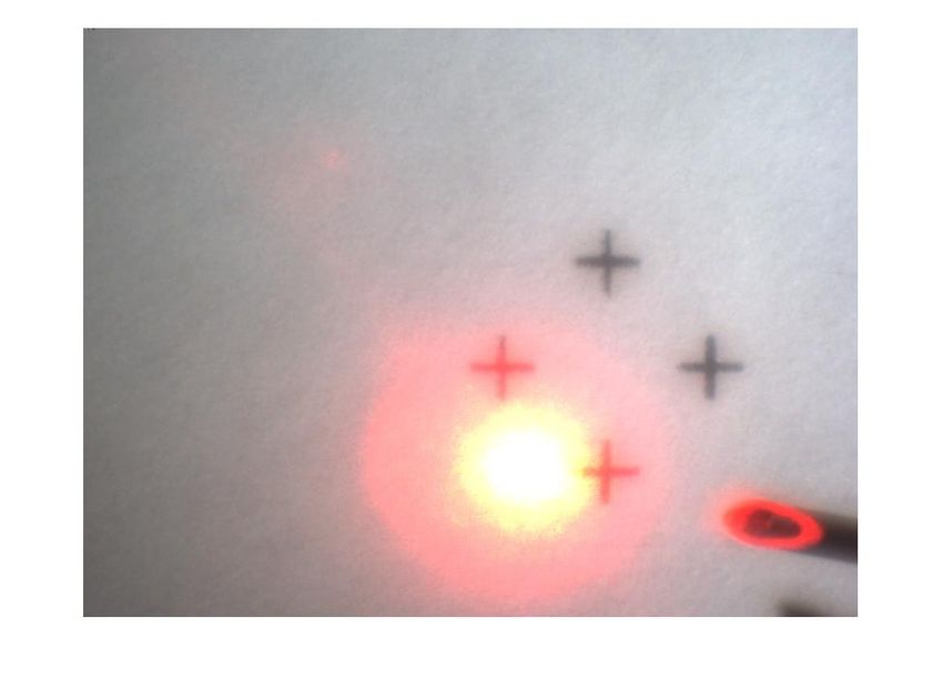
in ASAP coordinates is recorded simultaneously. Using these
correspondences, the projection matrices of both cameras are
computed using DLT and RANSAC [6].
   In order to optimize the speed of our algorithm, an initial
approximation of the center of the laser beam in the left and
right camera images, pl0 , and pr0 is computed using simple
thresholding operations. However, as the beam appears diffuse
under the microscope, this position may not be the exact
point at which the laser beam intersects the retinal surface.
We assume that the actual position of the laser beam differs
from the initial approximation in the left and right images by
constant offsets, ρl and ρr , respectively. Thus, if pl and pr
be the actual positions at which the laser beam intersects the
retinal surface, we have
                             pl = pl0 + ρl
                                                                 (1)
                           pr = pr0 + ρr
                                                                       Fig. 4. Fiducials used for estimation of the true plane during the surface
   For a set of planes Πi and the corresponding beam                   tracking experiment.
locations pl,i and pr,i , we define the following terms:
T (pl,i , pr,i ), the triangulated 3D point using pl,i , pr,i          a weighted sum of the previous estimate and n0t . If nt be the
di , Signed distance between T (pl,i , pr,i ) and the plane Πi         estimate of a point on the plane at time t, then
M (di ), Median over all di                                                                nt = wn n0t + (1 − wn )nt−1                       (4)
µx (|di |), x% Trimmed mean over all |di |
                                                                       where the parameter wn is the weight corresponding to the
                                                                       latest normal update.
   The offsets ρl andρr are then computed by minimization of
the following objective function:                                      D. Noisy and Missing Points
                                                q
   F (ρl , ρr ) = 0.5 M (di ) + 0.5 µ5 (|di |) + ρ2l + ρ2r (2)            If the distance between T (pl,t , pr,t ) and the estimated plane
                                                                       Πt−1 is greater than a threshold ∆d , or if the laser beam is
   Minimization of the first term ensures that the triangulated        not detected in the camera images, we set pl,t = pl,t−1 and
beam points are distributed evenly above and below the true            pr,t = pr,t−1 . Pt and nt are then computed as usual using (3)
retinal plane, thus avoiding any offsets during plane estima-          and (4). This ensures that the estimated plane is not stagnant
tion. Minimization of the second term reduces the distances of         during such instances and keeps moving incrementally towards
the triangulated beam points from the true retinal plane. The          the last position of the triangulated beam point. Hence, once
third term is simply used for regularization.                          we again get a usable value of T (pl,t , pr,t ); the plane update
B. Surface Point Update                                                resumes with a reduced lag.
   The triangulated beam points computed in II-A are noisy. In         E. Experimentation
order to filter out high-frequency noise components, we use a             A separate dataset spanning 100 seconds is used to compute
moving average filter, and the estimate of a point on the plane        ρl andρr by optimizing (2). Using this method, we get ρl =
is computed as a weighted sum of the previous estimate and             [1.12, 1.70] pixels and ρr = [-2.99, 0.69] pixels. For update of
the latest filtered beam point. If Pt be the estimate of a point       the plane normals, we use the past mn = 7 points, an update
on the plane at time t, then                                           weight of wn = 0.015, and a minimum distance between fitted
                     t
                     X                                                 points, ∆n = 50µm. For update of the points on the plane,
           Pt = wp        T (pl,i , pr,i ) + (1 − wp )Pt−1       (3)   we use a filter window size of kp = 4 and an update weight
                    i=t−kp                                             of wp = 0.2. The threshold for classifying a point as noise,
where the parameters kp and wp are the filter window size              ∆d is 5mm. All parameters remain constant throughout the
and the weight corresponding to the latest point update,               experiment; their values were selected via trial and error.
respectively.                                                             An initial estimate of the retinal plane is provided at
                                                                       t = 0, following which we track changes in this plane over
C. Surface Normal Update                                               a period of 120 seconds. Over this time period, the plane
  An intermediate value of the plane normal, n0t , is computed         is rotated and translated manually. Hence, the plane motion
by fitting a plane to the last mn triangulated beam points,            is noisy. As shown in Figure 4, four cross-shaped fiducial
such that all points are at least a distance ∆n away from from         markers are placed on the surface to be estimated. Ground
each other. The estimate of the plane normal is computed as            truth is computed by detecting the centers of the fiducials,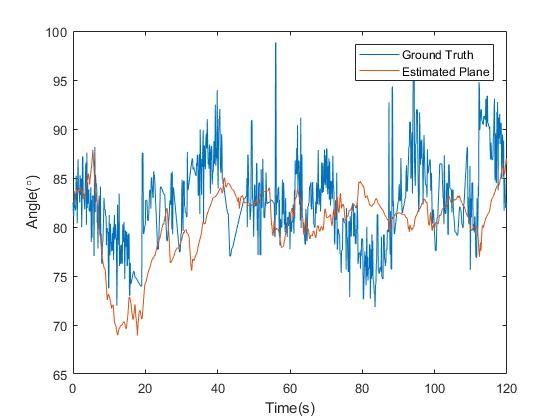
triangulating to obtain their positions in 3D coordinates, and
then fitting a plane to these points. This method to obtain
ground truth yields reliable estimates of the true retinal plane
during the experiment. In frames where the fiducial markers
are not visible from the camera due to sudden movements, the
ground truth plane is computed by interpolation.
III. R ESULTS
Although the optimized offsets ρl = [1.12, 1.70] pixels and
ρr = [-2.99, 0.69] pixels are quite small, the median signed
distance M (di ) and the trimmed mean distance µ5 (|di |), as
defined in II-A, reduce by 95.75% and 64.36% in the test
dataset.
During the tracking period, we measure the displacement of
the updated plane along the ASAP coordinate system’s z axis
with respect to a stationary point on the initial plane, and find
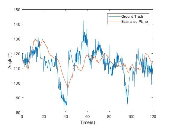
that movement along this axis is compensated by 44.43%. As (a) Angle between plane normal and x axis
the plane normal is almost perpendicular to the ASAP system’s
x and y axes, we do not measure displacement along these
other directions. Translations of the estimated plane and the
true plane along the z axis over the tracking period is shown
in Figure 6. We also measure the angles of the estimated and
true plane normals with respect to the ASAP system’s x, y,
and z axes during this period. These values are plotted over
time in Figure 5 and we observe that for the most part, the
estimated normal follows the trends of the true plane normal.
IV. D ISCUSSION
In this paper, we proposed an algorithm for updating the
retinal plane using noisy aiming beam samples, where only
one new point is obtained from each incoming camera frame.
We demonstrated the general feasibility of the method by
tracking a plane in an open-sky experiment using printed
fiducial markers as ground truth. We found that our method is
able to track changes in the retinal plane in a stable manner, (b) Angle between plane normal and y axis
even when the plane is displaced by several millimeters.
Motion of the retinal plane perpendicular to the plane
normal does not change its geometrical position in space with
respect to the surgical tool tip, and hence cannot be tracked
by this algorithm. However, Braun et al. have presented
techniques for vision-based intraoperative tracking of retinal
vasculature, which can perform this function [11]. Future
work will involve combining these algorithms to tracking
movements of the retinal surface in six degrees of freedom.
For the surface-tracking experiment conducted in this paper,
the parameters used were constant and were selected via trial
and error. Although this demonstrated the general feasibility of
our method, future work will involve more systematic tuning
of these parameters in order to improve the accuracy of the
plane update and the lag that is visible in Fig. 5. Since this
experiment was conducted open-sky, we were able to use
stereo vision to determine the intersection of the laser beam (c) Angle between plane normal and z axis
and the retinal surface. Going forward, we plan to investigate
finding this point of intersection in an intact eye, which will Fig. 5. Angles of the estimated and true plane normals from the x,y, and z
require alternative means of obtaining ground truth. axes during the surface tracking experiment.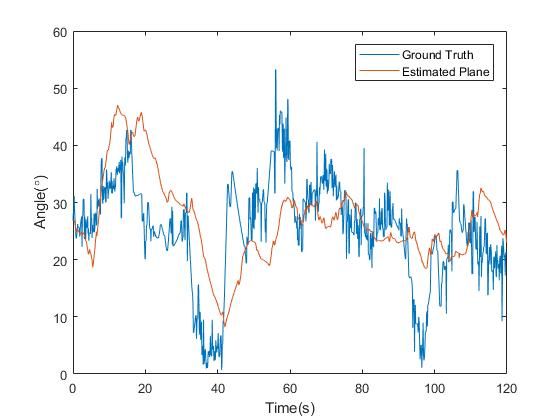
[8] C. Bergeles, K. Shamaei, J. J. Abbott, and B. J. Nelson, “Single-camera
                                                                                     focus-based localization of intraocular devices,” IEEE Trans. Biomed.
                                                                                     Eng., vol. 57, no. 8, pp. 2064–2074, 2010.
                                                                                 [9] R. A. MacLachlan and C. N. Riviere, “High-speed microscale optical
                                                                                     tracking using digital frequency-domain multiplexing,” IEEE Trans.
                                                                                     Instrum. Meas., vol. 58, no. 6, pp. 1991–2001, 2009.
                                                                                [10] S. Yang, J. N. Martel, L. A. Lobes Jr, and C. N. Riviere, “Techniques for
                                                                                     robot-aided intraocular surgery using monocular vision,” Int. J. Robotics
                                                                                     Research, vol. 37, no. 8, pp. 931–952, 2018.
                                                                                [11] D. Braun, S. Yang, J. N. Martel, C. N. Riviere, and B. C. Becker,
                                                                                     “EyeSLAM: Real-time simultaneous localization and mapping of retinal
                                                                                     vessels during intraocular microsurgery,” International Journal of Med-
                                                                                     ical Robotics and Computer Assisted Surgery, vol. 14, no. 1, p. e1848,
                                                                                     2018.

Fig. 6. Plane displacement along z axis over the surface tracking period. The
displacement in the z axis is computed with respect to a stationary point on
the initial plane.

   Application of this technique presupposes the presence of a
laser aiming beam in the instrument, which is presently true
only of therapeutic laser instruments. However, in principle
it is possible to incorporate a laser aiming beam within the
intraocular shaft of any type of instrument for any type of
intervention. Our group is presently working to incorporate
aiming beams into instruments for non-laser retinal operations.

                         ACKNOWLEDGMENT
   Funding provided by U.S. National Institutes of Health
(grant no. R01EB000526).

                             R EFERENCES
 [1] A. Almony, E. Nudleman, G. K. Shah, K. J. Blinder, D. B. Eliott, R. A.
     Mittra, and A. Tewari, “Techniques, rationale, and outcomes of internal
     limiting membrane peeling,” Retina, vol. 32, no. 5, pp. 877–891, 2012.
 [2] K. Kadonosono, S. Yamane, A. Arakawa, M. Inoue, T. Yamakawa,
     E. Uchio, Y. Yanagi, and S. Amano, “Endovascular cannulation with a
     microneedle for central retinal vein occlusion,” JAMA Ophthalmology,
     vol. 131, no. 6, pp. 783–786, 2013.
 [3] T. L. Edwards, K. Xue, H. C. M. Meenink, M. J. Beelen, G. J. L. Naus,
     M. P. Simunovic, M. Latasiewicz, A. D. Farmery, M. D. de Smet, and
     R. E. MacLaren, “First-in-human study of the safety and viability of
     intraocular robotic surgery,” Nature Biomedical Engineering, vol. 2018,
     pp. 649–656, 2018.
 [4] A. Üneri, M. A. Balicki, J. Handa, P. Gehlbach, R. H. Taylor, and
     I. Iordachita, “New steady-hand eye robot with micro-force sensing for
     vitreoretinal surgery,” in Proc. IEEE Int. Conf. Biomedical Robotics and
     Biomechatronics, 2010, pp. 814–819.
 [5] S. Yang, R. A. MacLachlan, and C. N. Riviere, “Manipulator design
     and operation of a six-degree-of-freedom handheld tremor-canceling
     microsurgical instrument,” IEEE/ASME Trans. Mechatron., vol. 20,
     no. 2, pp. 761–772, 2015.
 [6] B. C. Becker, R. A. MacLachlan, L. A. Lobes Jr., G. D. Hager, and C. N.
     Riviere, “Vision-based control of a handheld surgical micromanipulator
     with virtual fixtures,” IEEE Trans. Robot., vol. 29, no. 3, pp. 674–683,
     2013.
 [7] T. Tayama, Y. Kurose, T. Nitta, K. Harada, Y. Someya, S. Omata, F. Arai,
     F. Araki, K. Totsuka, T. Ueta et al., “Image processing for autonomous
     positioning of eye surgery robot in micro-cannulation,” Procedia CIRP,
     vol. 65, pp. 105–109, 2017.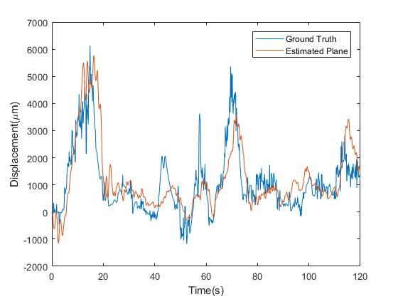
You can also read