Towards a Multispectral RGB-IR-UV-D Vision System - Seeing the Invisible in 3D
←
→
Page content transcription
If your browser does not render page correctly, please read the page content below
Towards a Multispectral RGB-IR-UV-D Vision System — Seeing
                                                              the Invisible in 3D

                                                                 Tanhao Zhang, Luyin Hu, Lu Li, and David Navarro-Alarcon

                                            Abstract— In this paper, we present the development            "hidden features". In this article, we are using a depth
arXiv:2108.08494v1 [cs.RO] 19 Aug 2021

                                         of a sensing system with the capability to compute                camera, a UV camera and a thermal (LWIR) camera
                                         multispectral point clouds in real-time. The                      to build 3D multispectral vision system and make a
                                         proposed multi-eye sensor system effectively registers            special tool to calibrate all these cameras.
                                         information from the visible, (long-wave) infrared,
                                                                                                              Thermal camera is a useful tool to conduct
                                         and ultraviolet spectrum to its depth sensing frame,
                                         thus enabling to measure a wider range of surface
                                                                                                           measurement and analysis tasks. It measures the
                                         features that are otherwise hidden to the naked                   thermal information without contact and shows
                                         eye. For that, we designed a new cross-calibration                temperature in imaging way [2]. 3D camera can
                                         apparatus that produces consistent features which can             get both visible spectrum (red, green, blue) and
                                         be sensed by each of the cameras, therefore, acting as            depth information, which has been widely used in
                                         a multispectral “chessboard”. The performance of the              the robotics community [3]. UV camera is used for
                                         sensor is evaluated with two different cases of studies,          quality inspection, body fluid trace detection, sulfur
                                         where we show that the proposed system can detect                 dioxide (SO2 ) detection [5] and so on. In [9], Springer
                                         “hidden” features of a 3D environment.
                                                                                                           et al. proved that UV can be absorbed by body fluid
                                                          I. INTRODUCTION                                  because of amino acids in these secretions. In [6],
                                                                                                           UV image is used for checking the skin issues of
                                            The use of consumable three-dimensional (3D)                   humans face because the pigment of skin absorbs
                                         vision systems has significantly exploded in the                  more UV that show higher contrast image than visible
                                         past decade (particularly, with the ubiquitous RBG-               spectrum image, thus easier and faster to detect some
                                         D sensors). The availability of these affordable                  skin issues.
                                         3D cameras has triggered many developments                           In the past two decades, there have been many
                                         in important areas such as artificial intelligence,               articles put forward their own way to build 3D models
                                         autonomous systems, service robotics, autonomous                  with thermal information in different ways. In [7],
                                         driving [1], to name a few cases. However, most                   Vidas et al. fused thermal camera with a structure
                                         existing depth sensors are only equipped with a                   light 3D camera (Kinect v1) and proposed a new
                                         visible spectrum camera, along which they form                    technique for calibration, which did not need artificial
                                         3D models of the environment. In some special                     targets (checkerboard). However, they assumed that
                                         occasions, such as criminal investigation and energy              both two cameras had similar fields of view, which is
                                         auditing [4] , visible spectrum is not enough. A                  really hard to achieve when we use low-cost thermal
                                         3D multispectral vision system that can perceive the              camera which is inapplicable for the wildly used low-
                                         electromagnetic wave period from ultraviolet (UV) to              cost thermal cameras since their field of views are
                                         long-wave infrared (LWIR) is needed to detect some                relatively smaller than regular RGB cameras. In [8],
                                           This work is supported in part by the Research Grants Council
                                                                                                           Shivakumar et al. reflectivity based calibration is used
                                         of Hong Kong under grant 15212721, in part by the Jiangsu         for getting the intrinsic and extrinsic parameters of
                                         Industrial Technology Research Institute Collaborative Research   the thermal and RGB-D camera. They use different
                                         Program Scheme under grant ZG9V, and in part by the Chinese       materials that have different emissivities (ε ) of LWIR
                                         National Engineering Research Centre for Steel Construction
                                         Hong Kong Branch under grant BBV8.                                to make "black" and "white" parts of checkerboard
                                           Tanhao Zhang, Luyin Hu and David Navarro-Alarcon are            that yield high contrast images in both the thermal
                                         with The Hong Kong Polytechnic University, Department of          camera and RGB camera. The calibration principle
                                         Mechanical Engineering, Hung Hom, Kowloon, Hong Kong.
                                                                                                           and processing is the same as RGB camera. However,
                                         (Corresponding author’s e-mail: dna@ieee.org)
                                           Li Lu is with the Changzhou Institute of Advanced Technology,   this method needs a large and stable heat source to
                                         Changzhou, Jiangsu Province, China.                               generate the "reflex", which is not convenient for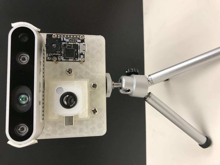
Heater strip RGB-D camera
II. METHODS
A. A New Multispectral Calibration Tool
Traditional calibration boards that use Zhang’s
calibration method [11] are checkerboards that use
Black box power source
black and white blocks to make a high contrast in the
image to detect feature points. However, for cameras
UV camera which detect invisible light, i.e., UV (ultraviolet)
RGB image Thermal image UV image
Thermal camera
cameras and LWIR (long wave infrared) cameras, are
(a) (b) not suitable for this traditional calibration tool. We
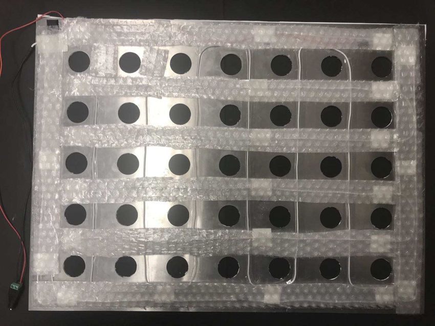
Fig. 1: The calibration tool and result of calibration: (a): find that black blocks of the original calibration board
Top left - facade of calibration tool. Top right - revise side can reflect a lot of UV although they can absorb most
of calibration tool. (b): 3D Multispectral Vision System of visible light, thus feature points cannot be detected
clearly by UV camera. And LWIR camera is sensitive
to temperature. So, a newly designed calibration tool
to calibration both visible light and invisible light is
designed to calibration cameras which are sensitive
setting the calibration environment. There are few to different spectrum.
articles related to building a 3D model with UV. The main part of the calibration tool is a
Based on our current knowledge, this is the first time rectangular aluminum plate with even-distributed
that a complete multi spectral RGB-IR-UV-D vision circle holes on it and covered with white paper
system is developed. on the front. Heater strip is placed at the back of
the plate. Heater strip will heat aluminum plate to
With the on-going COVID-19 pandemic, people make sufficient contrast for LWIR camera (thermal
are paying increasing attention to environmental camera). To make sure that all cameras can be
hygiene and personal hygiene [10]. Our idea came calibrated together, we make a black box that light
out when we think if there is a way to build a 3D can get in the box from holes on the aluminum board,
modeling system that can measure the temperature but the main part of light is absorbed by reflecting
and find some place which is contaminated and many times in the black box, little get out from holes.
needed to be clean. This system needs to be Visible light and UV light are reflected by white
lightweight and can be attached to a mobile robot. paper (covered on the aluminum board) and absorbed
The temperature and 3D information can be collected by holes. As the Fig.1 shows, sufficient contrast can
by a thermal camera and a depth camera. To detect be detected by RGB camera, LWIR camera and UV
the contamination, we decided to use UV camera camera. Once the features of the calibration tool
because most of biohazardous pollutant contains (black circles) were detected, we mark the center of
amino acids and can be visualized by UV camera, circle and use OpenCV’s camera calibration function
and all information is in image format which means to get intrinsics of every camera and transformations
easier to be processed. To calibrate these cameras, matrices of each camera coordinates.
we need to build a special calibration tool that can
calibrate multi-spectrum and is flexible to use. B. Alignment of 3D Multispectral Images
The original contribution of this work is twofold: 3D multispectral visible system has three different
(i) A new calibration tool is proposed to effectively kinds of camera, RGB-D camera, thermal camera and
cross-calibrate multispectral images; (ii) A 3D vision ultraviolet camera. Each camera can be simplified
system is developed to automatically detect and as a distorted pinhole camera model. The RGB-D
register features in the LWIR and UV spectrum. camera is RealSense D435 depth camera which RGB
and depth image have been aligned, thermal camera
The rest of this article is organized as follows: is a FLIR lepton 3.5, whereas the UV camera is a
Sec. II presents the design of the multispectral camera with ultraviolet sensitive CMOS and special
vision system; Sec III experimentally validates the lens which only pass ultraviolet which wavelength
performance of the system; Sec. IV gives final from 235nm to 395nm. Camera specifications are
conclusions. summarize in Table I.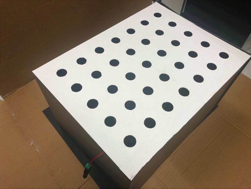
w(X, Y, Z)
uv
Iuv , Crgb thermal
of undistorted RGB and UV images and their pixel
Ithermal , Crgb
coordinates pu,rgb and pu,uv .
(Irgb)−1
To map each point of pu,uv to pu,rgb , we first make
each pixel include their own depth by using the depth
Di,depth image Ddepth acquired from the RealSense D435 to
pi,uv pi,th form a 3D array which can present the position of
each pixel in the 3D world. And then projecting each
UV image pi,rgb Depth image Thermal image
point in 3D world of RGB camera to UV camera
by using the relative camera coordinate Crgbuv , i.e the
RGB image
(a)
transformation matrix of RGB camera coordinate and
UV camera coordinate. We use the homogeneous
UV camera uv
[Rworld uv
, Tworld ]
coordinate representation to denote 2D points and
yc,uv
by pu =[u, v, 1]T . For one point i, We can obtain a
zc,uv
Duv
point position in 3D world coordinate wi by using
IR camera xc,uv the equation below:
yc,IR yw
zc,IR xw
wi = Irgb −1 × pu,rgb · Di,depth (1)
Drgb
zw
xc,IR RGB-D camera Then we use the homogeneous coordinate represent
yc,rgb
3D point wi =[X ,Y, Z, 1]T and project wi to the UV
zc , rgb uv to get
image using the relative camera coordinate Crgb
xc,rgb
rgb
[Rworld rgb
, Tworld ] pi,u,uv :
uv
(b)
pi,u,uv = Iuv ×Crgb × wi (2)
Fig. 2: Alignment procedure of multispectral device: (a) - Where vector pi,u,uv presents as homogeneous
Knowing intrinsics of each cameras, relative extrinsics and uv include rotation and translation
coordinate form. Crgb
depth (distance), a point in RGB image can be projected matrix of RGB camera and UV camera,Ruv uv
rgb and Trgb ,
to 3D world and then project to UV image and thermal
which present coordinate transformation of cameras.
image. (b) - Getting the relative extrinsic of two cameras.
uv uv
uv Rrgb Trgb
Crgb = (3)
TABLE I: specifications of camera 0 1
uv , assuming C , C
To obtain Crgb
Sensor Thermal camera RGB-D camera UV camera uv rgb and Wb are the
UV camera coordinate, RGB camera coordinate and
Model FLIR lepton 3.5 Realsense D435 UVLOOK world coordinate respectively, and the calibration tool
FOV 57deg. 74deg. 55deg. coordinate is regarded as the world coordinate, as
Resolution 160 × 120 640 × 480 640 × 480 the Fig.2 shows. RGB camera coordinate and world
Frame rate 8.7 FPS 30 FPS 30 FPS
Wavelength 9 - 14 µm 400 - 800 nm 235 - 395 nm
coordinate have relationship below:
rgb rgb
−1
Rworld Tworld
Wb = Crgb (4)
0 1
We use Gaussian blur to resize images into same
For the same reason, the relationship between UV
resolution. To align images of different cameras,
camera coordinate and world coordinate is shown
we need to register each pixel from each image.
below:
RGB image is selected as reference image, which uv uv
−1
Rworld Tworld
means other images need to be aligned with Wb = Cuv (5)
0 1
RGB image. Take RGB-UV camera alignment for
example. Irgb , Iuv and Drgb , Duv are the intrinsic and Because RGB-D camera and UV camera are close to
distortion coefficient of RGB camera and UV camera each other, the distances of camera coordinates can
uv as below:
be regard as the same, we can get Crgb
that obtained from intrinsic calibration respectively.
Assuming prgb = ur , vr and puv = uu , vu are the pixel −1
Ruv T uv Rrgb rgb
coordinates of RGB image and UV image. By uv world Tworld
Crgb = world world (6)
using parameters above, we get image coordinates 0 1 0 1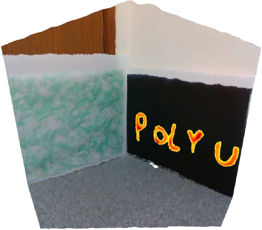
UV marker (Invisible) Heater Strip (Covered)
(a) (b)
(a) (b)
(c) (d)
(c) (d)
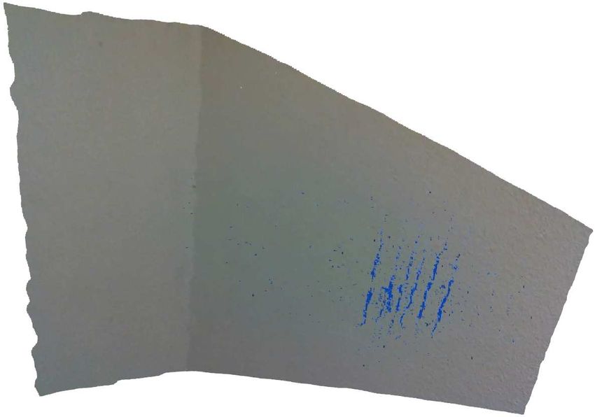
Fig. 3: Testing board and alignment testing result: (a)
- Testing board contain two part, left part test UV- Fig. 4: Different spectrum image of the wall: (a) (b) (c)
RGB alignment result,painted part is invisible for RGB (d) - RGB, thermal, UV, depth image of the wall.
camera. Right part test IR-RGB alignment result, we
covered with a black paper on heater strip during the test.
(b)(c)(d) - Testing result, point clouds of RGB-D, RGB- image on RGB image to retain most of the visible
Thermal-D (with thermal highlighted), RGB-UV-D (with spectrum information. Regarding this, we highlight
UV highlighted). the "hottest" image area of thermal image and the
"most brightness" area of UV camera on RGB image
by setting a threshold value vthres,uv and vthers,thrmal
We now have the mapping from of UV camera to respectively, take UV image for example, the equation
RGB camera. And we can also get the mapping shows below:
from thermal camera to RGB camera by using the (
same method and the calibration tool. Now, we have pu,rgb pu,uv ≤ vthres,uv
pu,rgb = (7)
aligned both UV image and thermal image to RGB pu,uv pu,uv > vthres,uv
image. We show the "hot area" as warm tones (red and
yellow) and "UV area" as cool tones (blue and
C. Fusion of Multispectral Images purple). Some image points do not have depth
Human beings are only able to see visible light. information or have invalid depth information, we call
So thermal information is typically shown as visible these points "bad points". For bad points, they cannot
colors with a colorbar to help the viewer estimate be mapped by using equation 1, so we ignore these
temperature of the area in thermal image [12]. The points which means they are still RGB points.
same for UV images. There are three color channels
III. RESULTS
(RGB, thermal, UV) and a depth channel needed
to be shown. We can visualize depth and only one A. Automatic 3D Image Alignment
color channel as point cloud. Showing only one color To test our alignment result, we build a special
channel each time will lost another two spectrum board that can both generate heat and reflect UV. This
information, a problem remains when we want to board contains two parts, one part for testing RGB-
show all spectrum together. D-thermal alignment, the other part for testing RGB-
In this paper, we present a way to show all D-UV alignment. The first part is a colored paper
spectrum information in one color channel (RGB which is painted with titanium dioxide (which can
channel). In an ordinary way, visible spectrum reflect more UV then colored paper but not affect
contains most of the useful information. We can visible light) on some special region, to show the
hardly confirm the texture of objects by using thermal school badge on UV image. The other part is heater
image (as the Fig.2(a) shows, we can not see the strip shows the word "PolyU" and covered with black
texture of the ceiling). So we only highlight some paper so that the heater strip is invisible. We find
remarkable areas by using thermal image and UV few natural UV inside room, so a UV projector is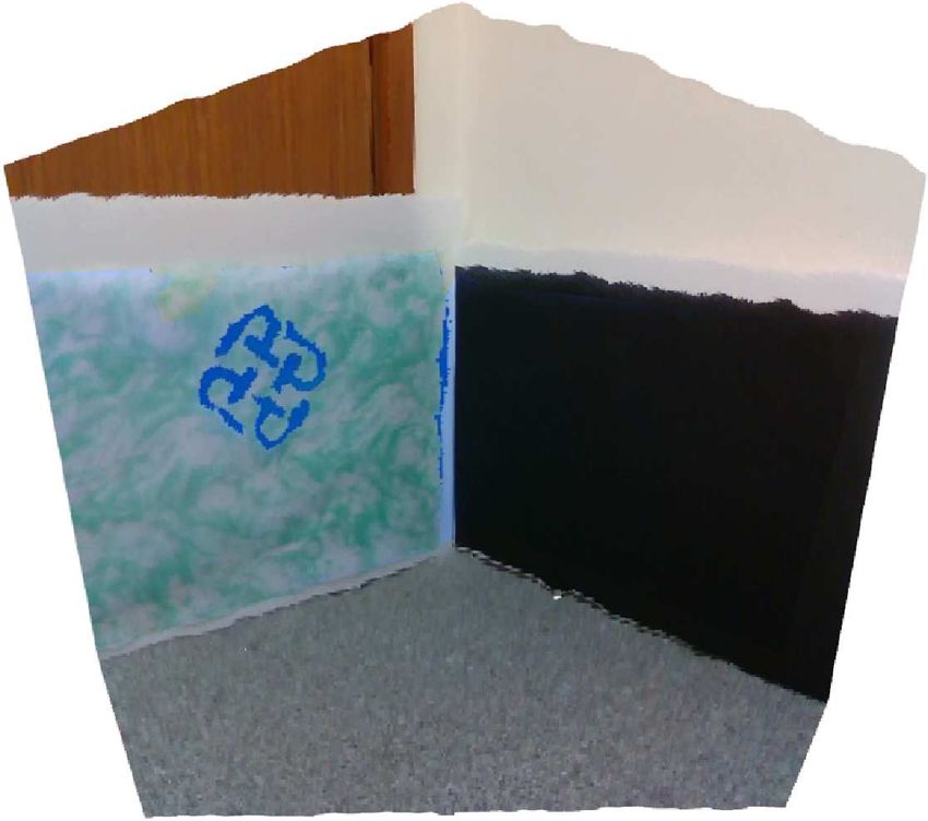
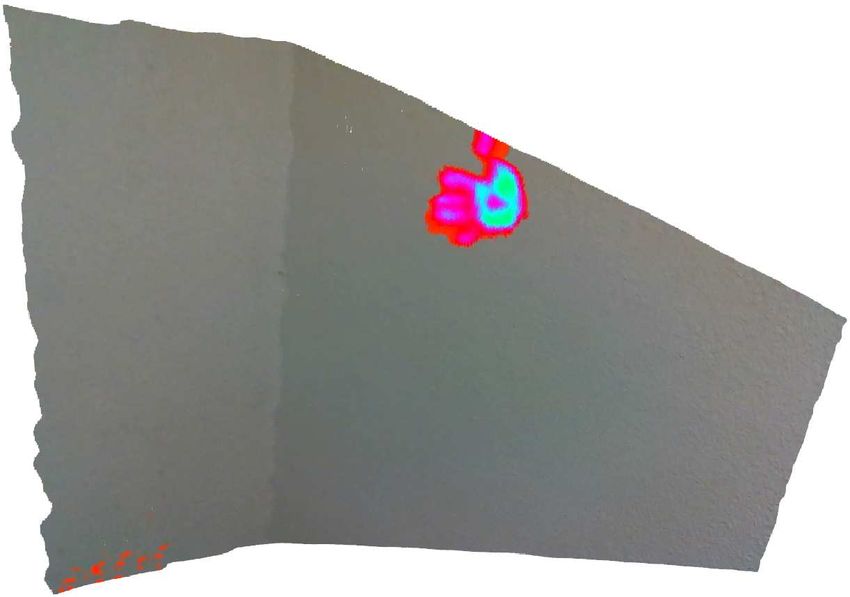
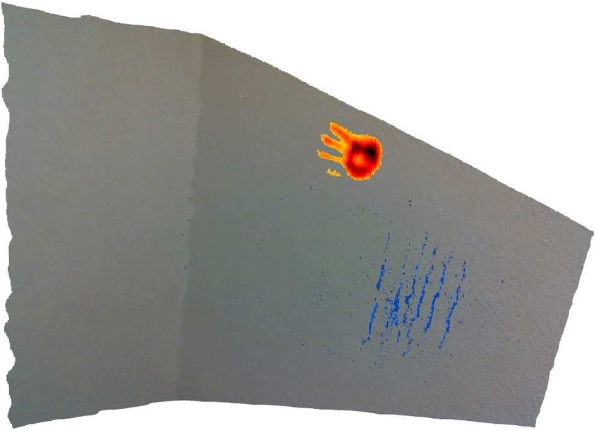
spectrum and their fusion results. Fig 5 (a) is the
                                                            point cloud of a part of the wall, with few features
                                                            shown on it. Fig 5 (b) shows the remaining heat on
                                                            the wall after someone touched and shows a hand
                                                            shape. In Fig 5 (c), we can observe some traces of
            (a)                            (b)              dried body fluid running down the wall which cannot
                                                            be seen under visible spectrum. Fig 5 (d)-(f) illustrate
                                                            the fusion results that use equation 7 for highlighting
                                                            some interest areas of thermal image and UV image,
                                                            which show some hidden features can be observed
                                                            on visible spectrum point cloud.
                                                                              IV. CONCLUSION
            (c)                            (d)                 In this article, a novel calibration tool that can
                                                            calibrate different spectrum together by using "Black
                                                            Box Effect" is designed, and a 3D multispectral vision
                                                            system that can observe the information of visible,
                                                            thermal and UV spectrum is developed. The proposed
                                                            calibration tool is easy to use and yields accurate
                                                            result of intrinsic and extrinsic parameters of cameras.
            (e)                            (f)              We then align images of each camera by using
                                                            the obtained camera parameters. By highlighting the
Fig. 5: 3D different spectrum and fusion of the wall: (a)
(b) (c) - Point clouds of RGB-D, Thermal-D, UV-D. (d)
                                                            interest area of UV and thermal images on the RGB
(e) (f) - Point clouds of RGB-thermal-D (with thermal       image, multispectral information can be emphasized
highlighted), RGB-UV-D (with UV highlighted), RGB-          in a point cloud. For future work, the developed
thermal-UV-D (with both thermal and UV highlighted).        multispectral vision system can be integrated with
                                                            the mobile robot, which monitors people’s body
                                                            temperature by the thermal camera, detects the
needed when testing. We use Open3D [13] to present          unseen containment by the UV camera, and navigates
the testing result, the testing result is shown as Fig      through the crowds by the depth camera.
3. Obviously, we have fused visible spectrum, UV,                                  R EFERENCES
thermal and depth information in one point cloud.
                                                             [1] E. Arnold, O. Y. Al-Jarrah, M. Dianati, S. Fallah, D.
                                                                 Oxtoby and A. Mouzakitis, "A Survey on 3D Object
B. Registration of “Invisible” Features                          Detection Methods for Autonomous Driving Applications,"
                                                                 in IEEE Transactions on Intelligent Transportation Systems,
   Our 3D multispectral vision system has been                   vol. 20, no. 10, pp. 3782-3795, Oct. 2019, doi:
tested in public toilet and yield good results. Some             10.1109/TITS.2019.2892405.
hidden features that cannot be observed by people’s          [2] S. Prakash, P. Y. Lee and T. Caelli, "3D Mapping of Surface
eyes are on display. We build multispectral (RGB,                Temperature Using Thermal Stereo," 2006 9th International
                                                                 Conference on Control, Automation, Robotics and Vision,
thermal, UV) point clouds of walls in the toilet.                2006, pp. 1-4, doi: 10.1109/ICARCV.2006.345342.
Our system can take down RGB, thermal, UV, and               [3] J. Sturm, N. Engelhard, F. Endres, W. Burgard and D.
depth information together at the same time and form             Cremers, "A benchmark for the evaluation of RGB-D
                                                                 SLAM systems," 2012 IEEE/RSJ International Conference
point clouds of RGB-D, Thermal-D, UV-D and RGB-
                                                                 on Intelligent Robots and Systems, 2012, pp. 573-580, doi:
Thermal-UV-D and each of them contain more than                  10.1109/IROS.2012.6385773.
306000 points. The mode of point cloud can be set            [4] Yanpeng Cao, Baobei Xu, Zhangyu Ye, Jiangxin Yang,
during our program running. We highlight the thermal             Yanlong Cao, Christel-Loic Tisse, and Xin Li, "Depth
                                                                 and thermal sensor fusion to enhance 3D thermographic
features in red and the UV features in blue. Due to              reconstruction," Opt. Express 26, 8179-8193 (2018)
limit UV inside room, the features of UV images are          [5] G. Tamburello, E.P. Kantzas, A.J.S. McGonigle, A. Aiuppa,
not easy to be separate, so we used Laplacian high-              G. Giudice,UV camera measurements of fumarole field
pass filter to sharpen the UV image, as Fig 4 (c)                degassing (La Fossa crater, Vulcano Island), Journal
                                                                 of Volcanology and Geothermal Research,Volume
shows.                                                           199, Issues 1–2, 2011,Pages 47-52,ISSN 0377-
   The Fig 5 (a)-(f) show the point cloud of each                0273,https://doi.org/10.1016/j.jvolgeores.2010.10.004.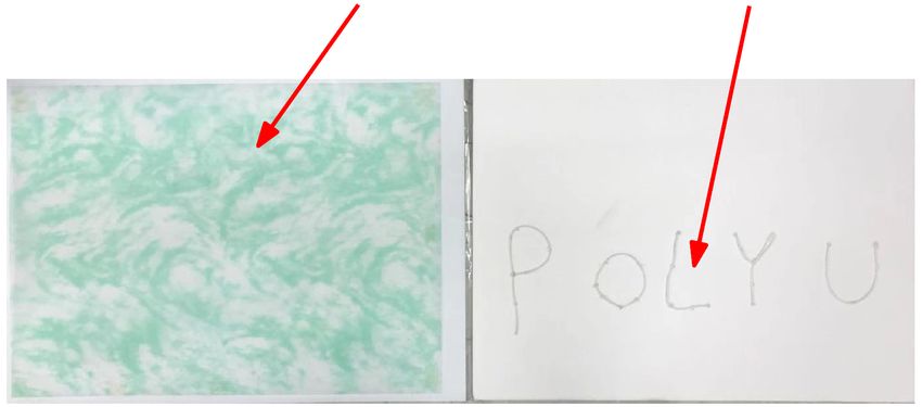
[6] FULTON, J.E., Jr. (1997), Utilizing the Ultraviolet
     (UV Detect) Camera to Enhance the Appearance of
     Photodamage and Other Skin Conditions. Dermatologic
     Surgery, 23: 163-169. https://doi.org/10.1111/j.1524-
     4725.1997.tb00013.x
 [7] S. Vidas, P. Moghadam and M. Bosse, "3D thermal
     mapping of building interiors using an RGB-D and thermal
     camera," 2013 IEEE International Conference on Robotics
     and Automation, Karlsruhe, Germany, 2013, pp. 2311-2318,
     doi: 10.1109/ICRA.2013.6630890.
 [8] S. S. Shivakumar, N. Rodrigues, A. Zhou, I. D.
     Miller, V. Kumar and C. J. Taylor, "PST900: RGB-
     Thermal Calibration, Dataset and Segmentation Network,"
     2020 IEEE International Conference on Robotics and
     Automation (ICRA), Paris, France, 2020, pp. 9441-9447,
     doi: 10.1109/ICRA40945.2020.9196831.
 [9] E. Springer, J. Almog, A. Frank, Z. Ziv, P. Bergman, W.
     Gui Qiang, Detection of dry body fluids by inherent short
     wavelength UV luminescence: preliminary results, Forensic
     Science International, Volume 66, Issue 2, 1994, Pages
     89-94, ISSN 0379-0738, https://doi.org/10.1016/0379-
     0738(94)90332-8.
[10] A. Florea and V. Fleaca, "Implementing an
     embedded system to identify possible COVID-19
     suspects using thermovision cameras," 2020 24th
     International Conference on System Theory, Control
     and Computing (ICSTCC), 2020, pp. 322-327, doi:
     10.1109/ICSTCC50638.2020.9259699.
[11] Z. Zhang, "A flexible new technique for camera
     calibration," in IEEE Transactions on Pattern Analysis and
     Machine Intelligence, vol. 22, no. 11, pp. 1330-1334, Nov.
     2000, doi: 10.1109/34.888718.
[12] Alexander Toet,Natural colour mapping for multiband
     nightvision      imagery,    Information     Fusion,Volume
     4,     Issue      3,2003,Pages      155-166,ISSN     1566-
     2535,https://doi.org/10.1016/S1566-2535(03)00038-1.
[13] Qian-Yi Zhou and Jaesik Park and Vladlen
     Koltun,Open3D:A            Modern         Library       for
     3D          Data          Processing,arXiv:1801.09847,Issue
     2018,http://arxiv.org/abs/1801.09847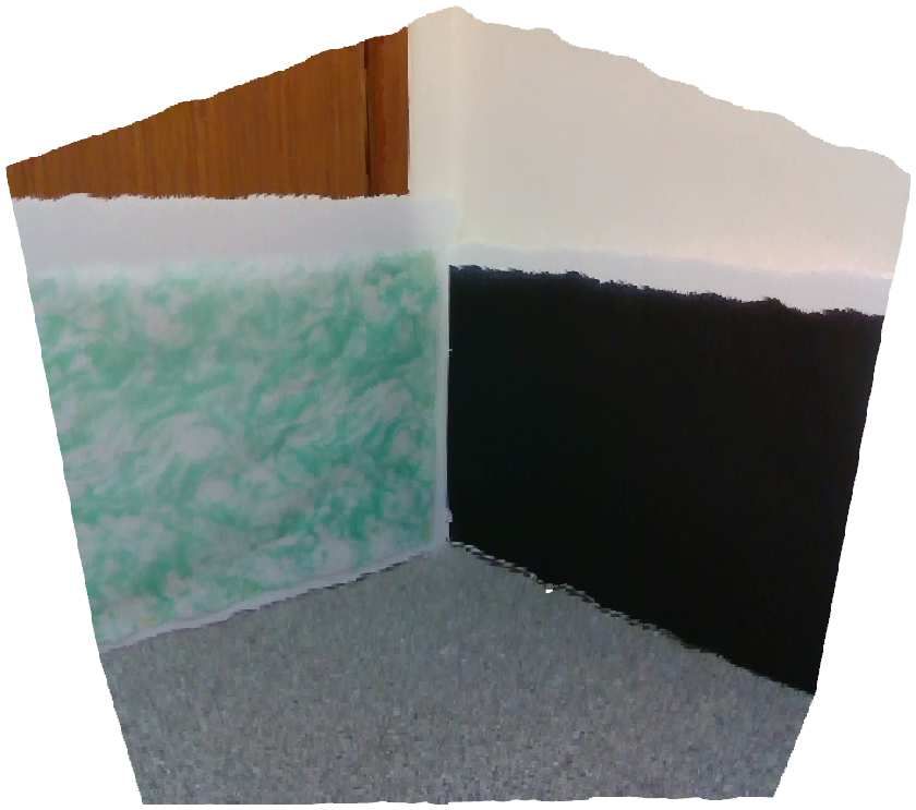
You can also read