BLK Oil/air cooler - Bühler Technologies GmbH
←
→
Page content transcription
If your browser does not render page correctly, please read the page content below

Fluidcontrol

                                                                           Oil/air cooler

                                                                                        BLK

           Installation and Operation Instructions
                                                                   Original instructions

BE350025   Bühler Technologies GmbH, Harkortstr. 29, D-40880 Ratingen
04/2022      Tel. +49 (0) 21 02 / 49 89-0, Fax: +49 (0) 21 02 / 49 89-20
                 E-Mail: fluidcontrol@buehler-technologies.com
                     Internet: www.buehler-technologies.com
Bühler Technologies GmbH, Harkortstr. 29, D-40880 Ratingen
Tel. +49 (0) 21 02 / 49 89-0, Fax: +49 (0) 21 02 / 49 89-20
Internet: www.buehler-technologies.com
E-Mail: fluidcontrol@buehler-technologies.com

Read this instruction carefully prior to installation and/or use. Pay at-
tention particularly to all advises and safety instructions to prevent in-
juries. Bühler Technologies can not be held responsible for misusing
the product or unreliable function due to unauthorised modifications.

All rights reserved. Bühler Technologies GmbH 2022

Document information
Document No.......................................................... BE350025
Version.........................................................................04/2022
BLK

Contents
1     Introduction.....................................................................................................................................................................................................................    2
      1.1   Intended use .........................................................................................................................................................................................................         2
      1.2 Model key...............................................................................................................................................................................................................         2
      1.3 Scope of delivery ..................................................................................................................................................................................................             2
2     Safety instructions......................................................................................................................................................................................................... 3
      2.1 Important advice ................................................................................................................................................................................................. 3
      2.2 General hazard warnings ................................................................................................................................................................................. 4
3     Transport and storage .................................................................................................................................................................................................. 5
4     Installation and connection ........................................................................................................................................................................................ 6
      4.1 Requirements to the installation site............................................................................................................................................................ 6
      4.2 Installing the unit................................................................................................................................................................................................ 6
            4.2.1   Installing swivel nuts in the fitting body ..................................................................................................................................... 6
      4.3 Hydraulic connection ......................................................................................................................................................................................... 7
      4.4 Electrical connections ........................................................................................................................................................................................ 7
            4.4.1   Electrical connections BLK 1-phase ................................................................................................................................................. 8
            4.4.2 Electrical connection temperature switch TSA........................................................................................................................... 8
5     Operation and control ................................................................................................................................................................................................ 10
      5.1 Before starting ................................................................................................................................................................................................... 10
      5.2 During starting .................................................................................................................................................................................................. 10
6     Maintenance................................................................................................................................................................................................................... 11
      6.1 Cleaning and disassembly of the cooler matrix....................................................................................................................................... 12
      6.2 Cleaning the cooler matrix inside ................................................................................................................................................................. 13
      6.3 Cleaning the fan case ........................................................................................................................................................................................ 13
      6.4 Replacing fan parts............................................................................................................................................................................................ 13
7     Service and repair......................................................................................................................................................................................................... 14
      7.1 Troubleshooting ................................................................................................................................................................................................ 14
8     Disposal ............................................................................................................................................................................................................................ 15
9     Appendices..................................................................................................................................................................................................................... 16
      9.1 Technical data .................................................................................................................................................................................................... 16
          9.1.1    Basic data (at 50 Hz frequency) ...................................................................................................................................................... 17
          9.1.2    Performance curves frame size 1-4................................................................................................................................................ 17
          9.1.3    Performance curves frame size 5-7................................................................................................................................................ 18
          9.1.4    Performance curves frame size 8-10 ............................................................................................................................................. 18
      9.2 Dimensions ......................................................................................................................................................................................................... 19
      9.3 Functional diagram ......................................................................................................................................................................................... 20
      9.4 Installation torques and clamping range for cable fitting ................................................................................................................... 21
      9.5 Screw torques ..................................................................................................................................................................................................... 21
      9.6 Hose torques ....................................................................................................................................................................................................... 21
      9.7 Calculations ........................................................................................................................................................................................................ 21
          9.7.1    Calculating viscosity .......................................................................................................................................................................... 21
          9.7.2 Table of operational viscosity for VG oil ..................................................................................................................................... 22
          9.7.3 Calculating the pressure loss ......................................................................................................................................................... 22
      9.8 Pressure loss in straight pipes....................................................................................................................................................................... 22
10 Attached documents ................................................................................................................................................................................................... 24

BE350025 ◦ 04/2022                                                                                                                                                                       Bühler Technologies GmbH                           i
BLK

1 Introduction

1.1 Intended use
BLK oil/air coolers are suited for the cooling of oils in hydraulic and lubrication systems. Their scope is given by their specifica-
tions. The use in other applications is not permitted without confirmation by Bühler Technologies GmbH.

1.2 Model key
 BLK 4.6- IBx - T50

                          Number of motor contacts
                          Frame size
                         To also have a bypass and/or thermal contact, the specification will be added to the type
    BLK 4.6- IBx - T50   designation:

                          Bypass version           AB      (BLK 2-10)    external bypass
                                                   IB      (BLK 3-9)     internal bypass
                                                   ITB     (BLK 3-9)     internal temperature-dependent bypass 2 bar / 45 °C
                                                   ATB     (BLK 2-9)     external temperature-dependent bypass 2 bar / 45 °C
                                                   x                     bypass value 2 bar, 5 bar, 8 bar

                          Temperature switch       T50, T60              Temperature in °C, specification see
                                                   T70, T80              separate data sheet

1.3 Scope of delivery
– 1 x Oil/air cooler
– Product documentation

2     Bühler Technologies GmbH                                                                                       BE350025 ◦ 04/2022
BLK

2 Safety instructions

2.1 Important advice
Operation of the device is only permitted if:
– the product is used under the conditions described in the installation- and operation instruction, the intended application
  according to the type plate and the intended use. In case of unauthorized modifications done by the user Bühler Technolo-
  gies GmbH can not be held responsible for any damage,
– when complying with the specifications and markings on the nameplates.
– the performance limits given in the datasheets and in the installation- and operation instruction are obeyed,
– monitoring devices and safety devices are installed properly,
– service and repair is carried out by Bühler Technologies GmbH,
– only original spare parts are used.
This manual is part of the equipment. The manufacturer keeps the right to modify specifications without advanced notice. Keep
this manual for later use.

Signal words for warnings
                     Signal word for an imminent danger with high risk, resulting in severe injuries or death if not avoided.
    DANGER

                     Signal word for a hazardous situation with medium risk, possibly resulting in severe injuries or death if not
    WARNING
                     avoided.

                     Signal word for a hazardous situation with low risk, resulting in damaged to the device or the property or
    CAUTION
                     minor or medium injuries if not avoided.

                     Signal word for important information to the product.
     NOTICE

Warning signs
In this manual, the following warning signs are used:

         Warning against hazardous situations                           Warning against high pressure

         Warning against electrical voltage                             Warning against potentially explosive atmospheres

         Warning against hot surface                                    General notice

         Warning against environmental hazard                           Disconnect from mains

         Warning against rotating parts                                 Wear protection gloves

BE350025 ◦ 04/2022                                                                                    Bühler Technologies GmbH       3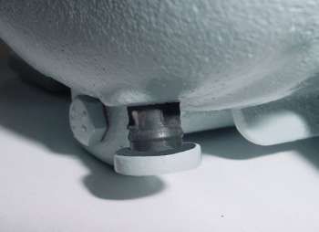
BLK

2.2 General hazard warnings
The equipment must be installed by a professional familiar with the safety requirements and risks.
Be sure to observe the safety regulations and generally applicable rules of technology relevant for the installation site. Prevent
malfunctions and avoid personal injuries and property damage.

The operator of the system must ensure:
– Safety notices and operating instructions are available and observed,
– The respective national accident prevention regulations are observed,
– The permissible data and operational conditions are maintained,
– Safety guards are used and mandatory maintenance is performed,
– Legal regulations are observed during disposal,
– compliance with national installation regulations.
– Nearby equipment is EMC protected, e.g. through shielding.
– The current and voltage supply for the aggregate has a (mains) separator with adequate switching capacity. National re-
  quirements must be observed.

Maintenance, Repair
Please note during maintenance and repairs:
– Repairs to the unit must be performed by Bühler authorised personnel.
– Only perform conversion-, maintenance or installation work described in these operating and installation instructions.
– Always use genuine spare parts.
– Do not install damaged or defective spare part. If necessary, visually inspect prior to installation to determine any obvious
  damage to the spare parts.
Always observe the applicable safety and operating regulations in the respective country of use when performing any type of
maintenance.

      DANGER          Electrical voltage
                      Electrocution hazard.
                      a) Disconnect the device from power supply.
                      b) Make sure that the equipment cannot be reconnected to mains unintentionally.
                      c) The device must be opened by trained staff only.
                      d) Regard correct mains voltage.

      CAUTION         Hot surface
                      Burning hazard
                      Let the device cool down before maintaining.

      CAUTION         High pressure
                      Hazard of injury due to flung off parts or oil, environmental hazard due to oil.
                      a) Before starting any maintenance or repair to the oil circuit, make sure that the device
                         is depressurized. This applies to the threaded plugs as well.
                      b) Avoid environmental pollution (oil spills) during cleaning or maintenance of the oil
                         circuit.
                      c) Use drip pans.

      DANGER          Potentially explosive atmosphere
                      Explosion hazard if used in hazardous areas.
                      The device is not suitable for operation in hazardous areas with potentially explosive at-
                      mospheres.

4   Bühler Technologies GmbH                                                                                       BE350025 ◦ 04/2022
BLK

3 Transport and storage
Only transport the product inside the original packaging or a suitable alternative. Ensure secure fastening and mooring.
Air coolers have M10 eye bolts at the top of the cooler housing for transport. Please note, due to the variety of versions the
mounting bracket is not located at the exact centre of gravity and the cooler may swing when hoisted. Never hoist the complete
cooler by the M8 threads in the cooling elements!
Only use the motor transport eyes to hoist the motor without add-ons.
Do not use the eye bolts according to DIN 580 in ambient temperatures below -20 °C. The eye bolts could fracture in these tem-
peratures, injuring personnel and/or damage the system.
Do not strain the eye bolts more than 45° in the thread direction.
When not in use, the equipment must be protected from moisture and heat. It must be stored in a covered, dry, dust-free room
at room temperature.

     WARNING          Crushing hazard
                      Crushing hazard during equipment transport and set-up.
                      Use the correct hoisting gear to prevent injuries during hoisting.
                      Be sure the hoisting gear is free from defects and approved for the weight of the device.
                      Ensure secure fastening and mooring when transporting.

BE350025 ◦ 04/2022                                                                                   Bühler Technologies GmbH    5
BLK

4 Installation and connection

4.1 Requirements to the installation site
Aggregate
The aggregate must be set up to allow for unobstructed air flow and adequate room for maintenance/repairs. When installed
outdoors, be sure to consider the motor protection rating (standard: IP 55) and ensure adequate protection from the weather.

Air cooler
The aggregate must be set up to allow for unobstructed air flow and adequate room for maintenance/repairs.
The cooler must be located in such a way that the air flowing through the matrix has free flow on entry and exit. The distance
between air intake or air outlet to the nearest surrounding obstacle should be at minimum half the height of the matrix. Free
air flow must be provided.If the cooler is to be sited near to working personnel, the effect of hot draught and noise emissions
must be taken into account.
If the cooler is installed in closed space, ensure sufficient air circulation. Avoid back flow of warmed air. If necessary, the room
must be vented.
Due to lower temperatures with respect to closed rooms, the cooling capacity outside raises, but on the other hand higher start
up pressure may result due to higher oil viscosity. In this case, consider a bypass valve and / or a heating.
The rotating fan might lead to static charging. Therefore sensitive equipment like electronics should be kept away from the
device.

4.2 Installing the unit
The units are screwed in place at the attachment points using screws. Be sure the support structure is sized adequately. To pro-
tect the system from damage, the connections must be stress free. We recommend using flexible hoses. Be sure the hose is
stable against negative pressure, e.g. steel wire reinforced. Avoid possible leaks in the circuit to prevent environmental dam-
ages. If necessary, use an oil pan. Protect the aggregate from mechanical impact.

4.2.1 Installing swivel nuts in the fitting body
Proceed as follows:
– Carefully slide the preinstalled pipe end into the 24° cone on the fitting body.
– Tighten the swivel nut until a considerable increase in force can be felt (fixed point).
– Use a suitable spanner to tighten the swivel nut a 1/12 turn more (30°) beyond the fixed point. A marker line on the swivel
  nut and the fitting body facilitates observing the correct tightening angle.

     Tube          Thread           Torque (Nm) for straight          Torque (Nm) sealing plug
     A.D.                                screwed plug
      6               G 1/8"                    18                                13
      8               G 1/4"                    35                                30
      10              G 1/4"                    35                                30
      12              G 3/8"                    70                                60
      15              G 1/2"                   90                                 80
      18              G 1/2"                   90                                 80
      22              G 3/4"                   180                                140
      28               G 1"                    310                               200
      35           G 1 1/4"                    450                               400
      42           G 1 1/2"                    540                               450

6   Bühler Technologies GmbH                                                                                        BE350025 ◦ 04/2022
BLK
4.3 Hydraulic connection
Carry out the hydraulic connection as described in the attached data. Connect the lines stress and vibration free, so typically us-
ing hoses.
Be sure to use suitable lines (with regard to pressure, fluid resistance, environmental influences, fire) when connecting to the
hydraulic-, lubrication circuit. Tighten the hose lines with a suitable torque (see appendix).
Contaminated fluids impact the life of the cooling system, we therefore recommend a purity class of minimum 3/19/13 per
ISO 4406.
If your hydraulic system is equipped with control or shut-off valves, we recommend protecting the cooling system with a pres-
sure relief valve. No pressure relief valves are factory installed in the cooler.
When installing an air cooler in return lines, sudden changes to the flow rate can potentially cause significant pressure peaks
which even safety relief valves cannot dampen. The limits for the static pressure must not exceed max. 21 bar, or 15 bar for dy-
namic pressure peaks. Otherwise an off-line cooler must be used.
The coolers are optionally available with external or internal bypass valve in the cooling matrix.
4.4 Electrical connections
CAUTION Electrical voltage
Wrong mains voltage may damage the device.
Installation of the device shall be performed by trained staff only. Regard the voltage
given on the type plate. Make sure that the cables have sufficient strain relief.
Fusing
Fusing has to be done due to local standards!
Polarity
Take care of the directional rotation of the motor. The fan rotates counter clockwise
when regarded form the motor’s side!
Watch the direction arrow on the sticker.
The direction of rotation can be changed by reversing any two phases.
Use the applicable local regulations to determine the safety values and the cross-sections of connection leads. The motor and, if
equipped, starting devices must be connected to protective earth.
Lead fuses protect the cables in case of a short circuit, but are not sufficient to protect the motor coils from burning due to over-
load. Therefore, install an adequate motor circuit breaker with high precision range of adjustment for thermal protection to pro-
tect the motor against overload and operation with two phases
Adjust the motor circuit breaker according to the nominal value specified on the type plate of the motor. Operation outside the
specified mains voltage and frequency range limits is prohibited.
Take appropriate measures to protect energised parts from being touched by persons and/or interference from foreign objects.
The operator of the equipment is responsible for ensuring lightning protection.
Connect the protective earth of the motor to the protective earth on site. Protective earth per DIN VDE 0100 must be connected
to the marked earth lead terminal.
BE350025 ◦ 04/2022 Bühler Technologies GmbH 7BLK
4.4.1 Electrical connections BLK 1-phase
U1 blue Z brown
U2 black PE green-yellow
4.4.2 Electrical connection temperature switch TSA
The temperature switch TSA is installed in a cooling circuit with an oil/air cooler BLK as a typical application. Through reaching
the switching temperature the fan-motor is switched-on and the oil will be cooled. After falling under the hysteresis the motor
shuts off.
If the cooling matrix has an optional temperature contact type TSA, the maximum values (see below) must not be exceeded. If
connecting it to a relay, a free wheel circuit has to be added. Carry out the connection according to the following specifications
(numbering inside the connector):
Terminal 1 – 2 Contacts
Terminal 3 Not used (except for BLK 1)
Terminal PE Protective earth (not BLK 1)
Temperature switch TSA T50 switching temperature 50 °C
T60 60 °C
T70 70 °C
max. voltage 230 V AC/D
max. switching current 2 A, contact load max. 100 VA
switching function NC
Hysteresis approx. 10 °C
protection class IP 65
Temperature switch TS-BLK1 T50 switching temperature 50 °C
T60 60 °C
T70 70 °C
T80 80 °C
voltage / switching temperature 12 V DC / 10 A
24 V DC / 5 A
switching function NO
Hysteresis approx. 5 °C
protection class IP 20
8 Bühler Technologies GmbH BE350025 ◦ 04/2022BLK
Example wiring with temperature switch
F1 Fuse K1 Relay
F2 Fuse K2 Circuit breaker
F3 Fuse S1 Protecting device
H1 Mains switch S2 Protecting device
Relay, circuit breaker and protecting devices are not part of the delivery.
BE350025 ◦ 04/2022 Bühler Technologies GmbH 9BLK
5 Operation and control
WARNING Danger due to rotating fan
Injuries to the hand may occur. Do not reach into the safety guard!
NOTICE
The device must not be operated beyond its specifications.
NOTICE
Abrupt flow variation can lead to pressure peaks that may damage the cooler matrix.
Make sure that the specifications are not exceeded in this case!
5.1 Before starting
– Check that all parts are free of damage, especially the cooling element and fan guard. Do not put a damaged device into op-
eration.
– Check if the two warning labels (rotating parts) on the cooler’s housing are fitted.
– Check the correct connections of oil and power circuits according to chapter „Installation and connection“.
– Make sure that all valves or other parts in the cooling circuit, which have to be opened, are opened.
5.2 During starting
First, check that the motor is proper electrically connected and the fan rotates counter clockwise when looking from the motor’s
side.
CAUTION Hot surface
Burning hazard
Let the device cool down before maintaining.
CAUTION High pressure
Hazard of injury due to flung off parts or oil, environmental hazard due to oil.
a) Before starting any maintenance or repair to the oil circuit, make sure that the device
is depressurized. This applies to the threaded plugs as well.
b) Avoid environmental pollution (oil spills) during cleaning or maintenance of the oil
circuit.
c) Use drip pans.
Noise level
The coolers, which are supplied with an additional circulation pump, have a low noise. If the noise level increases significantly
over the listed value, this could be caused through improper installation of the cooler, specially of the suction line. The technical
consultants from Bühler Technologies GmbH will be happy to assist you.
10 Bühler Technologies GmbH BE350025 ◦ 04/2022BLK
6 Maintenance
During maintenance, remember:
– The equipment must be maintained by a professional familiar with the safety requirements and risks.
– Only perform maintenance work described in these operating and installation instructions.
– When performing maintenance of any type, observe the respective safety and operation regulations.
DANGER Electrical voltage
Electrocution hazard.
a) Disconnect the device from power supply.
b) Make sure that the equipment cannot be reconnected to mains unintentionally.
c) The device must be opened by trained staff only.
d) Regard correct mains voltage.
CAUTION Hot surface
Burning hazard
Let the device cool down before maintaining.
CAUTION High pressure
Hazard of injury due to flung off parts or oil, environmental hazard due to oil.
a) Before starting any maintenance or repair to the oil circuit, make sure that the device
is depressurized. This applies to the threaded plugs as well.
b) Avoid environmental pollution (oil spills) during cleaning or maintenance of the oil
circuit.
c) Use drip pans.
Under normal operating conditions the aggregates are maintenance free. Preventive maintenance must therefore be routinely
carried out by the operating company.
When doing so, please pay attention to:
– Tight screw fittings,
– Tightness,
– Damage to the aggregate (replace damaged parts),
– Abnormal (unusual) noise and vibration,
– Cooler matrix cleanliness. Dirt on the cooler matrix reduces the cooling capacity,
– Check warning labels for legibility and damage.
Electrical connections must be checked annually by a licensed electrician.
The external parts the motors, particularly the cooling ribs and cooling ducts as clean as possible to prevent compromising heat
release.
Please note the specified protection against dust and moisture. Pressure cleaning is only permitted if the motor has the respect-
ive protection rating.
The motors feature ball bearings sealed on both sides. The grease filling is designed to last for the life of the unit. Greasing is not
necessary.
The motor mounts may only be replaced by Bühler Technologies GmbH or a qualified specialist company.
BE350025 ◦ 04/2022 Bühler Technologies GmbH 11BLK
Condensate drain holes at motors from manufacturer WEG
If the motor is used in surrounding with high humidity this could lead, depending on the ambient temperature, to formation of
condensate inside the motor housing. Specially at longer nonoperation period. The motors of WEG have a condensate drain plug
which can be used for draining off. Pull out the plug according to the pictures and push it then back. If the plug is not pushed
back or completely removed, the motor losses the IP degree of protection.
Condensate drain bore
(plug)
closed position open position plug
6.1 Cleaning and disassembly of the cooler matrix
Due to the design of the cooling fins, the cooler has low susceptibility to dust and dirt. Normally, it is sufficient to clean the front
surface with a brush. If the ambient air is loaded with higher amounts of oil or dust, it may be necessary to clean the cooling
matrix in regular intervals.
– First, let the cooling matrix cool down. Then disconnect the motor from the mains and secure it against reconnecting.
– Depressurize the system and disconnect the piping. Place an oil drip pan below the cooling matrix to collect leaking oil.
– Close all connections with plugs to avoid further oil leakage.
– Protect the cooling matrix from falling down.
– Dismantle the cooling matrix from the fan case by loosening the 4 fastening bolts. The cooler sizes 6 up to 8 provide threads
for eyebolts in the cooler matrix for lifting with hoisting devices.
– Take it to the cleaning area. Be careful not to damage the fins during transport and cleaning.
– Clean the matrix by blowing pressurized air from the rear side through the fin rows in parallel.
– If dirt is wet and sticky, carefully use high pressure cleaner and/or some washing agent. In this case, rinse the cooler matrix
with pure water.
– Remount the cooling matrix in reverse order.
– Regard correct mounting of the connecting sleeves.
12 Bühler Technologies GmbH BE350025 ◦ 04/2022BLK 6.2 Cleaning the cooler matrix inside In the event of deposits in the cooling matrix due to inadequate filtration, you may try to remove these as follows after cleaning the outside: – Remove the cooler matrix as described in “Cooler matrix cleaning and disassembly”. – Add degreaser and close all connections of the cooler matrix with plugs. – After allowing the degreaser to sit for a while, drain and flush the cooler matrix with clean fluid. Dispose of the degreaser and flushing oil as required by law. – After cleaning, remount the cooler matrix in reverse order. 6.3 Cleaning the fan case Due to the design, dust and dirt will not deposit in a large amount inside the fan case. Nevertheless, any deposits of dirt should be blown out each time the cooler is cleaned. 6.4 Replacing fan parts – Disconnect the motor from the mains and protect it from being re-connected unintentionally. – Now remove the mains cable. – There are two different fan models. – Model with fixed fan hub, the fan can be replaced only together with the hub. – Models with separated hub and fan, the fan can be replaced without replacing the hub. Models without motor support: – Secure the fan unit against falling. – Then unscrew the four fixing bolts at the case on top of the fan guard. – Now you can pull out the fan unit carefully to the back. – Remount the new fan in reverse order. If the fan is replaced, insert the screw adding with glue at the motor shaft. Models with motor support and mounting brackets: – Secure the fan unit against falling. – Unscrew the four fixing bolts at the case on top of the mounting brackets. – Unscrew the four screws connecting the fan unit to the housing at the tips of the fan guard. – The fan unit can now be pulled out carefully to the back. – Remount the new fan in reverse order. If the fan is replaced, insert the screw adding with glue at the motor shaft. Models with motor support and elongated holes in the mounting rails: – Secure the fan unit against falling. – Unscrew the screws fixing the support to the coolers feet about two revolutions. – Unscrew the four screws connecting the fan unit to the housing at the tips of the fan guard. – The fan unit can now be pulled out carefully to the back. – Remount the new fan in reverse order. If the fan is replaced, insert the screw adding with glue at the motor shaft. Models with motor brackets and holes in the mounting rails: – Secure the fan unit against falling. – Unscrew the screws fixing the support to the coolers feet about two revolutions. – Unscrew the four screws connecting the fan unit to the housing at the tips of the fan guard. – The fan unit can now be pulled out carefully to the back. – Remount the new fan in reverse order. If the fan is replaced, insert the screw adding with glue at the motor shaft. BE350025 ◦ 04/2022 Bühler Technologies GmbH 13
BLK

7 Service and repair
This chapter contains information on troubleshooting and correction should an error occur during operation.
Repairs to the unit must be performed by Bühler authorised personnel.
Please contact our Service Department with any questions:
Tel.: +49-(0)2102-498955 or your agent
If the equipment is not functioning properly after correcting any malfunctions and switching on the power, it must be inspected
by the manufacturer. Please send the equipment inside suitable packaging to:
Bühler Technologies GmbH
- Reparatur/Service -
Harkortstraße 29
40880 Ratingen
Germany
Please also attach the completed and signed RMA decontamination statement to the packaging. We will otherwise be unable to
process your repair order.
You will find the form in the appendix of these instructions, or simply request it by e-mail:
service@buehler-technologies.com.

7.1 Troubleshooting
           Problem / Failure                       Possible cause                                       Solution
Cooling capacity not sufficient   – Ambient air temperature is higher than        – Select larger model
                                    specified
                                  – Motor’s rotation direction wrong              – Correct connection, see Electrical connec-
                                                                                    tions
                                  – Motor doesn’t start                           – Correct connection, see Electrical connec-
                                                                                    tions
                                  – Air flow too low                              – Correct connection, see Electrical connec-
                                                                                    tions
                                  – Air fins clogged                              – Clean cooler matrix, see Maintenance
                                  – Near obstacles                                – Regard minimum distance
                                  – Oil flow too low                              – Increase oil flow
                                  – Oil channel clogged                           – Cleaning, see chapter Cleaning the cooler
                                                                                    matrix inside
                                  – Oil circuit blocked                           – Open valves and cocks
Tab. 1: Troubleshooting

14   Bühler Technologies GmbH                                                                                      BE350025 ◦ 04/2022
BLK 8 Disposal Dispose of the parts in such a way that does not present a danger to other people’s heath or to the environment. Observe the legal requirements in the country of use for the disposal of electrical components and oils and coolants. BE350025 ◦ 04/2022 Bühler Technologies GmbH 15
BLK

9 Appendices

9.1 Technical data
Technical Data
Materials / surface protection
Cooling battery:                                    Aluminium, painted
ventilation box, safety guard and motor brackets:   Steel, powder-coated
Colour:                                             RAL 7001 / Motor: RAL 7024/7030
Operating fluids:                                   Mineral oils according to DIN 51524
                                                    Gear lubricant according to DIN 51517-3
                                                    Oil/water emulsions HFA and HFB according to CETOP RP 77 H
                                                    Water glycol HFC according to CETOP RF 77 H
                                                    Phosphoric ester HFD-R according to CETOP RP 77 H
Operating pressure
static
BLK 1.2:                                            max. 16 bar
BLK 2.2 – BLK 10.8:                                 max. 21 bar
dynamic
BLK 1.2:                                            11 bar (at 5 M load cycle, 3 Hz)
BLK 2.2 – BLK 10.8:                                 15 bar (at 5 M load cycle, 3 Hz)
Operating oil temperature:                          max. 80 °C (higher upon request)
Ambient temperature:                                -15 to +40 °C

Electric motors (others available upon request)
Voltage / frequency:
BLK 1.2:                                            230 V - 50 Hz
BLK 2.2 – BLK 10.8:                                 220/380 – 245/420V 50Hz
                                                    220/380 – 280/480V 60Hz
Thermal stability:                                  Insulation class F,
                                                    utilisation per Class B
Protection class:
BLK 1.2:                                            IP44
BLK 2.2 – BLK 10.8:                                 IP55
The motors comply with standards
IEC 60034, IEC 60072, IEC 60085

16   Bühler Technologies GmbH                                                                        BE350025 ◦ 04/2022
BLK
9.1.1 Basic data (at 50 Hz frequency)
Item no. Cooler type Motor power Weight Capacity Noise level
Number of poles (kg) (L) db(A)*
Rated current at 400 V
3501200 BLK 1.2 0,05 kW / 2 / 0,24 A (230 V) 7 0,8 65
3502200IE3 BLK 2.2 0,55 kW / 2 / 1,3 A 25 1,3 81
3502400IE3 BLK 2.4 0,18 kW / 4 / 0,5 A 23 1,3 66
3503200IE3 BLK 3.2 1,1 kW / 2 / 2,3 A 34 1,8 87
3503400IE3 BLK 3.4 0,25 kW / 4 / 0,7 A 29 1,8 71
3504400IE3 BLK 4.4 0,37 kW / 4 / 1,0 A 33 2,3 73
3504600IE3 BLK 4.6 0,18 kW / 6 / 0,7 A 31 2,3 63
3505400IE3 BLK 5.4 0,75 kW / 4 / 1,9 A 48 3,1 79
3505600IE3 BLK 5.6 0,25 kW / 6 / 0,8 A 40 3,1 68
3506410IE3 BLK 6.4 2,2 kW / 4 / 4,6 A 77 4,1 86
3506610IE3 BLK 6.6 0,55 kW / 6 / 1,5 A 64 4,1 74
3507410IE3 BLK 7.4 2,2 kW / 4 / 4,6 A 88 5,4 89
3507610IE3 BLK 7.6 0,55 kW / 6 / 1,5 A 72 5,4 75
3508610IE3 BLK 8.6 1,5 kW / 6 / 3,8 A 104 6,3 79
3508810IE3 BLK 8.8 0,55 kW / 8 / 1,9 A 90 6,3 73
3509610IE3 BLK 9.6 2,2 kW / 6 / 5,6 A 158 8,2 86
3509810IE3 BLK 9.8 1,1 kW / 8 / 3,0 A 141 8,2 79
3510610IE3 BLK 10.6 5,5 kW / 6 / 12,8 A 258 19 90
3510810IE3 BLK 10.8 2,2 kW / 8 / 5,9 A 246 19 84
The item numbers for BLK 2.2-5.6 are 50/60 Hz versions, for BLK 6.4-10.8 only the 50 Hz version, please contact us for the 60 Hz version.
*DIN EN ISO 3744, Class 3
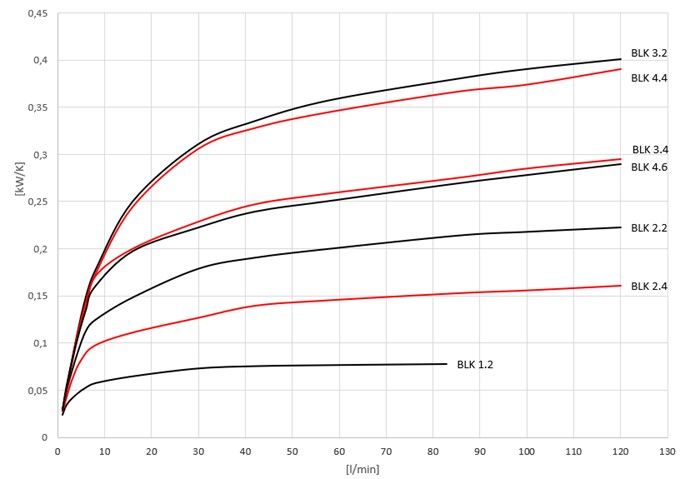
9.1.2 Performance curves frame size 1-4
BE350025 ◦ 04/2022 Bühler Technologies GmbH 17BLK 9.1.3 Performance curves frame size 5-7 9.1.4 Performance curves frame size 8-10 18 Bühler Technologies GmbH BE350025 ◦ 04/2022
BLK

9.2 Dimensions

                                                                                                    Air

MB        on some models the motors are mounted with a bracket
*         on BLK 9 and 10 = 150 mm
**        Connection fitting on BLK 9 and 10 only

Model        A       B      C       D       E      F      G      H          J                K     L       M      N       O     MB
BLK 1.2      315     244    190     62,5    144   165     -      -          2x G1/2          7     20      50    33      45     -
BLK 2.2      370     370    203     83,5    416   510     -      25         2x G1            9     33      125   106     67     -
BLK 2.4      370     370    203     83,5    396   510     -      25         2x G1            9     33      125   106     67     -
BLK 3.2      440     440    203     118,5   464   510     230    25         3x G1            9     33      150   105     67     -
BLK 3.4      440     440    203     118,5   441   510     230    25         3x G1            9     33      150   105     67     -
BLK 4.4      500     500    203     148,5   466   510     230    25         3x G1            9     33      175   104     67     -
BLK 4.6      500     500    203     148,5   466   510     230    25         3x G1            9     33      175   104     67     -
BLK 5.4      580     580    356     112     514   510     305    23,5       3x G1            9     33      200   100     67     -
BLK 5.6      580     580    356     112     491   510     305    23,5       3x G1            9     33      200   100     67     -
BLK 6.4      700     700    356     172     612   510     410    9,5        3x G1 1/4        9     33      225   110     67     x
BLK 6.6      700     700    356     172     539   510     410    9,5        3x G1 1/4        9     33      225   110     67     x
BLK 7.4      700     840    356     172     637   510     590    9,5        3x G1 1/4        9     33      250   91      67     x
BLK 7.6      700     840    356     172     564   510     590    9,5        3x G1 1/4        9     33      250   91      67     x
BLK 8.6      870     870    508     181     651   510     585    11         3x G1 1/4        12    33      275   101,5   67     x
BLK 8.8      870     870    508     181     625   510     585    11         3x G1 1/4        12    33      275   101,5   67     x
BLK 9.6      1010    1020   518     246     714   890     822    3          4x G1 1/2        12    78      300   99      67     x
BLK 9.8      1010    1020   518     246     692   890     822    3          4x G1 1/2        12    73      300   99      67     x
BLK 10.6     1185    1185   600     292,5   852   910     940    5          4x SAE 2 1/2     12    73      325   130     94     x
BLK 10.8     1185    1185   600     292,5   815   910     940    5          4x SAE 2 1/2     12    73      325   130     94     x

BLK 1

                                                                      Air

                                                                                        internal motor

BE350025 ◦ 04/2022                                                                                        Bühler Technologies GmbH   19
BLK
9.3 Functional diagram
Standard version BLK 2 Standard version BLK 1, 3 to BLK 10
Direction of flow left to right or vice versa. Direction of flow top left to bottom right or the exact opposite.
The oil outlet is always on the opposite side. The second con-
nection must be closed.
Internal bypass IB/ ITB (BLK 3-9) External bypass AB (BLK 2-10) / ATB (BLK 2-9)
The oil inlet and outlet are always on the same side. Connec- Oil inlet always at the bottom. Other connections must be
tions on the opposite side must be closed. closed. Oil outlet always on the opposite side.
With bypass valve With temperature-dependent bypass valve
With temperature switch attached
20 Bühler Technologies GmbH BE350025 ◦ 04/2022BLK
9.4 Installation torques and clamping range for cable fitting
Strain relief clamping Installation torque (Nm)
Size range (mm)
M12x1,5 3-6 1,5
M16x1,5 5-9,5 2,5
M20x1,5 8-13 3,5
M25x1,5 11-17 5
M32x1,5 15-21 5
M40x1,5 19-28 7,5
M50x1,5 27-35 7,5
M63x1,5 32-42 13
9.5 Screw torques
Thread Torque (Nm)
M5 4
M6 8
M8 15
M10 30
M12 51
9.6 Hose torques
Connections/mounts Torque (Nm)
Hose connections DN20 180
Hose connections DN25 250
Hose connections DN32 350
9.7 Calculations
9.7.1 Calculating viscosity
Valid for VG-oil between 10 - 100 °C at an exactness from ± 5 %.
Definitions Example: oil VG 46
V40 oil viscosity at 40 °C in cst V40 46 cst
T temperature in °C T 25 °C
ʋ viscosity in cst
BE350025 ◦ 04/2022 Bühler Technologies GmbH 21BLK
9.7.2 Table of operational viscosity for VG oil
10 °C 20 °C 30 °C 40 °C 50 °C 60 °C 70 °C 80 °C 90 °C
VG 46 264,45 131,96 73,58 46,00 29,13 20,04 14,43 10,78 8,32
VG 68 444,77 210,85 112,61 68,00 41,63 27,86 19,58 14,32 10,84
VG 220 2.120,17 861,60 404,31 220,00 121,71 74,99 49,00 33,61 24,01
VG 320 3.489,92 1.350,22 607,96 320,00 171,40 102,85 65,66 44,12 30,94
2
Viscosity given in cst (mm /s)
9.7.3 Calculating the pressure loss
Valid for smooth straight piping per meter at laminar current.
Definitions Example: oil VG 46
ʋ Viscosity in cst ʋ 97,35 cst
ρ spec. gravity in kg/dm3 ρ 0,8817 kg/dm³
DN tube diameter in mm DN 20 mm
V flow in m/s V 3,18 m/s (60 l/min for tube DN 20)
PV pressure loss in bar
NOTICE
Pressure loss increases significantly for bends and fittings.
It might be necessary in some cases to determine the final shape of the suction line on
site under specific conditions.
Please do not hesitate to contact us for help to calculate the pressure loss of the suction line for you specific application.
NOTICE
To avoid damage of the cooling system, make sure that the maximum pump pressure is
not exceeded. High pressure may occur if the system is shut off or throttled at the pres-
sure side.
9.8 Pressure loss in straight pipes
Pressure loss (bar) per metre in straight tubing with laminar flow of mineral oil:
BFP 8 8 l/min – DN 25
VG 46 VG 68 VG 120 VG 160 VG 220 VG 320 VG 460 VG 680
10 °C 0.03 0.05 0.11 0.17 0.25 0.42 0.68 1.14
20 °C 0.02 0.03 0.05 0.07 0.10 0.16 0.25 0.40
30 °C 0.01 0.01 0.02 0.03 0.05 0.07 0.11 0.17
40 °C 0.01 0.01 0.01 0.03 0.03 0.04 0.05 0.08
50 °C 0.01 0.01 0.01 0.02 0.01 0.02 0.03 0.04
60 °C – 100 °C < 0.03 bar
BFP 15 16 l/min – DN 32
VG 46 VG 68 VG 120 VG 160 VG 220 VG 320 VG 460 VG 680
10 °C 0.02 0.04 0.08 0.12 0.19 0.31 0.50 0.85
20 °C 0.01 0.02 0.04 0.10 0.08 0.12 0.19 0.30
30 °C 0.01 0.01 0.02 0.05 0.04 0.05 0.08 0.12
40 °C 0.01 0.01 0.01 0.01 0.02 0.03 0.04 0.06
50 °C 0.01 0.01 0.01 0.01 0.01 0.02 0.01 0.03
60 °C – 100 °C < 0.02 bar
22 Bühler Technologies GmbH BE350025 ◦ 04/2022BLK
BFP 30 28 l/min – DN 32
VG 46 VG 68 VG 120 VG 160 VG 220 VG 320 VG 460 VG 680
10 °C 0.04 0.07 0.15 0.22 0.33 0.54 0.88 1.48
20 °C 0.02 0.03 0.06 0.09 0.13 0.21 0.33 0.52
30 °C 0.01 0.02 0.03 0.04 0.07 0.09 0.14 0.22
40 °C 0.01 0.01 0.02 0.02 0.03 0.05 0.07 0.10
50 °C 0.01 0.01 0.01 0.01 0.02 0.03 0.04 0.06
60 °C – 100 °C < 0.03 bar
BFP 60 57 l/min – DN 40
VG 46 VG 68 VG 120 VG 160 VG 220 VG 320 VG 460 VG 680
10 °C 0.03 0.06 0.12 0.18 0.28 0.45 0.74 1.24
20 °C 0.02 0.03 0.05 0.08 0.11 0.18 0.27 0.43
30 °C 0.01 0.01 0.03 0.04 0.05 0.08 0.12 0.18
40 °C 0.01 0.01 0.02 0.02 0.02 0.04 0.06 0.08
50 °C 0.01 0.01 0.01 0.01 0.02 0.02 0.03 0.05
60 °C – 100 °C < 0.03 bar
BFP 90 86 l/min – DN 40
LVG 46 VG 68 VG 120 VG 160 VG 220 VG 320 VG 460 VG 680
10 °C 0.05 0.09 0.19 0.27 0.42 0.68 1.11 1.87
20 °C 0.03 0.04 0.08 0.12 0.17 0.26 0.41 0.65
30 °C 0.02 0.02 0.04 0.06 0.08 0.12 0.18 0.27
40 °C 0.01 0.01 0.02 0.03 0.04 0.06 0.09 0.13
50 °C 0.01 0.01 0.01 0.02 0.02 0.03 0.05 0.07
60 °C – 100 °C < 0.04 bar
Note: Values in blue exceed the suction operation limit of -0.4 bar.
BE350025 ◦ 04/2022 Bühler Technologies GmbH 23BLK 10 Attached documents – Declaration of conformity KX350001 – RMA - Decontamination Statement 24 Bühler Technologies GmbH BE350025 ◦ 04/2022
RMA-Formular und Erklärung über Dekontaminierung
RMA-Form and explanation for decontamination
RMA-Nr./ RMA-No.
Die RMA-Nummer bekommen Sie von Ihrem Ansprechpartner im Vertrieb oder Service./ You may obtain the RMA
number from your sales or service representative.
Zu diesem Rücksendeschein gehört eine Dekontaminierungserklärung. Die gesetzlichen Vorschriften schreiben vor,
dass Sie uns diese Dekontaminierungserklärung ausgefüllt und unterschrieben zurücksenden müssen. Bitte füllen Sie
auch diese im Sinne der Gesundheit unserer Mitarbeiter vollständig aus./ This return form includes a decontamination
statement. The law requires you to submit this completed and signed decontamination statement to us. Please com-
plete the entire form, also in the interest of our employee health.

Firma/ Company                                                                       Ansprechpartner/ Person in charge

Firma/ Company                                                                       Name/ Name
Straße/ Street                                                                       Abt./ Dept.
PLZ, Ort/ Zip, City                                                                  Tel./ Phone
Land/ Country                                                                        E-Mail

Gerät/ Device                                                                        Serien-Nr./ Serial No.

Anzahl/ Quantity                                                                     Artikel-Nr./ Item No.

Auftragsnr./ Order No.
Grund der Rücksendung/ Reason for return                                        bitte spezifizieren/ please specify

    Kalibrierung/ Calibration                Modifikation/ Modification
    Reklamation/ Claim                       Reparatur/ Repair
    andere/ other
Ist das Gerät möglicherweise kontaminiert?/ Could the equipment be contaminated?
   Nein, da das Gerät nicht mit gesundheitsgefährdenden Stoffen betrieben wurde./ No, because the device was not operated with
hazardous substances.
   Nein, da das Gerät ordnungsgemäß gereinigt und dekontaminiert wurde./ No, because the device has been properly cleaned and
decontaminated.
  Ja, kontaminiert mit:/ Yes, contaminated with:

       explosiv/      entzündlich/    brandfördernd/   komprimierte        ätzend/           giftig,      gesundheitsge-       gesund-         umweltge-
       explosive       flammable         oxidizing       Gase/             caustic      Lebensgefahr/       fährdend/      heitsschädlich/     fährdend/
                                                       compressed                       poisonous, risk     harmful to      health hazard    environmental
                                                          gases                            of death           health                             hazard
Bitte Sicherheitsdatenblatt beilegen!/ Please enclose safety data sheet!

Das Gerät wurde gespült mit:/ The equipment was purged with:
Diese Erklärung wurde korrekt und vollständig ausgefüllt und von einer          This declaration has been filled out correctly and completely, and signed by
dazu befugten Person unterschrieben. Der Versand der (dekontaminier-            an authorized person. The dispatch of the (decontaminated) devices and
ten) Geräte und Komponenten erfolgt gemäß den gesetzlichen Bestim-              components takes place according to the legal regulations.
mungen.

Falls die Ware nicht gereinigt, also kontaminiert bei uns eintrifft, muss die   Should the goods not arrive clean, but contaminated, Bühler reserves the
Firma Bühler sich vorbehalten, diese durch einen externen Dienstleister         right, to comission an external service provider to clean the goods and in-
reinigen zu lassen und Ihnen dies in Rechnung zu stellen.                       voice it to your account.

Firmenstempel/ Company Sign                                                     Datum/ Date

                                                                                rechtsverbindliche Unterschrift/ Legally binding signature

DE000011                                       Bühler Technologies GmbH, Harkortstr. 29, D-40880 Ratingen
01/2019                                         Tel. +49 (0) 21 02 / 49 89-0, Fax: +49 (0) 21 02 / 49 89-20
                                                        E-Mail: service@buehler-technologies.com
                                                         Internet: www.buehler-technologies.com
Dekontaminierungserklärung
Die Analyse defekter Baugruppen ist ein wesentlicher Bestandteil der Qualitätssicherung der Firma
Bühler Technologies.
Um eine aussagekräftige Analyse zu gewährleisten muss die Ware möglichst unverändert untersucht
werden. Es dürfen keine Veränderungen oder weitere Beschädigungen auftreten, die Ursachen ver-
decken oder eine Analyse unmöglich machen.
Bei elektronischen Baugruppen kann es sich um elektrostatisch sensible Baugruppen handeln. Es ist
darauf zu achten, diese Baugruppen ESD-gerecht zu behandeln. Nach Möglichkeit sollten die Baugrup-
pen an einem ESD-gerechten Arbeitsplatz getauscht werden. Ist dies nicht möglich sollten ESD-
gerechte Maßnahmen beim Austausch getroffen werden. Der Transport darf nur in ESD-gerechten Be-
hältnissen durchgeführt werden. Die Verpackung der Baugruppen muss ESD-konform sein. Verwenden
Sie nach Möglichkeit die Verpackung des Ersatzteils oder wählen Sie selber eine ESD-gerechte Ver-
packung.
Beachten Sie beim Einbau des Ersatzteils die gleichen Vorgaben wie oben beschrieben. Achten Sie auf
die ordnungsgemäße Montage des Bauteils und aller Komponenten. Versetzen Sie vor der Inbetrieb-
nahme die Verkabelung wieder in den ursprünglichen Zustand. Fragen Sie im Zweifel beim Hersteller
nach weiteren Informationen.
Analysing defective assemblies is an essential part of quality assurance at Bühler Technologies.
To ensure conclusive analysis the goods must be inspected unaltered, if possible. Modifications or
other damages which may hide the cause or render it impossible to analyse are prohibited.
Electronic assemblies may be sensitive to static electricity. Be sure to handle these assemblies in an
ESD-safe manner. Where possible, the assembles should be replaced in an ESD-safe location. If un-
able to do so, take ESD-safe precautions when replacing these. Must be transported in ESD-safe con-
tainers. The packaging of the assemblies must be ESD-safe. If possible, use the packaging of the spare
part or use ESD-safe packaging.
Observe the above specifications when installing the spare part. Ensure the part and all components
are properly installed. Return the cables to the original state before putting into service. When in doubt,
contact the manufacturer for additional information.
DE000011 Bühler Technologies GmbH, Harkortstr. 29, D-40880 Ratingen
01/2019 Tel. +49 (0) 21 02 / 49 89-0, Fax: +49 (0) 21 02 / 49 89-20
E-Mail: service@buehler-technologies.com
Internet: www.buehler-technologies.comYou can also read