CATHODE-ELECTROLYTE MATERIAL INTERACTIONS DURING MANUFACTURING OF INORGANIC SOLID-STATE LITHIUM BATTERIES - JUSER
←
→
Page content transcription
If your browser does not render page correctly, please read the page content below
Manuscript for submission to Journal of Electroceramics, Springer
Special issue: all solid-state batteries

Cathode-Electrolyte Material Interactions during Manufacturing of
Inorganic Solid-State Lithium Batteries

Sven Uhlenbruck1,2*, Jürgen Dornseiffer1,2, Sandra Lobe1,2, Christian Dellen1,2, Chih-Long Tsai1,2,
Benjamin Gotzen1,2, Doris Sebold1,2, Martin Finsterbusch1,2, Olivier Guillon1-3

1
    Forschungszentrum Jülich GmbH, Institute of Energy and Climate Research,
Materials Synthesis and Processing (IEK-1), 52425 Jülich, Germany
2
    Jülich Aachen Research Alliance: JARA-Energy
3
    Rheinisch-Westfälische Technische Hochschule (RWTH) Aachen, Institut für Gesteinshüttenkunde,
Mauerstr. 5, 52064 Aachen, Germany

*Corresponding author
s.uhlenbruck@fz-juelich.de
Tel. +49-2461-615984
Fax +49-2461-612455

Acknowledgements
Financial support by Helmholtz-Gemeinschaft Deutscher Forschungszentren e.V. under grants
“Elektrochemische Speicher im System – Zuverlässigkeit und Integration“ and “Helmholtz-Initiative
für Mobile / Stationäre Energiespeichersysteme“, and by „Bundesministerium für Bildung und
Forschung“ (Federal ministry of education and research), Germany, under project no. 13N9973 and
03X4634C is gratefully acknowledged.
The authors thank Dr. E. Wessel, Institute of Energy and Climate Research: Microstructure and
Properties of Materials (IEK-2), Forschungszentrum Jülich, for microstructural analysis, M.-T.
Gerhards and T. Albrecht, both Institute of Energy and Climate Research: Materials Synthesis and
Processing (IEK-1), Forschungszentrum Jülich, for the Differential Scanning Calorimetry
measurements and cathode coatings, respectively, and S. Tückhardt, Central Institute of Engineering,
Electronics and Analytics (ZEA-3), Forschungszentrum Jülich, for the data of Inductively Coupled
Plasma Optical Emission Spectroscopy.
                                                                                                       1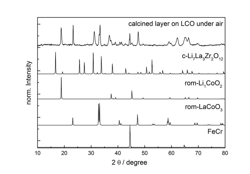
Abstract

Solid-state lithium batteries comprising a ceramic electrolyte instead of a liquid one enable safer high-
energy batteries. Their manufacturing usually requires a high temperature heat treatment to
interconnect electrolyte, electrodes, and if applicable, further components like current collectors.
Tantalum-substituted Li7La3Zr2O12 as electrolyte and LiCoO2 as active material on the cathode side
were chosen because of their high ionic conductivity and energy density, respectively. However, both
materials react severely with each other at temperatures around 1085 °C thus leading to detrimental
secondary phases.
Thin-film technologies open a pathway for manufacturing compounds of electrolyte and active
material at lower processing temperatures. Two of them are addressed in this work to manufacture thin
electrolyte layers of the aforementioned materials at low temperatures: physical vapor deposition and
coating technologies with liquid precursors. They are especially applicable for electrolyte layers since
electrolytes require a high density while at the same time their thickness can be as thin as possible,
provided that the separation of the electrodes is still guaranteed.

Keywords: solid-state batteries, Li7La3Zr2O12, ceramic processing, thin-film technology

                                                                                                       2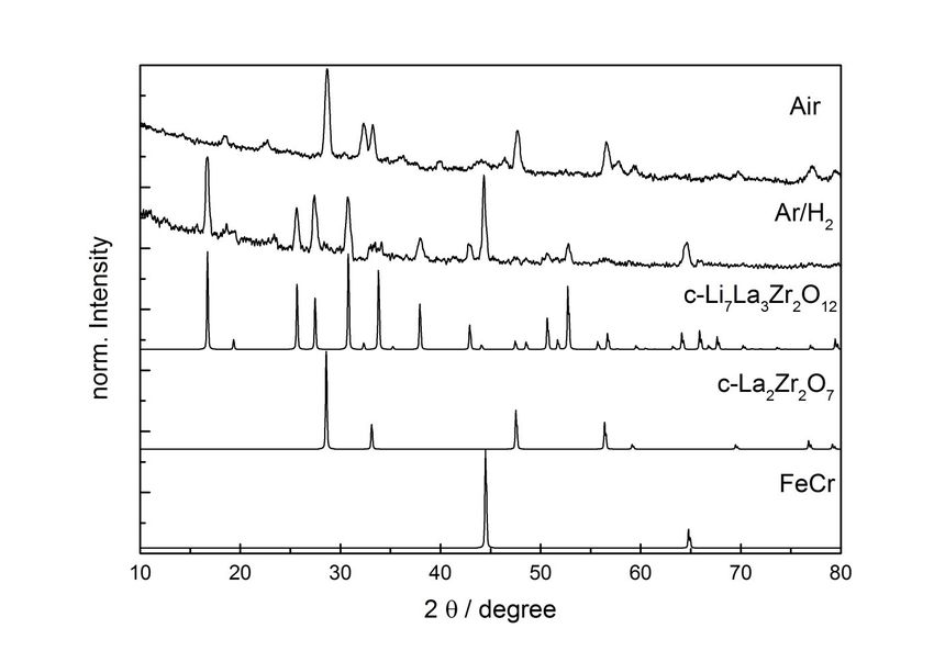
Introduction

Lithium ion batteries paved the way for the advances in portable electronic devices. They have
outstanding energy density and suitable charge-/discharge characteristics. They also have advantages
for large energy storage systems, for example for the challenges associated with a transition from a
fossil-based to a renewable energy supply. However, the requirements for large scale batteries are
different compared to batteries in portable electronics: battery safety, fast charge/ discharge capability
as well as cost and lifetime, for example, are important issues for electric vehicles and for stationary
electrical energy storage. These issues are partially linked to the use of liquid electrolyte in
conventional lithium ion batteries.
One strategy to circumvent those challenges is to replace today’s conventional liquid electrolytes
based on LiPF6 dissolved in organic solvent mixtures, like ethylene carbonate/ dimethyl carbonate, by
more stable compounds, like polymers or chemically different liquids, for example ionic liquids, or by
inorganic materials. The latter ones received much attention in recent years, also due to the discovery
of well performing inorganic lithium ion conductors [1]. They can be in a glassy state, partially
crystallized (“glass-ceramics”) or fully crystallized (polycrystalline/ceramic).
Among the inorganic lithium ion conductors, partially substituted Li7La3Zr2O12 (LLZ) is of particular
interest due to their high ionic conductivity. In this work a cubic garnet with a nominal composition
Li6,6La3Zr1.6Ta0.4O12 (LLZ:Ta) garnet was chosen as electrolyte material. Though this class of
materials does not have the highest lithium ion conductivity reported in the literature (~ 10-3 S/cm
compared to e.g. sulfur-based materials like Li2S-P2S5 mixtures or Li-Ge-P sulfides with ~ 10-2 S/cm
[2]), it offers the advantage of a high electrochemical stability window from 0 V versus Li +/Li0 to
more than 7 V [3]. Moreover, though it was found that LLZ reacts significantly with water [4], it can
in general be prepared and handled in air, since its reaction with moisture in time spans of hours for
processing appears not to adversely affect its performance [5].
In the case of already commercialized thin-film solid-state Li batteries, a glassy electrolyte, lithium
phosphorus oxynitride (partially N-substituted Li3PO4, also referred to as “LiPON”), is used. LiPON is
typically made by sputtering from a Li3PO4 target in nitrogen gas containing atmosphere. The sputter
conditions enable an exchange of oxygen ions by nitrogen ions[6,7]. Recent publications indicate that
also pure LiPON is not stable versus lithium metal; nevertheless, the reaction products are apparently
forming a stable Li ion conducting passivation layer and thus sustaining in principle the function of the
electrolyte [8]. However, due to the low ionic conductivity, ~ 10-6 S/cm of LiPON, LLZ:Ta is also
considered as an attractive material for thin-film batteries due to its higher ionic conductivity and
chemical stability [9].
LiCoO2 (LCO) was chosen as cathode material since it shows high electrochemical potential (4.2 V vs.
Li+/Li0). There are other cathode materials under development which provide even higher potentials,

                                                                                                        3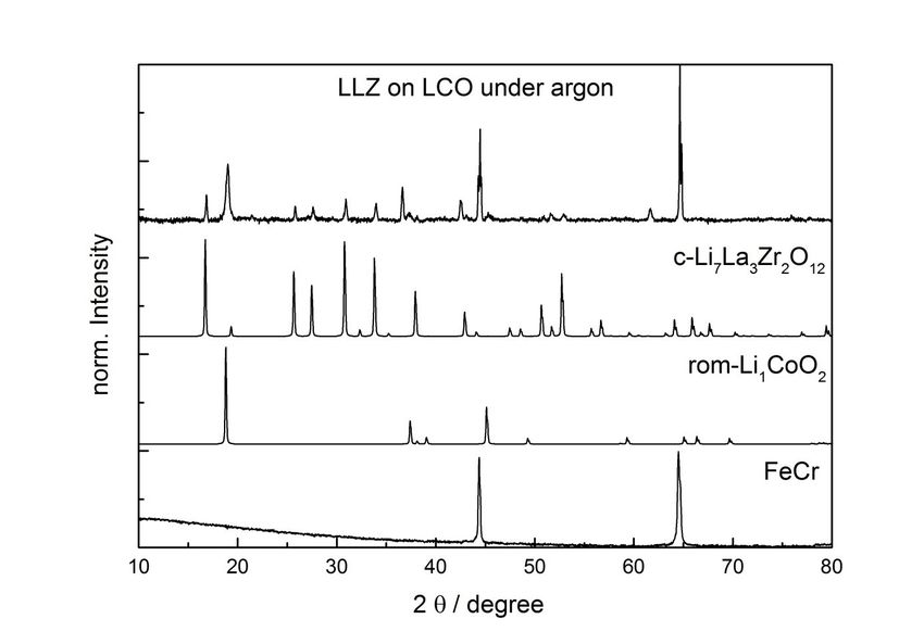
however, examples are described in literature where they react chemically even more severely with
LLZ-based garnet materials than LCO due to the additional transition metals [10,11,12].
In general, processing ceramics requires high temperature heat treatment for solidification and
densification. Chemical reactions between two compounds, each comprised of multiple metal cations,
are more likely at high temperatures and many of these reactions are known to lead to detrimental
secondary phases. The scope of this paper is to give a brief overview of two technologies for applying
thin electrolyte layers at lower processing temperatures than conventional ceramic processes such as
solid-state ceramic powders. Physical vapor deposition (PVD) and a wet-chemical technique based on
a liquid precursor and a subsequent ink-jet printing process are introduced.
The experiments of applying thin films by PVD and wet-chemical methods are performed on top of
inorganic substrates with thin-film current collectors and cathodes. Thin-film cathodes may only be
useful for applications that require low amounts of energy, bearing in mind that the energy content of a
battery cell correlates with the volume of electrodes (energy= voltage × specific capacity × density ×
volume). The purpose of thin films for all battery components, also cathodes, in this work is to analyze
the interaction of active storage material and the electrolyte in a simple geometry, with – in an ideal
case – well-defined planar interfaces and dense layer morphology, and analysis tools like Secondary
Ion Mass Spectrometry (SIMS) and Scanning Electron Microscopy (SEM) take considerable
advantage.

Experimental

Synthesis of the Li6.6La3Zr1.6Ta0.4O12 powder:
LLZ:Ta powder with the nominal composition Li6.6La3Zr1.6Ta0.4O12 was prepared by solid-state
reaction. The starting materials LiOH·H2O (Merck KGaA, Darmstadt, 98%), La2O3 (Merck KGaA,
Darmstadt, 99.9%), pre-dried at 900 °C for 10 h to remove water since La2O3 is known to be
hygroscopic, ZrO2 (Treibacher, 99.5%), and Ta2O5 (Inframat, 99.95%) were mixed in stoichiometric
amounts with ~20 mol-% Li in excess. An extra 2.5 mol-% of alpha-Al2O3 (Inframat, 99.9%) was
added into the powder as sintering additive [5]. A tungsten carbide crucible and pestle was used for
dry mixing the powder for one hour with a rotational speed of 100 rounds per minute. Then, the
powder was pressed into pellets for calcination at temperatures of 850 °C for one time and 1000 °C for
two times for 20 hours in each calcination step. Grinding and pressing were repeated between the
calcination steps. The final calcined powder was grinded into powder again for sintering process. The
composition of the powder after all calcination steps was determined by Inductively Coupled Plasma -
Optical Emission Spectroscopy (ICP-OES, ThermoScientific iCAP 6300). LCO powder was
purchased from MTI Corporation, Richmond USA, and used without alterations.

                                                                                                      4
For the chemical compatibility tests, the mixed powder was pressed into pellets by uniaxial pressing
using a die with 13 mm diameter, and a pressure of 150 MPa. For the high temperature treatment, the
pressed pellets were placed inside an alumina crucible and covered with an alumina lid. A ramp rate of
5 K/min was used for heating and free cooled to room temperature inside a furnace with 2 hours of
dwell time.
Care was taken to prevent the samples from any extensive air/ moisture exposure at room temperature
during handling and storage.
Characterization:
For the Differential Scanning Calorimetry (DSC) measurement and chemical compatibility tests,
LLZ:Ta and LCO powders were mixed in a volume ratio of 1:1 by an agate mortar and pestle. For
DSC measurement, a heating and cooling rate of 10 K/min was used for the measurement and a 30
minutes dwell time at 1200 °C.
The samples were characterized with regard to their phase purity by X-Ray Diffraction (XRD), with
-2 Bragg-Brentano geometry. For this purpose, a Bruker D4 Endeavor device using Cu-K radiation,
and a DIFFRACplus BASIC package released in 2009 was used.
Scanning Electron Microscopy (SEM) was conducted by a Zeiss Ultra 55 SEM (Carl Zeiss NTS
GmbH, Germany). Differential Scanning Calorimetry (DSC) measurements were done by a STA 449
F1 Jupiter differential scanning calorimeter from Netzsch, Germany.
Depth profiles of elemental distribution were measured by Time-of-Flight Secondary Ion Mass
Spectrometry (ToF-SIMS) with a ToF-SIMS IV instrument (IONTOF GmbH, Münster). Cs+ ions were
used as sputter ion with ion beam energy of 2 keV. The sputtered area was 300µm x 300µm. For
analysis Bi1+ ions with ion beam energy of 25 keV were used. The analyzed area was 80 x 80 µm2.
Thin film deposition by PVD:
Thin film depositions were carried out in a physical vapor deposition cluster system made by Von
Ardenne GmbH, Dresden, Germany. LCO and LLZ:Ta thin films were deposited via radio frequency
(RF) magnetron sputtering in a pure Ar plasma at 5x10⁻³ mbar pressure in the process chamber. The
sputter power for LLZ:Ta was 1.2 W/cm2, and a bias power of 0.1 W/cm2 was applied, while it was 1.0
W/cm2 and no bias power for LCO. Substrate deposition temperatures were 800 °C for LLZ:Ta, and
550 °C for LCO. The LCO target (purity 99.9 %) for sputter deposition was purchased from
EVOCHEM, Germany. The LLZ:Ta PVD target was made of LLZ:Ta powder as described in the
beginning of Experimental section of this paragraph, however without the addition of the sintering
additive Al2O3. The powder was slightly pressed onto a copper plate which served as target material
holder. Titanium as substrate was chosen because of its chemical compatibility to LCO, its high
electronic conductivity and sufficiently high melting point. Metals were chosen instead of ceramic
substrates because ceramics – especially oxide ceramics – often allow an uptake of lithium in their
5lattice. This issue is in general particularly critical for thin films. The heating was done in high
vacuum, and the probable superficial oxidation of titanium appeared to be without significant effect on
the results.
Thin film deposition by liquid precursors:
In this study, Li6.75La3Zr1.75Ta0.25O12 nano-particles prepared by microemulsion mediated synthesis are
used to form thin film electrolytes on Aluchrom YHf stainless steel foil (X8CrAl20-5; material code:
1.4767 according to DIN EN standard; supplier: VDM Metals GmbH, Werdohl, Germany). This
preparation method is based on a water-in-oil type microemulsion where the reverse water containing
micelles are used as nano-reactors to synthesize Li6.75La3Zr1.75Ta0.25O12 nano-particles [13,14]. After
addition of a stoichiometric amount of water contained in the microemulsion water-free clear stable
colloidal alcoholic solutions of suspended Li6.75La3Zr1.75Ta0.25O12 nano-particles on the primary
structure level was obtained. A lithium excess of 15 wt.-% was adjusted in the dispersion to
compensate lithium loss by diffusion in the substrate and evaporation as lithium containing species
during heat treatment for consolidating the printed Li6.75La3Zr1.75Ta0.25O12 green films.
For the synthesis of 100 g of the dispersion with a lithium excess of 15 wt.-% and a solid content of 5
wt.-%. 5.486 g dried lanthanum (III) acetate (Alfa Aesar, Karlsruhe, Germany) 4.738 g zirconium (IV)
propoxide (70 % in propanol, Alfa Aesar, Karlsruhe, Germany), 0.588 g tantalum (V) ethoxide and
0.320 g metallic lithium for the target composition Li6,75La3Zr1,75Ta0,25O12 were suspended in a mixture
of 150 ml methanol and propanol (1:1) under argon and stirred four hours under reflux until the
solution becomes clear. For hydrolysis of this moisture sensitive precursor solution 11.56 g of a
cationic microemulsion consisting of 3.74 wt.-% cethyl trimethyl ammonium bromide (Merck KGaA,
Darmstadt), 12.21 wt.-% pentan-1-ol (Alfa Aesar, Karlsruhe), 11.23 wt.-% distilled water and 72.82
wt.-% of cyclohexan (Merck KGaA, Darmstadt) were added dropwise. This leads directly to the
formation of a homogeneous optically transparent dispersion of LLZ:Ta nano-particles in the solvent.
6 g of propionic acid was added to the reaction mixture to prevent aging by agglomeration of the nano-
particles, which leads to a stabilization of the dispersion for periods up to one year. Finally, a part of
the solvent was evaporated until the solid content reaches 5 wt.-%. The typical particle size of the
mono-disperse LLZ:Ta nano-particles, determined by dynamic light scattering using a Malvern
Nanosizer (Malvern Instruments Ltd, Enigma Business Park, Worchestershire, UK), is estimated to be
4 nm. The stable nano-particle dispersion prepared in this way was used directly for the preparation of
the LLZ:Ta ink.
A part of the solvent was replaced by an alcohol with reduced vapor pressure by evaporating the
solvent mixture of the original dispersion and refill the system with pentan-1-ol in order to avoid
undesired spreading of the spraying drops on the sample surface and blocking of the nozzles. A
substitution of 20 wt.-% was found to be the optimum to ensure stable processing conditions during
6inkjet printing. The final ink was filtered using a 0.2 µm polymer filter (Whatman, FP 30/0.2 CA) to
clean the inks from dust and particle agglomerates and filled in the ink container of the printer.
A commercial inkjet printer (PixDro LP50, Meyer Burger Technology AG, Eindhoven, The
Netherlands) was used to coat thin LLZ:Ta films on Aluchrom YHf. The inkjet printer was operated in
a conventional laboratory under ambient conditions. A more detailed description of the printer set-up
can be found elsewhere [15,16]. The device was equipped with a commercial industrial print head
(Spectra 128SE from Fujifilm Dimatix Inc., Santa Clara, CA, USA, delivered along with PixDro). The
diameter of the nozzles of 35 µm allows printing suspensions with particle sizes up to 1 µm with a
resolution up to 900 dpi. Pulsed voltage with frequencies up to 10 kHz enabled the generation of high
frequency pressure waves leading to the formation of ink drops with well-defined volume of around
30 pl and to the adjustment of the spraying intensity.
Stable and reliable operating conditions with the current printing set-up were achieved when the
voltage was set to 120 V at a frequency of 100 Hz and duration of the voltage pulses of 8 µs at
ambient temperature. All printings were carried out with a maximum print speed of 400 mm/s. To
increase the resolution and the acutance of the printing the print head angle was set to 80 ° relating to
the printing direction and a quality factor of 4 was used. This quality factor was an internal software
parameter to influence the printing strategy by activation of different numbers of nozzles to print one
pixel line in print direction. In our study 4 nozzles are used, resulting in a breakdown of the printing
process in 4 coating steps. First, a coarse raster was printed on the substrate, followed by successive
filling of the gaps between the printed dots in the subsequent printing steps to complete the coating
process. This printing strategy results in a homogenous layer with high acutance. Table 1 summarizes
the operation range of the Spectra 128 SE printing head as well as the optimized printing parameters
consistently used for this study. For all other changeable operating parameters the pre-adjusted default
values are used. Aluchrom YHf sheets with dimensions of 2.5 cm×2.5 cm and a thickness of 80 µm
were used as first substrates for the LLZ:Ta layers due to their excellent oxidation stability at
temperatures up to 1100 °C [17]. Lithium cobalt oxide was deposited on Aluchrom YHf steel foil by
radio frequency magnetron sputtering as a second type of substrate.
Table 1: Range of operation parameters of the Spectra 128SE printing head and optimized printing
parameters used for this study.
Optimized Parameter
Operation range of the
Parameter for printing the
Spectra SE 128 print head
LLZ:Ta dispersion
Print head voltage 0 - 130 V 120 V
Duration of voltage pulse 0 - 10 µs 8 µs
Frequency of voltage pulse 0 - 10 kHz 100 Hz
7Print speed 50 - 400 mm/s 400 mm/s
Print head angle 0 - 90 ° 80 °
Quality factor 1-8 4
The printer was programmed to print a square area of 20 x 20 mm2 centred to the sample. The
resulting wet films were dried for one hour at 120 °C followed by a subsequent calcination and
sintering under synthetic air, argon or under 2 vol.-% hydrogen in argon. In the present study the
reactor for sintering of the green LLZ:Ta layers under adjustable atmosphere consists of a “heating
zone” and a “cooling zone”. The heating zone for sintering at elevated temperatures (typically 700 –
1000 °C) inside a tube furnace and the cooling zone for quenching the sintered specimen to room
temperature outside the furnace are enclosed in a gastight quartz tube. For sintering a pre-heated
furnace at desired temperature was used, where the LLZ:Ta films are consolidated under a continuous
gas flow of 10 l/h of synthetic air, argon or hydrogen in argon. In order to investigate the time
dependent sintering behavior (five minutes to one hour) the sample was placed on a specimen holder,
equipped with a thermocouple for monitoring the sample temperature and fixed on a driving rod for a
quick change between both zones. In order to control the oxygen partial pressure of the reactor
atmosphere during the sintering process the gas outlet system was equipped with lambda sensor (Zirox
Sensor GmbH, Greifswald, Germany).
The specimens were settled on the sample holder at the end of the connecting rod for sintering, and the
reactor closed in a gas-tight manner. After purging the reactor with synthetic air or hydrogen/ argon
mixture to remove the residual moist air, the samples were quickly slid into the heating zone. After
stabilization of the specimen temperature and a certain sintering time the heat treatment was stopped
by sliding the sample with the driving rod from the heating zone into the cooling zone. Finally the
sintered specimens were taken out after cooling below 100 °C and stored under argon.
Results and discussion
Phase stability and compatibility between Li6.6La3Zr1.6Ta0.4O12 and LiCoO2:
Figure 1 shows the result of DSC measurements for the mixture of LLZ:Ta and LCO from room
temperature to 1200 °C. A small peak was observed at 700 °C which implies LLZ:Ta and LCO may
have a reaction under this heat treatment conditions. This is in agreement with Ren’s report [10] that
LLZ:Ta and LCO could react to form LaCoO3 at temperatures higher than 700 °C. However, the
byproduct from this reaction was not observable from their XRD result even for the sample with 10
hours dwell time at 900 °C [10]. The DSC curve in figure 1 is later dominated by one big peak at 1085
°C that it attributed to an irreversible reaction, since on the cooling curve only a minor signal was
detected (not shown in Fig. 1 because of clarity reasons) . Apparently the reaction at 700 °C is
sluggish, and the mixture appeared to be mainly stable in the temperature range from room
8temperature to 1085 °C. This is corroborated by an XRD measurement of a mixture of the two
powders which were heat treated to 1050 °C and 1100°C, respectively, and subsequently analyzed
(figure 2). At 1050 °C, all peaks can be clearly attributed to the original constituents LCO and cubic
garnet LLZ (one effect of Ta substitution in LLZ is the stabilization of the cubic phase of the garnet to
lower temperature) as in the as-mixed LLZ:Ta/LCO powder. The LLZ:Ta powder has slight shifts of
the peak position compared to the reference pattern, which is attributed to the slightly different
composition of LLZ:Ta compared to the reference pattern. The shoulders in the XRD pattern are also
found in the as-mixed powders. The broad bump at low angles is attributed to fluorescence of Co in
LCO. No secondary phase was detectable by XRD after heat treated at 1050 °C which means the
reaction at 700 °C seems to be minor. [18] reports a slight decomposition reaction of pure LCO with
temperature, and [19] corroborates that there is a reaction between LLZ and LCO along with an
interdiffusion in the temperature range to 1150 °C.
However, at 1100°C the XRD patterns significantly differ from the original mixtures. The result
indicates a severe chemical reaction happened at this temperature which destroys both of the materials.
The pronounced double peak around 32 degrees 2 can be well interpreted as originating from the
presence of LaCoO3,(PC-PDF database: # 01-073-5972) in the heat-treated mixture. More phases, for
example LiCoO3 (#01-076-7878), Li2CoZrO4 (# 00-040-0367), or Li3Zr0.18Ta0.82O4 (#00-042-0045),
would also match to describe the diffraction pattern. However, there are too many peaks present to
make an unambiguous identification of all phases.
Kim et al. [20] found a reaction of LCO and pure LLZ (without any arbitrary substitution like e.g. Ta)
and Ren et al. [10] between LCO and LLZ:Ta at lower temperatures, namely at around 700 °C.
Therefore, the Ta substitution or the different crystal structure (tetragonal vs cubic) apparently do not
affect the stability. In [10], it is stated that LCO and LLZ:Ta start reacting with each other at 700 °C,
confirmed by Raman measurements, however, it has not been revealed by XRD: according to XRD
measurements the material combination seems to be stable until few hundreds degrees higher
temperature for a few hours. This might be related to the amount or spatial distribution of the reaction
products. Raman measurements also revealed the formation of LaCoO3 after high temperature
treatment [10].
Physical vapor deposition:
The XRD-pattern and the surface of a sputtered LLZ:Ta layer on LCO is presented in figure 3. The
substrate temperature during deposition was 800 °C. As shown in [9], high substrate temperature is in
general necessary to create the cubic garnet LLZ phase which is competing with the insulating
La2Zr2O7 pyrochlore structure, though high temperature might easily be regarded as counter-intuitive
when depositing a compound with comparatively volatile Li species.
9While the phase composition (figure 3, left) matches well to the desired set-up, the morphology is no
more completely flat (figure 3, right), although PVD in general is assumed to be a conformal
deposition process. The surface exhibits a wavy morphology and some interfaces between apparently
perfectly dense islands. No spallation of the LLZ:Ta PVD layer occurred. The exact reasons for the
island structure are up to now unclear. Part of the junctions might be attributed to an island growth
mechanism, which is typical during PVD, when the substrate temperature is significantly lower than
the melting point of the deposited material [21]. Some interfaces may be interpreted as cracks due to
mechanical stresses, for example during cooling the sample after deposition: the cubic garnet LLZ
structure has a thermal expansion coefficient of around 16·10-6 1/K [22], in accordance with own
measurements (not shown), LCO around 13·10-6 1/K [22], while the Ti substrate has ca. 8.5·10-6 1/K
[23], thus leading to tensile stresses in the PVD layer during cooling. The LCO layer and the Ti
substrate are apparently not visible through the cracks of the LLZ:Ta layer.
The analysis by SIMS revealed inhomogeneities along the thin-film growth direction in the half cell
(figure 4), although the XRD confirmed the desired phases. The signals of lithium species are
comparatively constant with time in the beginning of the measurement (t=0 s) and thus with layer
depth, while the signals accounting for La and Zr start from very low values and significantly increase
during the first 1500 s. Even a somehow buckled surface can hardly explain the differences in the
ithium, Zr and La species signal, respectively. Thus it has to be concluded that a lithium rich surface
layer was formed during processing. PVD is a high vacuum technique, and the base pressures allow
the conclusion that only traces of water might be present during the sputter process. Furthermore, there
is no sharp interface between LLZ:Ta and LCO the smoothly sloped signals of Co, La and Zr species
support the assumption of considerable interdiffusion from the cathode into the electrolyte and vice
versa.
Moreover, the Ti+ signal appeared already after having removed about one quarter of the electrolyte
thickness from the surface side. This may either explained by Ti diffusion from the substrate into the
cathode and even into the electrolyte, or as an artefact due to some cracks in the layer(s). Since an area
of 80µm x 80µm was analyzed and SEM analysis verified only slim cracks and very small areas
without PVD layer(s), the latter assumption is regarded as less likely. Ganesan et al. reported that Ti
can be incorporated into LCO [24] – an observation also known from other cathode active materials
for lithium batteries [25], where the problem was solved by changing the current collector from metals
to intermetallic compounds.
Liquid precursor deposition:
First, samples of dried LLZ:Ta nano-particle powder were calcined under synthetic air at 700, 800 and
900 °C respectively, and the phase formation was measured by XRD in order to investigate a suitable
crystallisation temperature to achieve phase pure LLZ:Ta layers. Therefore, the solvent of the LLZ:Ta
10dispersion was completely evaporated and the resulting white powder vacuum dried at 120 °C
overnight. The samples were heated up in an alumina crucible to the target temperatures with a heating
rate of 3 K/min and calcined for one hour. Figure 5 shows the obtained XRD patterns, indicating that
at 800 °C only the cubic phase of LLZ:Ta was detected. At 700 and 900 °C the calcined powder
contained impurities of La2Zr2O7 and hexagonal La2O3. Accordingly a sintering temperature of 800 °C
was further used for the heat treatment of the LLZ:Ta layers.
For the consolidation of the LLZ:Ta thin films, samples were calcined at 800 °C in the pre-heated
reactor under synthetic air for 10, 20, 30, 40, 50 and 60 minutes, respectively. It was found that a
dwell time of 10 minutes was necessary to complete the phase formation. Figure 6 displays the XRD
patterns of the final transparent layer on the Aluchrom YHf substrate at this dwell time: In the case of
air atmosphere solely lanthanum zirconate was detected. This result indicates that during sintering a
virtually complete lithium loss occurred by either diffusion into the substrate, or – more specific, into
the oxide scale of the heat-treated metal – or by an evaporation of lithium-containing species, or both
mechanisms. A sample was annealed 10 minutes at 800 °C under a mixture of 2 % hydrogen in argon
to minimize the oxidation of the stainless steel substrate in order to prove the thesis that the oxide
scale takes up the lithium. As a result of the heat treatment in argon, a phase pure LLZ:Ta layer was
obtained (figure 6).
SEM images of the surface and of the cross section are shown in figure 7. A porous electrolyte layer
with a thickness of approximately 400 nm with a rough surface was obtained, indicating that the inkjet
coating process, the composition of the ink and the thermal treatment need to be further optimized.
The LLZ:Ta layer was tightly bonded on a thin 60 nm aluminum oxide film as an oxidation layer on
the surface of the metallic substrate below. The formation of this layer was caused by the oxidation of
metallic aluminum as a part of the Aluchrom YHf substrate by residual oxygen in the reactor
atmosphere. As a conclusion of this result the lithium excess in the LLZ:Ta ink of 15 wt.-% was high
enough to compensate the alkali metal loss during processing to complete the desired phase formation
of cubic LLZ.
In an additional experiment the LLZ:Ta dispersion was inkjet printed on a lithium cobalt oxide surface
as a cathode material with a saturated lithium content to minimize the alkali metal loss during sintering
and to directly built up a half cell. Nevertheless, it has to be taken into account that also LCO may lose
lithium to the substrate during processing accompanied with a heat treatment. Thin LCO layers
sputtered on the Aluchrom YHf foil were used as a substrate for coating the electrolyte layer, followed
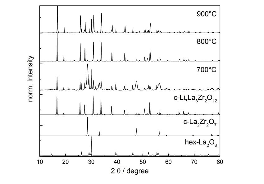
by a subsequent annealing for 10 minutes at 800 °C under synthetic air. Figure 8 shows the XRD
pattern of the calcined sample where besides some reflexes of the metal substrate only rhombohedral
lithium cobalt oxide and lanthanum cobalt oxide were identified. This result indicates that during the
heat treatment a massive La loss occurred by diffusion from the printed electrolyte layer into the LCO
11substrate and suppressed the formation of an LLZ film. A thermodynamically stable LaCoO3
secondary phase formed under these sintering conditions. Hence, the application of highly sinteractive
LLZ nano-particles to generate thin electrolyte layers at low sintering temperatures was accompanied
with the high mobility of the metal ions during calcination which enhanced interdiffusion. As a
consequence, the formation of lanthanum cobalt oxide already occurred at 800 °C in contrast to the
result for the powder mixture of LLZ:Ta and LCO where this perovskite phase can only be observed at
annealing temperatures above around 1085 °C.
Figure 9 shows the XRD-results for samples heat-treated in argon instead of air. Here, the XRD
pattern contains clear peaks of the substrate, of LCO and of cubic LLZ. Nevertheless, there are still a
few peaks which could not be unambiguosly identified. A hydrogen/argon atmosphere could not be
applied as used in the previous experiments with pure Aluchrom YHf as substrate since LCO would
have decomposed at such low oxygen partial pressures [26].
Overall discussion:
State-of-the-art lithium ion batteries with liquid electrolyte are known to be already beyond their
materials (electro-)chemical stability windows; this is the reason for partial decomposition products at
the interface area of the electrodes and the liquid electrolyte (like the solid-electrolyte interphase, or
SEI). One assumption in the beginning of the research on inorganic batteries with solid-state
electrolyte was a more stable interface thus leading to less reaction products and less lithium loss. This
work, however, shows that there are significant reactions between LLZ:Ta and LCO, and also other
higher voltage active materials (cathodes) during processing at high temperature [10,11,12] which
complicates the set-up of entire battery cells just by mixing and heat-treatment. The decomposition
starts considerably below the temperatures and times needed for a conventional solidification by
sintering processes. Therefore, it is difficult or even not possible to build batteries in this way in order
to assess their full performance.
The kinetics of the reactions are apparently a key to combine LLZ solid electrolyte with high-
performing electrodes like LCO. In the paragraph “Phase stability and compatibility between
Li6.6La3Zr1.6Ta0.4O12 and LiCoO2” it has been shown that first reactions obviously start at around 700
°C, in accordance to the literature, but seem to be sluggish. A severe decomposition occurs above
1050 °C for particle mixtures. Processing at lower temperatures, but nevertheless applying enough
energy for proper crystallization of electrolyte and electrodes and creating a tight bonding between
them, is necessary in order to have a chance to electrochemically characterize this type of battery
(half) cells. Here PVD and liquid precursors come into play.
12Sputtering as one PVD process, which is presented in this work, adds intrinsically a sort of kinetic
energy to the species in the gas phase during deposition, allowing crystallization and adhesion at lower
substrate temperatures. Thus cubic LLZ:Ta could be successfully applied on LCO. However,
inhomogeneities and interdiffusion occurred which has to be solved prior to a characterization of the
compound.
Interdiffusion plays an important role also in the case of liquid precursors. The precursors are highly
reactive in their initial state, which allow low processing temperatures, but they are also more affected
by the thermodynamic stability of competing phases for the same reason.
For both, PVD and liquid precursors, the choice of substrate is essential for the final result. In general,
ceramic substrates are prone to a huge uptake of lithium during processing and cannot be used, since
too low amounts of lithium are present in the thin functional layers to form the correct phases with
appropriate stoichiometry. Therefore, the metal substrates in this work were chosen with regard to an
as low alloying speed with Li as possible. The metals of the periodic table that do not alloy with
lithium in general grow an oxide scale during heat treatment, which is again a sink for lithium. This
explains why depositions in reaction atmospheres with different oxygen partial pressure lead to
considerably different results: Atmospheres with lower oxygen partial pressure lead to lower oxide
scale growth and thus to fewer amounts of potential lithium sinks.
The results also indicate that suitable ceramic electrode/electrolyte combinations are limited without
the implementation of intermediate layers between electrodes and electrolyte: this concept of interface
engineering was for example introduced by [27,28]. Either material combinations have to be taken
which allow a processing at lower temperatures and short processing times, or material combinations
which do not react with each other (but are probably hard to find), or interlayers to prevent
interdiffusion have to be applied.
Conclusions:
The thermodynamic phase instability of mixtures of LiCoO2 (LCO)-based materials and partially Ta-
substituted Li7La3Zr2O12 (LLZ:Ta) electrolyte materials impedes the combined processing via
conventional ceramic techniques. The examples in this paper, (i) physical vapor deposition (PVD) and
(ii) liquid precursor based materials and subsequent fast thermal processing, demonstrate how a
combination of LCO and LLZ:Ta can be obtained by processing at lower temperature thus
circumventing the thermodynamic stability limits, but at the same time give rise to new challenges.
For both techniques it was found that interdiffusion of the mobile elements significantly affects the
phase generation and stoichiometric composition of the functional layers, also due to the low layer
13thickness range of few micrometers or even lower, leading to a low volume-to-surface ratio. LLZ:Ta
layers made by PVD at temperatures as high as 800 °C form the right phase and suppress the
competing La2Zr2O7 pyrochlore phase. Inhomogeneities may arise either due to the process which is
based on sputter-yields or due to interdiffusion with time. For liquid precursors, a LaCoO3 perovskite
phase was identified as a main competitive phase when applying the LLZ:Ta precursor on LiCoO2
cathode layers. The choice of suitable reactor atmospheres during consolidation of ceramic battery
materials was necessary to prevent oxidation of the metallic substrates. These undesired additional
oxides can interact at higher temperatures with the functional layers by interdiffusion of metallic ions,
including also lithium diffusion from the electrodes and electrolyte, respectively, to the substrate oxide
layer. As a consequence, changes in the stoichiometry and in the phase compositions of the battery cell
components are possible.
References:
[1] V. Thangadurai, S. Narayanan and D. Pinzaru, Royal Society of Chemistry (2014), doi:
10.1039/c4cs00020j
[2] N. Kamaya, Y. Yamakawa, M. Hirayama, R. Kanno, M. Yonemura, T. Kamiyama, Y. Kato,
S. Hama, K. Kawamoto, A. Mitsui, Nature Mat., 10, 682 (2011)
[3] C.-L. Tsai, E. Dashjav, E.-M. Hammer, M. Finsterbusch, F. Tietz, S. Uhlenbruck, H.P.
Buchkremer, Journal of Electroceramics 35, 25 (2015)
[4] C.-W. Ahn, J.-J. Choi, J. Ryu, B.-D. Hahn, J.-W. Kim, W.-H. Yoon, J.-H. Choi, J.-S. Lee, D.-
S. Park, Journal of Power Sources 272, 554 (2014)
[5] C.-L. Tsai, V. Roddatis, C. Vinod Chandran, Q. Ma, S. Uhlenbruck, M. Bram, P. Heitjans, O.
Guillon, ACS Appl. Mater. Interfaces 8 (16), 10617 (2016)
[6] X. Yu, J.B. Bates, G.E. Jellison, Jr., F.X. Hart, J. Electrochem Soc. 144, 524 (1997)
7] J. Li, C. Ma, M. Chi, C. Liang, and N.J. Dudney, Adv. Energy Mater. 5, 1401408 (1-6) (2015)
[8] A. Schwöbel, R. Hausbrand, W. Jaegermann, Solid State Ionics 273, 51 (2015)
[9] S. Lobe, C. Dellen, M. Finsterbusch, H.-G. Gehrke, D. Sebold, C.-L. Tsai, S. Uhlenbruck, O.
Guillon, Journal of Power Sources 307 684 (2016)
[10] Y. Ren, T. Liu, Y. Shen, Y. Lin, C. Nan; J. Materiomics (2016)
doi.org/10.1016/j.jmat.2016.04.003
14[11] V. Thangadurai, W. Weppner, Journal of Power Sources 142 339 (2005)
[12] L. Miara, A. Windmüller, C.-L. Tsai, W. D. Richards, Q. Ma, S. Uhlenbruck, O. Guillon, G.
Ceder, ACS Appl. Mater. Interfaces 8, 26842 (2016)
[13] C. Pithan, T. Schneller, Y. Shiratori, S. B. Majumder, F. H. Haegel, J. Dornseiffer, R. Waser,
Int. J. Mater. Res. 97, 499 (2006)
[14] C. Beck, W. Härtl, R. Hempelmann, J. Mater. Res. 13, 3147 (1998)
[15] PixDro B.V., Documentation PixDro LP50 Inkjet Printer, A-000-00-195, Eindhoven (NL),
2008.
[16] M. Bram, J. Dornseiffer, J. Hoffmann, T. Van Gestel, W. Meulenberg, D. Stöver, J. Am.
Ceram. Soc. 98, 2388 (2015)
[17] H. Echsler, H. Hattendorf, L. Singheiser, W. J. Quadakkers, Materials and Corrosion 57, 115
(2006)
[18] E. Antolini, M. Ferretti, Journal of Solid State Chemistry 117, 1 (1995)
[19] K. Park, B.-C. Yu, J.-W. Jung, Y. Li, W. Zhou, H. Gao, S. Son, and J. B. Goodenough,
Chem.Mater. 28, 8051 (2016)
[20] K.H. Kim, Y. Iriyama, K. Yamamoto, S. Kumazaki, T. Asaka, K. Tanabe, C.A.J. Fisher, T.
Hirayama, R. Murugan, Z. Ogumi, Journal of Power Sources 196, 764 (2011)
[21] P. Grütter and U.T. Dürig, Phys Rev B 49, 2021 (1994)
[22] A.A. Hubaud, D.J. Schroeder, B.J. Ingram, J.S. Okasinski, J.T. Vaughey, J. Alloys
Compounds, 804 (2015)
[23] D. Low, T. Sumii and M. Swain, Journal of Oral Rehabilitation 28, 239 (2011)
[24] M. Ganesan, S. Sundararajan, M.V.T. Dhananjeyan, K.B. Sarangapani, N.G. Renganathan,
Materials Science and Engineering B 131, 203 (2006)
[25] A. Bünting, S. Uhlenbruck, C. Dellen, M. Finsterbusch, C.-L. Tsai, D. Sebold,
H.P. Buchkremer, R. Vaßen, Journal of Power Sources 281, 326 (2015)
[26] S.-T. Myung, K. Amine, Y.-K. Sun, Journal of Power Sources 283, 219 (2015)
15[27] T. Kato, T. Hamanaka, K. Yamamoto, T. Hirayama, F. Sagane, M. Motoyama, Y. Iriyama,
Journal of Power Sources 260, 292 (2014)
[28] Zhi-Jia Zhang, Shu-Lei Chou, Qin-Fen Gu, Hua-Kun Liu, Hui-Jun Li, Ozawa, Jia-Zhao Wang,
ACS Appl. Mater. Interfaces 6, 22155 (2014)
16Figure captions:
Fig. 1 Differential Scanning Calorimetry (DSC) of a mixture of LLZ:Ta and LCO. The continuous
line corresponds to the measurement from room temperature to 1200 °C, the dotted line to the
cooling curve
Fig. 2 XRD patterns of as mixed LLZ:Ta/LCO powder and powders that were heat treated at 1050 °C
and 1100 °C, respectively. The measurements were performed at room temperature, after
cooling of the samples. The closed diamonds mark the diffraction peaks of LCO, open
diamonds correspond to those of cubic garnet LLZ. The height of the symbols illustrates a trend
of the relative peaks intensities of the corresponding compound (powder); data taken of the
ICSD database (LCO: #48103; LLZ: #183686)
Fig. 3 Left: XRD of a sputtered LLZ:Ta layer on sputtered LCO and titanium metal as substrate. Small
amounts of the secondary phase La2Zr2O7 (pyrochlore) are present. Right: SEM image of the
surface of LLZ:Ta (secondary electron image, 15 kV acceleration voltage)
Fig. 4 SIMS depth profiles of charged species of the compound comprising an LLZ:Ta top layer, an
LCO layer and the Ti substrate. Constant intensity of an ion can be interpreted as an indication
for constant element concentration in the film growth direction (as long as different sputter
yields and matrix effects can be neglected), steep changes in the intensity as an indication for a
sharp interface, while smooth slopes are guessed to show interdiffusion. The arrows in top of
the graph may act as a guide to the eyes to assess the regions of LLZ:Ta and LCO, respectively
Fig. 5 XRD patterns of the LLZ:Ta powder samples calcined in air at 700, 800 and 900 °C
Fig. 6 XRD patterns of the consolidated LLZ:Ta films on the Aluchrom YHf substrate calcined 10
min at 800 °C in synthetic air and in hydrogen/argon atmosphere, respectively. FeCr denotes the
reference pattern of the substrate alloy Aluchrom YHf
Fig. 7 SEM images of the surface (left) and in cross section of the LLZ:Ta layer calcined under
hydrogen/argon atmosphere on the Aluchrom YHf substrate
17Fig. 8 XRD patterns of the consolidated LLZ:Ta film calcined 10 min at 800 °C under synthetic air, on
a sputtered LCO thin film with underlying Aluchrom YHf substrate
Fig. 9 XRD patterns of the consolidated LLZ:Ta film calcined 10 min at 800 °C under argon, on a
sputtered LCO thin film with underlying Aluchrom YHf substrate
18Fig. 1
6
LCO/ LLZ:Ta T=1085 °C
mixture
5
DSC signal / W/g
4
3
2
1
0
0 200 400 600 800 1000 1200
Temperature / °C
19Fig. 2
LCO
cubic garnet LLZ
1100 °C
1050 °C
as-mixed
10 20 30 40 50 60 70 80
2 / degree
20Fig. 3
LLTZ/ LCO on Ti; 800°C
Li7La3Zr2O12, cub.
12000
LiCoO2, hex.
Ti, hex.
La2Zr2O7, cub.
Intensity (cts)
8000
4000
10 m
0
10 20 30 40 50 60
2 / degree
21Fig. 4
LLTZ LCO
105 Li+
blurred
6 + interface
10 4
Li
Intensity / counts
103 LaO+
Ti+
+
102 ZrO CsCo+
O+
1
10
Co+
100
0 1000 2000 3000 4000 5000
delay for Sputter Time / s
ZrO+, LaO+
22Fig. 5
23Fig. 6
24Fig. 7
25Fig. 8
26Fig. 9
27You can also read