Cold atom interferometry sensors: physics and technologies - JRC Publications Repository
←
→
Page content transcription
If your browser does not render page correctly, please read the page content below
Cold atom interferometry sensors:
physics and technologies

 A scientific background
 for EU policymaking

 Travagnin, M.

 2020

 EUR 30289 EN
This publication is a Technical report by the Joint Research Centre (JRC), the European Commission’s science
and knowledge service. It aims to provide evidence-based scientific support to the European policymaking
process. The scientific output expressed does not imply a policy position of the European Commission. Neither
the European Commission nor any person acting on behalf of the Commission is responsible for the use that
might be made of this publication.

Contact information
Name: Martino Travagnin
Email: Martino.Travagnin@ec.europa.eu

EU Science Hub
https://ec.europa.eu/jrc

JRC121223

EUR 30289 EN

 PDF ISBN 978-92-76-20405-3 ISSN 1831-9424 doi:10.2760/315209

Luxembourg: Publications Office of the European Union, 2020

© European Union, 2020

The reuse policy of the European Commission is implemented by Commission Decision 2011/833/EU of 12
December 2011 on the reuse of Commission documents (OJ L 330, 14.12.2011, p. 39). Reuse is authorised,
provided the source of the document is acknowledged and its original meaning or message is not distorted. The
European Commission shall not be liable for any consequence stemming from the reuse. For any use or
reproduction of photos or other material that is not owned by the EU, permission must be sought directly from
the copyright holders.

All content © European Union, 2020

How to cite this report:

M. Travagnin, Cold atom interferometry sensors: physics and technologies. A scientific background for EU
policymaking, 2020, EUR 30289 EN, Publications Office of the European Union, Luxembourg, 2020, ISBN 978-
92-76-20405-3, doi:10.2760/315209, JRC121223

Contents

Acknowledgements ................................................................................................ 1
Abstract ............................................................................................................... 2
1 Introduction ...................................................................................................... 3
2 Underlying physics ............................................................................................. 6
3 Research highlights .......................................................................................... 14
 3.1 Gyroscopes and accelerometers ................................................................... 14
 3.2 Gravimeters and gravity gradiometers .......................................................... 25
4 Worldwide players ........................................................................................... 36
5 Conclusions .................................................................................................... 39
References ......................................................................................................... 40
List of abbreviations and definitions ....................................................................... 42

 i
Acknowledgements
This work has been done in the framework of the SynQArc administrative arrangement
between DG JRC and DG DEFIS. I am glad to acknowledge continuous help from my JRC
colleague Adam Lewis, and useful conversations with several DG DEFIS colleagues.

 1
Abstract
This report describes the physical principles underpinning cold atom interferometry (CAI)
and shows how they can be leveraged to develop high-performance inertial and gravity
sensors; the distinguishing properties and the maturity level of such sensors will also be
assessed.
Proof-of-principles demonstrations have been made for CAI-based accelerometers and
gyroscopes, which can enable long-term autonomous navigation and precise positioning
for ships, submarines, and satellites. CAI-based gravimeters and gravity gradiometers
have been developed and are being tested on the ground; satellite-based systems could
in the future be used to monitor the Earth gravity field. This would allow a better
understanding of several geophysical and climate phenomena which require long-term
policies solidly supported by data.
Quantum sensors based on cold atom interferometry may therefore impact existing and
future EU programmes on space, defence, and Earth observation. This report provides
background knowledge of the field to a non-specialist audience, and in particular to EU
policymakers involved in technology support and potential applications.

 2
1 Introduction
It is well-known that the quantum properties of atoms can be exploited for a number of
important applications, such as measuring time and frequency, storing and processing
information, and sensing. Since their implementation typically requires the atoms to
interact with one or more laser beams, the atoms must remain confined in a region of
space where they can be shone upon by the beams in charge of quantum state
initialization, manipulation, and interrogation. In sensors, the manipulation step
corresponds to the interaction with the operator representing the quantity to be
measured. Since the atoms must remain in the laser beam paths all the time necessary
for the required interactions to take place, the need to reduce their thermal motion
arises.
An atom can therefore be considered to be “cold” when its thermal velocity has been
reduced to such an extent that it becomes possible to interact with it in a manner that
makes its quantum properties accessible and exploitable. In more technical terms, the
atomic wavefunction which represents the probability density must remain confined for a
long enough time in the volume where the required light-matter interactions take place.
This aim is usually accomplished by combining the trapping potential generated by a
magnetic field with three pairs of suitably crafted counter-propagating laser beams,
which repeatedly interact with the atom in such a way to progressively reduce its
momentum. The whole device goes under the name of magneto-optical trap (MOT).
Laser systems therefore play a fundamental role in cold atom physics, since they first
cool the atom and then they interact with it by sequentially changing its quantum state
according to the requirements of the targeted application. The atoms emerging from a
MOT have typical temperatures in the micro-Kelvin (1µ°K = 10-6 Kelvin) range. Each of
them then undergoes a sequence of interactions with the laser beams orchestrating the
application, which ends with a measurement of the final quantum state. Since each atom
behaves independently from the others, the total system response will be given by an
incoherent superposition of signals. The shot noise amplitude affecting the system will
therefore decrease as 1/N1/2, N being the number of atoms which undergo all the
required interaction steps.
There exists however a completely different state of matter, called a Bose-Einstein
condensate (BEC), for which atoms must be cooled down to the nano-Kelvin (1n°K =
10-9 Kelvin) range. Under suitably controlled conditions, at these ultra-cold temperatures
the atoms cannot be described by independent wavefunctions: the whole atomic system
coalesces in a sort of macroscopic quantum state which is described by a unique
wavefunction. To reach the temperatures necessary for the atoms to condense in the
Bose-Einstein state a MOT does not suffice, and after having emerged from it the atoms
must undergo further cooling processes. Since a BEC is described by a single
wavefunction, all of its atoms behave coherently: the overall system response will thus
not be affected by shot noise. This constitutes a very interesting feature, in particular for
applications requiring very high sensitivity levels. Generally speaking, BECs have not yet
reached the technological maturity required for field applications: most of the research is
still focused on understanding the properties of the condensate itself, and identifying the
main factors which cause the observed experimental deviations in the phenomenon from
the theoretical predictions. It must however be acknowledged that the last ~20 years
have seen a remarkable interest in the use of BECs for scientific experiments aimed at
tests of fundamental physical theories.
The history of the technical developments which enabled the trapping of atoms and the
interaction with atomic systems can be traced by mentioning the related Nobel Prizes in
Physics: in 1989 “for the development of the ion trap technique”, in 1997 “for the
development of methods to cool and trap atoms with laser light”, and in 2012 “for
ground-breaking experimental methods that enable measuring and manipulation of
individual quantum systems”. In 2001 the Nobel Prize in Physics was awarded "for the

 3
achievement of Bose-Einstein condensation in dilute gases of alkali atoms, and for early
fundamental studies of the properties of the condensates."
Cold atom interferometry represents a peculiar way to exploit cold atoms, since it
leverages both the amplitude and the phase of the atomic wavefunction. Sensors based
on cold atom interferometry require an accurate measurement of the phase difference
which accumulates as the atom travels along the two arms of an interferometer. At the
interferometer entrance the atomic wavefunction is split in two components which travel
along two different paths; inside the interferometer they build up a phase difference
which depends on the magnitude of the effect we are interested in, and which can be
measured at the interferometer output. Since inertial or gravitational effects affect the
phase difference, the interferometer represents an accurate inertial probe: gravimeters,
gravity gradiometers, accelerometers and gyroscopes can therefore be built on this
working principle1. As a scientific discipline, matter-wave interferometry is several
decades old, and thanks to recent progress in cold atoms technologies it is now delivering
its first commercial products. Fig. 1 tries to capture in a synthetic way the evolution of
CAI-based inertial sensing.

 Fig. 1: A timeline of cold atom interferometry for sensing applications 2.

The fundamental argument that triggered the development of CAI-based sensors is that
an atomic interferometer can, in principle, have sensitivity several orders of magnitude
higher than that of an optical one with similar dimensions. Indeed, its sensitivity
increases with the square of the interrogation time, i.e. the time spent by the atom inside
the interferometer. A second important argument is that in CAI-based inertial sensors the
only moving parts are atoms, whose inertial properties are guaranteed to remain
unaltered over time. This should provide a better long-term stability with respect to

1
 “Mobile and remote inertial sensing with atom interferometers”, B. Barrett et al., Proceedings of the
International School of Physics 'Enrico Fermi', 188, 493-555, 2014; https://arxiv.org/pdf/1311.7033.pdf
2
 “Experimental gravitation and geophysics with matter wave sensors”, P. Bouyer, Frontier of matter-wave
optics conference, 2018; https://www.matterwaveoptics.eu/FOMO2018/school/lecture-notes/Bouyer%20--
%20experimental%20gravitation%20and%20geophysics%20with%20matterwave%20sensors.pdf

 4
sensors based on the movement of macroscopic systems whose dynamical properties
change because of the unavoidable use-induced wear and tear, thus causing in their
measurements a drift that must be counteracted by frequent recalibrations. A third
property which compares favourably with respect to several competing techniques is that
CAI-based inertial sensors provide an absolute measure of the quantity being targeted,
and not an evaluation of its variation with respect to a reference value. Because of these
characteristics, sensors based on cold atom interferometry offer relevant advantages for
accelerometers, gyroscopes, gravimeters and gravity gradiometers to be used for inertial
guidance, geoid determinations, geophysics and metrology. CAIs are also excellent
candidates for tests of general relativity and for the detection of gravitational waves,
especially if the microgravity environment of a satellite allows increasing the sensitivity
by allowing longer interrogation times.
It must however be acknowledged that at the present development level the advantages
of a CAI-based sensor come at the price of high cost, size, weight, and power footprint,
since leveraging the physical working principles of cold atom interferometry require
complex advanced technologies (vacuum systems, lasers and optical systems, control
electronics, etc.). Progress in enabling technologies constitutes therefore a key factor for
the development of field-deployable inertial sensors. It is also likely that the first use-
cases for CAI inertial sensors will be found in very specialized high-end applications,
which can tolerate the high development cost of a custom solution. In this regard space
and defence programs, which are typically backed by long term policies sensitive to
strategic autonomy concerns, represent a credible arena where to look for applications.
The report focuses on CAI embodiments which have reached a technological maturity
level which suggests possible fruition in the next ~10 years. Typical dimensions of
devices are in the meter scale, with atoms temperatures in the µ°K range. Chip-scale
devices (typically with ~cm sizes) and Bose-Einstein condensates (~n°K temperatures)
will be addressed more tangentially, since they can generally be considered to be at an
earlier development stage. Indeed, researchers working on atomic chip interferometers
and on BEC interferometry are proceeding along very different paths and investigating an
incredible variety of solutions, whose description transcends the scope of this report;
some examples will nevertheless be presented. For completeness, we will also give some
coverage to applications of CAI for fundamental physics experiments (e.g. gravitational
wave detection, tests of general gravity): although they typically have aims and
requirements very different from those of the applications we are here analysing, they
can constitute a significant technology development driver.
The material of the report is organized as follow: in Section 2 we the physics underlying
CAI inertial sensors will be presented, in Section 3 we will highlight some technologies
and describe actual devices being developed, and in Section 4 we will provide a list of the
main players in the field. Section 5 will present the main conclusions of the report.

 5
2 Underlying physics
As a preliminary note, we warn the reader that the present description is intended only to
provide an essential background on the physics underlying the principles of cold atom
interferometry. Although the approach described here is rather common, several others
are being explored; in addition, the technical details of the actual embodiments vary very
much in the different implementations which have been presented to the scientific
community. This state of play follows from the variety of the aims being pursued, but it
also indicates that a unique consolidated technique has yet to emerge, as it is typical for
systems having a still relatively low technological maturity level. An atomic
interferometer requires manipulating atomic wavefunctions, which can be acted upon in
several different ways: indeed, depending on its specific state, an atom can be affected
by its interaction with laser beams, radio frequency pulses, magnetic fields, etc. The
choice of how to operate on an atomic wavefunction depends on the aims and the
convenience of the experimenter: in this description we will show the approach most
commonly taken for laboratory-scale and portable CAI sensors, which heavily relies on
lasers both to cool the atoms to the µ°K range and to manipulate their states. In chip-
scale devices magnetic fields and RF pulses are more commonly employed, respectively
to guide the atoms along the chip and to change their state 3. Interferometers based on
Bose-Einstein condensates, where atoms are cooled to ~n°K, are less technologically
mature and will not be covered in this excursus.
A general conceptual scheme of an atomic interferometer is show in Fig. 2. A source
generates a cloud of cold atoms, which then interacts with a laser beam that filters out
all those which are not in a suitable initial ground state. The remaining atoms enter in
the interferometer proper, which is implemented by a succession of three laser pulses.
The system is designed in such a way that each atom exits from the interferometer with
a certain probability of having transitioned to an excited state, and this probability
depends on the signal to be measured. The atomic cloud is therefore split by the
interferometer in two spatially separated parts, one composed of atoms in the initial
ground state and the other of atoms in the excited state. A detection stage, usually
relying on laser induced fluorescence, quantifies the relative populations of the two
clouds exiting the interferometer: the relative population is determined by the transition
probability, and therefore provides a measurement of the signal we are interested in.

Fig. 2: Conceptual scheme of a cold atom interferometer. The pulses are separated by a time interval , so the
 total permanence time of the atomic cloud inside the interferometer is 2 .

3
 “Fifteen years of cold matter on the atom chip: promise, realizations, and prospects”, Mark Keil et al., Journal
of Modern Optics, Vol. 63, N. 18, 1840-1885, 2016; https://doi.org/10.1080/09500340.2016.1178820

 6
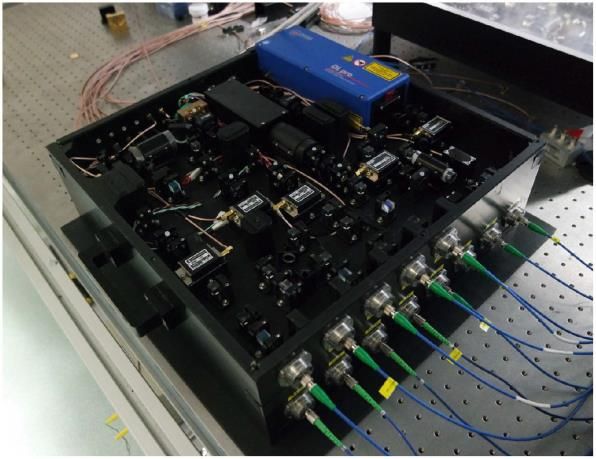
Fig. 3 shows the working principles of a typical cold atom source, which consists of a
magneto-optical trap formed by two coils which generate the magnetic field used to
confine the atoms, and three pairs of counter-propagating laser beams which cool the
atoms down to the µ°K range. Atomic species particularly suited to undergo this process
are alkali metals such as 39K, 87Rb (the workhorse) and 133Cs. From the right-hand figure
we also see that an atomic ensemble cooled to 2µ°K would reach, from a point-like ideal
initial distribution, a transverse dimension of ~30µm in ~1ms, because of its residual
thermal expansion. If the cloud were at room temperature (300°K), after 1ms it would
have reached a transverse dimension of 0.5m. Cooling the atoms is therefore necessary
to have collimated atomic beams which do not expand too quickly as they propagate
along the interferometer.

 Fig. 3: conceptual scheme of a magneto optical trap (MOT), and typical expansion of a cloud of cold atoms as
 compared with atoms at room temperature.

In Fig. 4 we show the atomic states of a 87Rb atom involved in the interferometric
sequence. The two states of interest are a fundamental state | , > and an excited state
| , + ℏ eff >. Optical transitions between these two states are induced by exploiting the
stimulated Raman effect, which makes use of two counter-propagating laser beams with
frequencies 1 and 2 . The momentum of two atomic states differs by ℏ eff = ℏ( 1 − 2 ) ≅
2ℏ 1 , 1 and 2 being the wave-vectors of the counter-propagating beams.

 87
 Fig. 4: Atomic states of a Rb atom and stimulated Raman transitions induced by counter propagating laser
 beams.

 7
Fig. 5 show the evolution of the states in which the atom can be as it propagates along the interferometer. The first laser pulse (known in the literature as a /2 pulse, and actually formed by a pair of counter-propagating pulses), has properties such as intensity and duration finely calibrated to induce with a 50% probability an atomic transition from the fundamental state | , > in which the atom is before entering the interferometer to the excited state | , + ℏ eff >. After such a pulse the atom is in a superposition of the two states, which in rough terms means that it has simultaneously (i) remained in the fundamental state and continued its initial trajectory, following the blue line in Fig. 5, and (ii) transitioned to the excited state, having received a momentum kick of ℏ eff which changed its trajectory to the green line. After an evolution time T the atom is shone upon by a so-called pulse, meaning that it is calibrated in such a way to induce an atomic transition with 100% probability. Therefore the excited state (where the atom is with 50% probability) is turned into the fundamental one, and the fundamental state (where the atom is with 50% probability) is turned into the excited one. This is represented in Fig. 5 by changing colour and direction of both the lines which represent the two trajectories the atom is simultaneously in. Fig. 5: State of the atom as it evolves inside a three-pulse Mach-Zehnder interferometer. In the figure, and 2 are the duration of the /2 and of the laser pulses respectively, while U and L indicate the upper and the lower paths in the interferometer. Let’s give some typical numbers: a cloud with N106 atoms propagates inside an interferometer with a longitudinal velocity v1m/s; the interferometric pulses are separated by time intervals T10·10-3 s, and the total length of the interferometer is therefore v·2T2cm. When excited by a laser pulse, which has a typical duration of 10-6s, an atom acquires an additional transverse velocity component equal to v10-2 m/s, so that the spatial separation between the two atomic paths at the centre of the interferometer becomes v·T 10-4 m. After another time interval T, a second /2 pulse is shone on the atom. Such a pulse turns with 50% probability the fundamental state (where the atom is with 50% probability) into the excited one, and simultaneously it turns with 50% probability the excited state (where the atom is with 50% probability) into the fundamental one. After this pulse the atomic wavefunction is given by the sum of two terms which have equal weight, and are associated respectively with the atom in the fundamental state and in the excited state. These two terms have however different phases: this is due to the fact that each time a laser pulse of the /2--/2 sequence has interacted with the atom it imprinted on the atomic wavefunction a phase shift equal to its optical phase at the time and position of the interaction, with a sign that depends on the atomic transition it has 8
induced. The term of the wavefunction describing the atom exiting the interferometer in
 light
the fundamental state has therefore acquired a phase U determined by the green-blue
upper trajectory U, while the term describing the atom exiting the interferometer in the
 light
excited state has acquired a phase L determined by the blue-green lower path L. To
obtain the atomic probability density we now have to sum these two terms to obtain the
 light light
total atomic wavefunction, and then square it. The phase difference L − U will
therefore appear in the function which gives the probability of finding the atom in either
of its possible states. In other terms, it could be said that the probability that the atom at
the interferometer exit is in its fundamental or in its excited state depends on the
difference between the phases it has accumulated while it was simultaneously travelling
along the two available paths inside the interferometer.
To show how this effect can be exploited for sensing we will now make the example of a
laboratory CAI gravimeter, which measures the acceleration due to a gravitational field .
In this case, the apparatus (and therefore the lasers which generate the optical pulses
which imprint their phases on the atomic wavefunction) is fixed to the ground, and the
trajectories of the atoms assume a parabolic behaviour under the action of the gravity
field, as shown in Fig. 6. The total atomic phase difference between the two paths turns
out to be
 ΔΦ = eff ∙ + ( 1 − 2 2 + 3 )
Here the presence of the contribution eff ∙ is what gives the interferometer its gravity
sensing capability: it is clear that the instrument can be made more sensitive by
increasing the time-of-flight or the momentum eff transferred to the atoms by the
pairs of laser pulses. With 1 , 2 , and 3 are indicated the phases of the three downward
Raman pulses with respect to the upward ones. If there are three pairs of independent
lasers these three relative phases are under the control of the experimenter: the term in
parenthesis can therefore be made to assume the most convenient value, and for
simplicity from now on it will be taken as equal to zero.

 Fig. 6: atomic trajectories in a three pulse interferometer intended to measure the gravitational acceleration.

We are now in the position to better understand why atomic interferometers can be more
sensitive than optical ones. Since the velocity of the atoms inside the interferometer is
much smaller than the velocity of light (~1m/s versus 10 8 m/s), the force we are
interested in will have a much longer time to interact with the atoms and therefore to

 9
modify the paths they take inside the interferometer. This allows even a very tiny force light light to induce a measurable contribution to the phase difference φL − φU which is imprinted onto the atomic wavefunction. The system therefore is not actually exploiting the fact that the atomic wavelength is much shorter than the optical one, since what determines the magnitude of the detected signal is the difference between the optical phases which the laser beams imprint on the atomic wavefunction: the phase difference depends on eff , but not on . With respect to optical interferometry, the advantage is that even a very small force can contribute to this difference: atoms are much slower than photons, and therefore interact for much longer times with the force to be measured. There is however the other side of the coin: the N atoms which form the cloud going across the interferometer are typically in the ~106 range, and since each of them contributes to the signal independently from the others the final measurement will be 1 affected by a shot noise which scales as . In an optical interferometer, where there are √ typically 1016 photons contributing to the signal, the associated shot noise level will be much smaller. Additionally, it must be considered that for a mix of fundamental reasons and technical constraints the /2 and pulses used in the interferometric sequence to act on the atomic wavefunction are much less efficient than an optical beam splitter. Coming back to the example of the gravimeter, let us emphasise that any other effect able to modify the trajectories of the atoms and therefore the time and location at which they encounter the interferometric pulses will give rise to a further contribution to ΔΦ, which would add to the one determined by the gravitational field. Typically, the motion of alkali metal atoms is affected by magnetic fields: on one hand, this means that a CAI-based magnetic field sensor can be envisaged, but on the other it implies that a CAI gravimeter should be accurately shielded from any magnetic field. It is also necessary to damp out any vibrations, since the vertical component of the acceleration associated with such vibrations will end up summed with the gravitational one. It is also possible to use a CAI to measure the acceleration of the atoms propagating inside it with respect to another moving object. A preliminary step is ensuring that the light emitted by the bottom lasers contains both frequencies 1 and 2 , and substituting the top Raman lasers in Fig. 6 with a mirror attached to the moving object with respect to which we want to measure the acceleration of the atoms. This arrangement ensures that the phases of the three reflected pulses depend on the mirror position, and this information is imprinted on the atomic wavefunctions. As an outcome, the interferometer will be measuring the atom acceleration with respect to the moving mirror, or conversely the mirror acceleration with respect to the atoms. As we will see in the next section, this approach can be employed to build a hybrid accelerometer. Let’s assume that the atoms are motionless in a zero-gravity environment, or moving under the influence of a stationary field, while the mirror is the proof mass of an electrostatic accelerometer subject to several disturbances. The signal coming from the CAI accelerometer can be used to drive a feedback loop that feeds an actuator operating on the proof mass, in such a way to suppress its vibrations and drifts. In this hybrid system the CAI accelerometer is used to obtain a reference signal which is employed to suppress the noise affecting the classical accelerometer. In addition to measuring the gravitational field, a CAI gravimeter can also be used to investigate more fundamental issues regarding the theory of gravitation. In this case the object of interest is not the magnitude of the gravitational field, but its possible dependence on the mass it is acting on. Such dependence is not contemplated in Newton’s theory, but is not ruled out by more general physical models of gravitation. If existent, it is expected to give rise to extremely small effects, and this could be the reason why they have never been detected with the techniques employed until now. CAI has therefore been recruited to this aim. Several experimental efforts are underway, which require the propagation in the interferometer of two atomic species with different masses 1 and 2 to detect any possible difference between 1 and 2 . In a satellite, the reduced gravitational pull would allow the atoms to remain for longer times inside the interferometer and therefore increase the sensitivity of the CAI measure. In a 10
microgravity environment, the launched cold atoms move in a uniform velocity: the
interrogation time is therefore determined only by the launching velocity, a parameter
which can be well controlled by the experimenter. In addition, the absence of
gravitational-induced tilts improves the quality of the magnetic confinement.
Let us now imagine a different situation, where no external forces of any kind are acting
on the atoms propagating in the interferometer, and thus they are following straight
inertial paths; conversely, the instrument (and its lasers in particular) is attached to a
moving platform. In these conditions the two paths the atom can take inside the
 light light
interferometer, and therefore the phase difference L − U accumulated by the
wavefunction as the atom propagates along them, will be determined by the acceleration
and the rotation rate of the platform: this means that the interferometer can assume the
role of an inertial sensor such as an accelerometer or a gyroscope. What determines the
output of the interferometer is the relative motion of the atoms and of the lasers
producing the interferometric sequence: if the atoms are on inertial straight paths, the
output will be only determined by the acceleration and the angular velocity of the
instrument frame to which the lasers are fastened.
It should be stressed that also in this case great care should be taken to avoid the
parasitic effects of magnetic fields and vibrations. However, there is an additional
complication: in the presence of a gravitational field, admittedly a quite common
situation, a CAI accelerometer will be measuring the sum of the acceleration with which
the instrument itself is moving and of the gravitational acceleration which is affecting the
motion of the atoms inside it. This follows from the fact that both the motion of the
atoms under the action of the gravitational field and the motion of the instrument itself
(which in this case constitutes the object of our interest) will contribute to determine the
times and positions where the atom meets the laser pulses, and therefore the phase
 light light
difference L − U . Indeed, there is no way to distinguish inertial effects from
gravitational ones. If the instrument is intended for autonomous navigation, it must
therefore be complemented with an independent knowledge of the local gravity field (e.g.
a gravitational map), in such a way that the local gravitational component can be
eliminated from the measured acceleration.
It can be demonstrated that if the interferometer is designed as an inertial sensor the
total phase difference ΔΦ is given by the sum of two contributions Φ and Φ determined
respectively by acceleration and angular velocity; in explicit terms, it is given by
 ΔΦ = Φ + Φ = eff ∙ 2 + 2 eff ∙ ( × ) 2
where and are respectively the acceleration and the angular velocity to be measured,
and is the propagation velocity of the atoms in the interferometer. It is apparent that,
for any given laser-induced transition which fixes eff , the sensitivity of the instrument
increases with the interaction time , because the same signals and/or will generate
a larger phase difference ΔΦ. It can also be seen that acceleration and angular velocity
simultaneously contribute to ΔΦ, so that some tricks must be used to distinguish among
them. A common way to achieve this aim is by using two counter-propagating clouds of
atoms (i.e. with opposite values of ), and then sum and subtract their signals to obtain
respectively and . This approach entails using two separate MOTs and careful
synchronization.
The phase difference determines the transition probability, which is given by

 (ΔΦ) = = 0 − cos(ΔΦ)
 + 2
where and are the relative atomic populations respectively in the excited and in the
fundamental states, 0 is an offset probability ideally equal to 0.5, and is the fringe
visibility ideally equal to 1. Assuming for 0 and their ideal values, we have that a
ΔΦ = 0 leads to = 0 and = 0 (no atoms in the excited state), while ΔΦ = π leads to
 = 1 and = 1 (all atoms in the excited state). Fig. 7 shows how experimental findings

 11
confirm the oscillating pattern predicted by the theory for the transition probability: in
practice, from a measurement of the relative population in the two states we deduce the
phase difference, and from the phase difference we calculate the signal we are interested
in.

 Fig. 7: Experimental points measuring the probability of an atom having transitioned from the fundamental to
 the excited state.

By considering the results shown in Fig. 7, we can also appreciate the deviations from
the ideal behaviour. In particular, the transition probability does not oscillate between 0
and 1, meaning that visibility of the fringes is not unitary and the signal to noise ratio is
somewhat degraded. This follows from several technical factors, and among them
particularly relevant are those impacting on the efficiency with which the laser pulses
induce the desired atomic transitions. One of the factors at play here is that the intensity
transverse profile of a laser beam is not uniform and the atomic cloud occupies a finite
volume of space: as a consequence, only some of the atoms in the cloud will encounter
the exact value of the optical field which is necessary to induce the desired transition, for
a given duration of the pulse. This unavoidably implies that (i) the preparation stage
does not have a perfect efficiency, meaning that not all of the atoms entering the
interferometer are in the desired initial state (ii) some of the atoms will not undergo the
expected transitions in the three-pulse interferometer, thus failing to capture in their
phases the signal to be measured and (iii) some atoms will not be counted at the
detection stage. A possible way to attenuate this problem would be by reducing the
physical dimensions of the atomic cloud, but it should be taken into account that any
reduction in the number of atoms will increase the shot noise. It must also be considered
that the atomic cloud unavoidably grows larger with time, because of the residual
thermal agitation of the atoms. This implies an unescapable trade-off between the
sensitivity of the instrument and the visibility of the fringes, since the sensitivity of the
instrument increase with the time interval spent by the cloud inside the interferometer. A

 12
compromise must also be made between the instrument bandwidth and its sensitivity: a faster instrument requires shorter permanence time 2 of the atomic cloud inside the interferometer, but any reduction of will diminish its sensitivity. An additional feature to be taken into account follows from the fact that the measurement procedure follows a succession of separate steps: a cloud of atoms is cooled, it is launched and initialized, it passes across the interferometer, and, after it has exited, the relative populations in the two sub-clouds it has been split into are detected, thus allowing plotting one of the points in Fig. 7. The procedure is then repeated with a new cloud of atoms. The useful measurement time is the time spent by the atomic cloud inside the interferometer. All the other steps of the measurement procedure contribute to a so-called “dead time”, during which the instrument is only preparing itself for the actual measurement. The dead time constitutes a significant fraction (usually greater than 50%) of the total time necessary to perform a single measurement, and it is mostly due to the time necessary for the MOT to cool the atoms. It has a direct impact on the repetition rate of the instrument, i.e. on the time interval between two successive measurements. Note that if we want to reduce the ballistic expansion of the cloud by reducing the temperature, we would be forced to keep the atom in the MOT for a longer time, thus increasing the instrument dead time. Typically, CAI can make measurements with an overall frequency of some hertz, although several technologies are being tested to improve their repetition rate. It is also apparent that the output/input relation of a sensor based on CAI is (approximately) linear only for phase intervals much smaller than , which typically translates in extremely small signals; in addition the periodicity of (ΔΦ) implies that the same output (as measured by the relative populations in the two atomic states) can be attributed to different values of the phase difference, and therefore different values of the signal. This means that CAI-based inertial sensors have very limited dynamical range, and must work in tandem with other conventional sensors whose sensitivity may be lower but whose dynamical range must be wider. Differently put, to successfully track the CAI inertial signals it is necessary that rapid variations in linear acceleration (jerk) and in angular velocity are limited to an amount equivalent to a /2 interferometer phase shift over one interferometer cycle. This dictates maximum values for the acceptable jerk and angular acceleration, and exceeding these values requires the use of complementary auxiliary sensors. In this hybrid quantum-classical approach classical sensors are typically used also to measure the disturbances (vibration, magnetic field) which must be filtered out. On the other side, a CAI sensor can act as an absolute reference to provide on-site calibration to classical sensors. 13
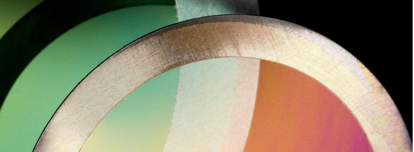
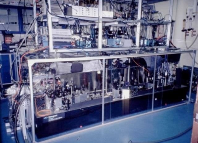
3 Research highlights The material of this section is divided according to the targeted applications, so we will have a first subsection devoted to inertial navigation which describes CAI-based gyroscopes and accelerometers, and a second subsection dedicated to gravimeters. Although a gravimeter is conceptually identical to an accelerometer, the actual use of the two instruments dictates very different constraints and therefore different implementations. An accelerometer usually needs to be less sensitive than a gravimeter, but has higher requirements in terms of dynamical range, speed, size, power consumption, portability, and ruggedness. In it, acceleration must be measured along three different axis, and a six axis instrument measuring also the three components of the angular velocity is necessary to have a sensor which can be employed in an inertial navigation unit. A gravimeter is a simpler one-axis instrument, since it is intended to measures the vertical (and slow-varying) acceleration associated with the Earth gravity field. It however needs to be extremely sensitive and portable, to allow its employment in gravity surveys. However, by surveying the scientific literature, we noticed that very often the same group of researcher address with their efforts both inertial navigation and gravimetry application, and qualify their devices for both uses. In these cases, gravimeters will be considered accelerometers and therefore included in the first subsection, dedicated to inertial navigation sensors. In the second subsection we will give more space to actual measurement campaigns and field deployments of CAI gravimeters than to the instruments technical details. 3.1 Gyroscopes and accelerometers In this Section we present some examples of the research activity on the development of gyroscopes and accelerometers based on cold atom interferometry. For historical reasons, we start by presenting the first experiment which demonstrated an accelerometer based on cold atom interferometry, performed in Stanford in 1991. An atomic fountain with a Mach-Zehnder interferometric scheme based on three stimulated Raman transitions was employed, see Fig. 8. At a 1Hz pulse rate, ~5x10⁷ sodium atoms, confined initially to a ~3mm sphere, were launched on vertical ballistic trajectories. The temperature of the atoms was ~30µ°K, with a rms velocity spread of ~30cm/s. Each pulse of atoms was generated from a three-step sequence which consisted of loading a magneto-optic trap, cooling the trapped atoms, and launching the cooled atoms vertically with a mean propagation velocity of ~2.5m/s. The atoms were trapped and launched in an ultra-high vacuum environment: a liquid nitrogen cooled cryo-shield helped maintain an operating background pressure of ~1x10⁻¹⁰ torr. A sensitivity to accelerations of g/g=3x10-8 was demonstrated for T=50ms drift times, after 2x10 3 seconds of integration time. The authors claimed that by using caesium instead of sodium and by implementing an active vibration isolation system, an absolute sensitivity of g/g
attained by commercial navigation grade ring laser gyroscopes, and their angle random
walk is ~1000 times better than that associated with ring laser gyroscopes or fibre optic
gyroscopes used in navigation-grade inertial navigation systems. According to the
authors, a field implementation of their system would enable navigation with a system
drift less than 1 km/h.

 Fig. 8: CAI accelerometer developed at Stanford, 19924.

 Fig. 9: CAI gyroscope developed at Stanford, 20065.

The Stanford group generated a spin-off company, AOSense, which commercializes cold
atom enabling technologies and devices such as atom beams sources, electronics,
frequency standards, lasers, fibre frequency combs, optical isolators, transfer cavities,
opto-mechanical components, and ion pumps. They have a commercial version of a cold

4
 “Measurement of the gravitational acceleration of an atom with a light-pulse atom interferometer”, M.
Kasevich & S. Chu, Applied Physics B, Vol. 54, 321–332, 1992;
https://link.springer.com/article/10.1007/BF00325375
5
 “Long-Term Stability of an Area-Reversible Atom-Interferometer Sagnac Gyroscope”, D. S. Durfee et al., Phys.
Rev. Lett. 97, 240801, 2006; https://journals.aps.org/prl/abstract/10.1103/PhysRevLett.97.240801
https://arxiv.org/pdf/quant-ph/0510215.pdf

 15
atom gravimeter to be used for geophysics applications, and are working on compact versions of inertial sensors. According to their website, “AOSense is a leading developer and manufacturer of innovative atom optic devices for precision navigation, gravity measurement, and timekeeping. Our capabilities include gyroscopes, accelerometers, inertial measurement units (IMUs), gravimeters, gravity gradiometers, and atomic frequency standards. Atom optic devices use frequency-stable lasers to manipulate atoms freely falling in a vacuum cell, resulting in unparalleled accuracy and stability that greatly surpasses the performance of conventional designs. AOSense was formed in 2004 by Brenton Young and Mark Kasevich to spin-off innovative research developed at Stanford University, joined by Jim Spilker as Chairman. In 2006, AOSense was awarded its first prime contract from DARPA to design, build, and test a gravity gradiometer and single axis accelerometer/gyroscope. Since then, AOSense has successfully designed and built state-of-the-art cold atom technology for numerous government sponsored programs funded by DARPA, Air Force, Army, Navy, NASA, NSF, DTRA, and the intelligence community”. A compact system which allows measuring all the six components of acceleration and angular velocity is needed to build an IMU. A six-axis inertial sensor has been developed in Paris by SYRTE by using two MOT to generate counter-propagating atomic clouds, and laser pulses coming from different directions with respect to the atomic trajectory plane. Such a layout allows measuring both [ , , ] and [Ω , Ω , Ω ], as shown in Fig. 10. Caesium atoms are cooled down to 3 µ°K, and atomic clouds are generated every 0.56 seconds and launched into the interferometer at 2.4 m s-1. The interrogation sequence is achieved with a single pair of Raman beams covering the entire interrogation zone. The atomic velocity and the Raman beam size (30 mm diameter) set the maximum interrogation time to 60 to 80 ms. Acceleration and rotation sensitivity of 4.710-6 m·s-2 and 2.210-6 rad·s-1 have been reached for 1 s averaging time, and of 6.410-7 m·s-2 and 1.410-7 rad·s-1 for 10 min averaging time. For long integration times, the Allan standard deviation approaches a white noise behaviour, thus offering projection-noise-limited performance with a sensitivity to acceleration and rotations of 5.510-7 m·s-2 Hz-1/2 and 2.410-7 rad·s-1 Hz-1/2 respectively. Fig. 10: Six-axis inertial sensors developed in Syrte, 20066. 6 “Six-Axis Inertial Sensor Using Cold-Atom Interferometry”, B. Canuel et al., Phys. Rev. Lett. 97, 010402, 2006 https://journals.aps.org/prl/abstract/10.1103/PhysRevLett.97.010402 https://arxiv.org/pdf/physics/0604061.pdf 16
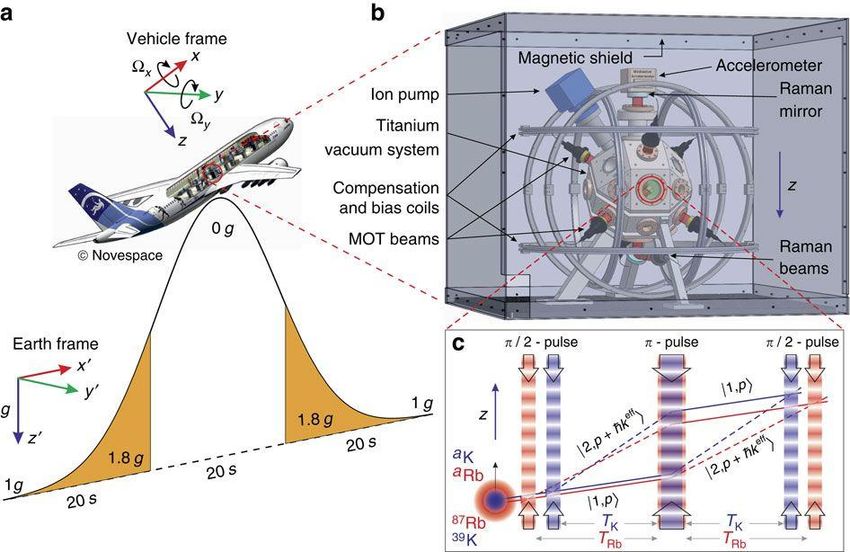
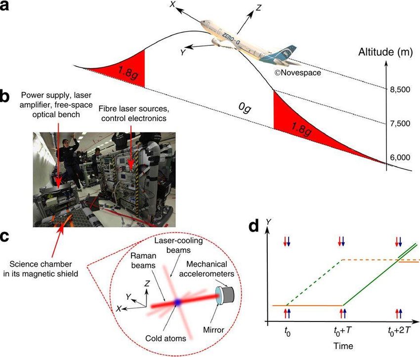
Because of its high sensitivity, running a CAI usually requires low-vibration and high-
thermal stability environments that can only be found in dedicated ground or
underground platforms. The first operation of a matter-wave inertial sensor in an aircraft
was reported by a team including Onera, see Fig. 11. Their matter-wave interferometer
uses 87Rb atoms and operates aboard the Novespace A300 – 0g aircraft, which carries
out parabolic flights during which 22s ballistic trajectories at 0g are followed by 2min of
standard gravity flight at 1g. The interferometer measures the local acceleration of the
aircraft with respect to an inertial frame of reference attached to the free-falling
interrogated atoms. Telecom-based laser sources are used to guarantee high-frequency
stability and power in a compact and integrated setup. Starting from a 87Rb vapour, a
cloud of about 3×10⁷ atoms is cooled down to 10μK; the atoms in the appropriate
magnetic-insensitive state and in the right velocity range are then selected, so that ~106
of them enter the accelerometer. The Raman laser beams are aligned along the plane
wings direction (Y axis) and are retroreflected by a mirror attached to the aircraft
structure and following its motion. The CAI therefore provides a measurement of the
relative mean acceleration of the mirror along the Y axis during the interferometer
duration. In the aircraft, the acceleration along Y fluctuates over time, and is at least
three orders of magnitude greater than the typical signal variations recorded by
laboratory-based matter-wave inertial sensors. To quantify the information contained in
the atomic measurements, mechanical accelerometers (MAs) fixed on the retroreflecting
mirror are employed, and the correlation between the MAs and the CAI is analysed. The
instrument consists therefore of a hybrid sensor that is able to measure large
accelerations due to the mechanical devices, and able to reach a high resolution because
of the atom accelerometer. The CAI signal is limited by the imperfections of the atomic
beam splitters and mirror due to the temperature of the cloud and to the gaussian
intensity profile of the Raman beams, whereas the main contribution to noise comes from
the detection process. On the classical side, better scale factor calibration of the MAs and
the damping of high frequency vibration (>10Hz) are required to improve the setup.

 Fig. 11: Operation of a CAI accelerometer on-board a 0g aircraft, 20117.

7
 “Detecting inertial effects with airborne matter-wave interferometry”, R. Geiger et al., Nature Communications
Vol. 2, N. 474, 2011; https://www.nature.com/articles/ncomms1479

 17
At 1g, the sensitivity level of the combined sensor reaches a level of 1.6×10⁻³ m s−2 Hz-1/2, and is able to measure inertial effects more than 300 times weaker than the typical acceleration fluctuations of the aircraft. At 0g, a vibration noise rejection scheme is investigated: it makes use of a four-pulse scheme to build a two-loop interferometer equivalent to two successive one-loop interferometers head to tail. The resulting signal is given by the coherent subtraction of two spatially and temporally separated inertial measurements, and is therefore expected to be less sensitive to the low-frequency inertial effects. An estimated sensitivity of 2 × 10 −4 m s−2 Hz-1/2 has been obtained, which paves the way for an extension of the method to airborne and spaceborne tests of the universality of free fall with matter waves. A compact inertial sensor was developed by the Rasel group in Hannover, see Fig. 12. An atomic cloud at 10μ°K is launched in the interferometer with a forward velocity of 4.4m/s, so that for a total interferometer time 2T=2ms the interferometer effective length is about 9mm. The atomic ensemble has a radius of 2.2mm in the middle of the interaction zone, while the Raman beams have a diameter of 30mm. With a total interrogation time of 2T=4ms a sensitivity of 2×10 −3m/s2/Hz1/2 for accelerations and 2×10⁻⁴ rad/s/Hz1/2 for rotations is demonstrated. Several technical improvements are suggested which would allow improving these results, and reaching a rotation rates sensitivity of ~10-9 rad/s for one second of measurement. Using an extended interferometer scheme with three independent atom-light interaction zones would further enhance the performances, achieving sensitivities better than 10−8 rad/s/Hz1/2. Fig. 12: Hannover compact CAI gyroscope8. A collaboration involving Sandia targeted a higher measurement frequency by exploiting cold atom recapturing, see Fig. 13: the idea is that recycling as many cold atoms as possible reduces the dead time associated with the cooling process. In their device, two 87 Rb atom ensembles are cooled to 35 µ°K in 1.5 ms inside two MOTs located 3.6 cm apart, and are launched toward one another at a velocity of 2.5 m/s. During their ballistic trajectory, they are interrogated with a stimulated Raman sequence, detected, and then recaptured with an estimated efficiency of 85% in the opposing trap zone. The time between two successive Raman pulses is 4.1ms, and the pulse duration is 1.6 µs. A dual-axis measurement sequence, involving a single vector component for the acceleration and the angular velocity, can be realized in 16.6 ms. Thus is realized a combined accelerometer and gyroscope having a frequency measurement of 60Hz, with sensitivities to acceleration and rotations of 8.810-6 m·s-2 Hz-1/2 and 1.110-6 rad s-1 Hz-1/2 respectively. 8 “A compact dual atom interferometer gyroscope based on laser-cooled rubidium”, T. Müller et al., The European Physical Journal D, Vol. 53, 273–281, 2009; https://link.springer.com/article/10.1140/epjd/e2009- 00139-0 18
Fig. 13: Cold atom recapturing by Sandia, 20149. A sensor hybridization scheme was proposed by Syrte in 2014, see Fig. 14. The author started by observing that the sequential operation of CAI sensors leads to dead times between consecutive measurements, which causes an intrinsic low frequency sampling (~1Hz) of the vibration noise and an aliasing effect of the high-frequency noise components. The use of active or passive isolation platforms to overcome the problem leads to bulky set-ups ill-suited for operation in noisy or mobile environment. Increasing the cycling frequency can attenuate the problem, but at the price of a sensitivity reduction. An alternative method exploits post-correlations between simultaneous measurements from classical and atom accelerometers. This resolves the ambiguity in the fringe number which is typical of cold-atom interferometers: their sensitivity is indeed so high that typical urban vibrations induce atomic phase shifts greater than , which scatters the measurement points away from mid-fringe over several interference fringes. Exploiting ex-post correlation between classical and quantum signal leads however to a sub-optimal sensitivity, as measurement performed at the top and bottom of the fringes have low sensitivity to phase fluctuations. In their work the authors exploit this correlation, but they now pre-compensate the atomic phase fluctuations induced by vibrations in a real-time way, acting on the phase difference of the Raman lasers before the wavepackets are recombined. In addition to suppressing vibration noise, this enhances the instrument sensitivity by keeping it operating at mid fringe. Furthermore, they take the full advantage of these correlations to correct for the drift of the mechanical accelerometer. They claim a short-term sensitivity of 6.5×10⁻⁷ ms−2 at one second measurement time, improving up to 300 s to reach a level of 3×10⁻⁸ ms−2. The hybrid sensor combines the advantages of both sensors, providing a continuous and broadband (DC to 430 Hz) signal which benefits from the long term stability and accuracy of the atomic sensor. These features make it appealing for geoscience (seismology and gravimetry), and are of major relevance in inertial navigation. Indeed, since the high frequency variation of the acceleration is the signal of interest for the calculation of the trajectory of the vehicle, any loss of information induced by dead times constitutes a major limitation. Using the hybrid accelerometer for calibration would allow reaching an error of less than 1 m after 4 h of navigation. 9 “Dual-Axis High-Data-Rate Atom Interferometer via Cold Ensemble Exchange”, Akash V. Rakholia et al., Physical Review Applied, Vol. 2, N. 054012, 2014; https://arxiv.org/pdf/1407.3847.pdf https://journals.aps.org/prapplied/abstract/10.1103/PhysRevApplied.2.054012 19
Fig. 14: Quantum-classical hybridization, Syrte 2014. Left: Open red squares represent the atomic phase shifts estimated from the classical accelerometer, while full black points give the atomic phase shifts measurements when compensated for vibrations in real time. Right: Allan standard deviation of acceleration signals: conventional accelerometer alone (blue line), hybrid accelerometer without (red line) and with (black line) correction from Earth’s tides10. An additional way to improve the performance of CAI has been introduced by Rasel’s group, and exploits the use of composite light pulses to create beam splitters and mirrors. The resulting symmetrized composite-pulse interferometer (SCI) differs from the MZI scheme since it does not require a preparation step prior to the interferometer sequence and the beam splitter and the mirror are composed of a rapid succession of Raman pulses separated by a minimal dark time, see Fig. 15. The immunity of the SCI to noninertial perturbations stems from the fact that most of the time - namely, during the time T of free evolution - the matter waves are in the same electronic state while propagating along the two branches. Therefore, the fluctuations of both the phase of the laser which drives the transition between these states and the external forces which, in general, act differently on the two internal states, only affect the interferometer signal during the comparably small time intervals (single pulse duration) and tS (dark time) and are therefore strongly reduced as compared to the MZI. The suppression of these noise effects is best quantified in terms of the temporal sensitivity function g(t). In Fig. 15 is shown the space-time diagram (x; t) and the corresponding sensitivity function g(t) for (a) a conventional Mach-Zehnder interferometer (MZI) with single Raman pulses (red wavy lines) as atom-optical elements and (b) the symmetrized composite-pulse interferometer (SCI) featuring multiple Raman pulses (multiple red wavy lines) for each atom-optical beam splitter and mirror. Note that as well as tS within a composite pulse are not drawn to scale. The Raman interactions lead to a change of both the electronic state (ground and excited state denoted by solid and dashed lines, respectively) and the kinetic momentum of the wave packet, depending on the direction of the effective photon momentum k (indicated by black arrows). The contrast of the MZI signal depends crucially on the state preparation. A pure sample of excited-state atoms can be achieved by optical pumping after molasses cooling. We recall that molasses cooling makes use of three pairs of circularly polarized laser beams to cool neutral atoms to temperatures lower than a magneto-optical trap (say tens of µ°K instead of hundreds of µ°K); however, unlike a MOT, no trapping is provided. As shown in the figure, a specific velocity class of this sample can be selected with the help of a Raman pulse transferring them into the ground state, while the rest of the excited atoms are removed by a resonant blow-away pulse (yellow wavy lines). In contrast, in the SCI the blow-away pulse is not performed until the first two beam-splitter pulses. As indicated by g(t), which expresses the sensitivity to Raman laser phase noise and magnetic field fluctuations, the 10 “Hybridizing matter-wave and classical accelerometers”, J. Lautier et al., Appl. Phys. Lett. Vol. 105, No. 144102, 2014, https://aip.scitation.org/doi/pdf/10.1063/1.4897358 https://arxiv.org/pdf/1410.0050.pdf 20
You can also read