Commissioning the ATLAS Liquid Argon Calorimeter Phase-I Upgrade
←
→
Page content transcription
If your browser does not render page correctly, please read the page content below
Commissioning the ATLAS Liquid Argon Calorimeter Phase-I Upgrade

                                                              Ellis Kay, on behalf of the ATLAS Liquid Argon Calorimeter Group
                                                           Department of Physics and Astronomy, University of Victoria, Victoria, BC,
                                                                                        V8W 2Y2, Canada
                                                                                    E-mail: ellis.kay@cern.ch

                                                                                                                      ter with full coverage in azimuthal angle1 . It uses liquid
                                                                       Abstract                                       argon as an active medium, with copper electrodes and
                                                                                                                      various absorber materials (see Figure 1). Incident par-
                                          Liquid argon (LAr) sampling calorimeters are employed                       ticles shower in the absorber material and subsequently
                                          by ATLAS for all electromagnetic calorimetry in the                         ionise the LAr. An electric field applied across the LAr
                                          pseudo-rapidity region |η| < 3.2, and for hadronic and for-                 gap causes the ionisation electrons to drift across it, lead-
                                          ward calorimetry in the region from |η| = 1.5 to |η| = 4.9.                 ing to a triangular pulse which is collected by the elec-
                                          In the first LHC run (Run-1), a total luminosity of around                  trodes (see Figure 2). The subdetector is housed in
                                          26 fb-1 was collected at centre-of-mass energies of 7-                      one ‘barrel’ and two ‘endcap’ cryostats kept at -184◦ C.
                                          8 TeV. After detector consolidation during a long shut-                     A high granularity electromagnetic (EM) calorimeter
                                          down, Run-2 started in 2015 and around 150 fb-1 of data                     with an accordion geometry covers the barrel (EMB) re-
                                          at a centre-of-mass energy of 13 TeV was recorded. With                     gion of |η| < 1.475 and the end-cap (EMEC) region of
                                          the end of Run-2 in 2018, a multi-year shutdown for the                     1.375 < |η| < 3.2. Two parallel-plate hadronic endcap
                                          Phase-I detector upgrades began. As part of the Phase-I                     (HEC) calorimeters cover the region 1.5 < |η| < 3.2, while
                                          upgrade, new trigger readout electronics of the ATLAS                       forward calorimeters (FCal), which use cylindrical elec-
                                          LAr Calorimeter have been developed. Installation be-                       trodes running parallel to the beam axis within a honey-
                                          gan at the start of the LHC shut down in 2019 and is                        comb structure of metal, cover the region 3.1 < |η| < 3.9.
                                          expected to be completed in 2020. A commissioning cam-                      Each section of the calorimeter is segmented in depth in
                                          paign is underway in order to realise the capabilities of                   up to three layers, referred to as front, middle and back.
                                          the new, higher granularity and higher precision level-1                    For |η| < 1.8, an additional ‘presampler’ layer provides
                                          trigger hardware in Run-3 data taking. This contribution                    measurements of energy lost upstream of the subdetec-
                                          will give an overview of the new trigger readout system                     tor. The LAr calorimeter, with each of these technologies
ATL-LARG-PROC-2021-004

                                          and the ongoing commissioning and installation efforts.                     mirrored in the A and C sides of the detector, consists of
                                                                                                                      8 subsystems, referred to as ‘partitions’, namely EMBA,
                                                  I.   The ATLAS Liquid Argon Calorimeter
                                                                                                                      EMBC, EMECA, EMECC, HECA, HECC, FCalA and
                                                                                                                      FCalC.
                         30 August 2021

                                                                                                                                       II. Readout Electronics
                                                                                                                      The ionisation signals from the 182 486 LAr readout chan-
                                                                                                                      nels leave the cryostats via 114 feedthroughs. Each
                                                                                                                      feedthrough is connected to one of the Half-Front-End-
                                                                                                                      Crates (HFECs), which sit radially around the detector
                                                                                                                      and house several kinds of electronic boards connected to
                                                                                                                      a baseplane. Front-End Boards (FEBs) [5] are responsible
                                                                                                                      for receiving the analogue signals from up to 128 chan-
                                                                                                                      nels and sampling and digitising them before transmitting
                                                                                                                      them, via optical links, to the back-end electronics which
                                                                                                                      reside in an underground service cavern separate from the
                                                                                                                         1
                                                                                                                           ATLAS uses a right-handed coordinate system with its
                                                                                                                      origin at the nominal interaction point (IP) in the centre of
                                                                                                                      the detector and the z-axis along the beam pipe. The x-axis
                                          Figure 1: The ATLAS liquid-argon calorimeter system [1]. The different      points from the IP to the centre of the LHC ring, and the y-
                                          sections of the subdetector are labelled, along with their respective ab-   axis points upward. Cylindrical coordinates (r, ϕ) are used in
                                          sorber materials. Photographs of the different structures of the forward    the transverse plane, with ϕ being the azimuthal angle around
                                          calorimeters (FCal) and electromagnetic barrel (EMB) calorimeters are       the z-axis. The pseudorapidity is defined in terms of the polar
                                          overlaid [2].
                                                                                                                      angle θ as η = − ln tan(θ/2). In ATLAS, the ends of the
                                                                                                                      detector with positive and negative z coordinates are referred
                                            The ATLAS LAr calorimeter [3] is a sampling calorime-                     to as ‘A-side’ and ‘C-side’, respectively.

                                          Copyright 2021 CERN for the benefit of the ATLAS Collaboration. Reproduction of this article or parts of it is allowed as specified in the
                                          CC-BY-4.0 license.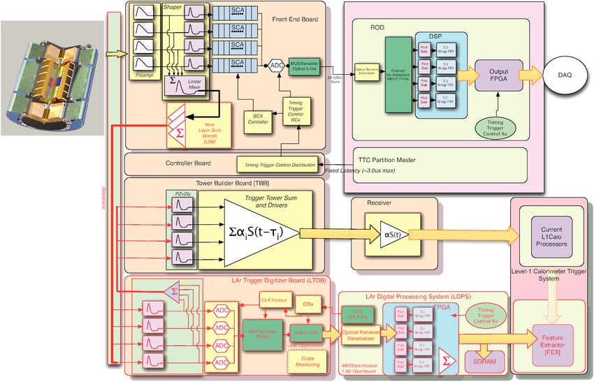
algorithms will have better discrimination between pho-
tons, electrons, taus and jets, and new Feature EXtractor
(FEX) modules will use topological shower shape vari-
ables to discriminate between these different objects [8].
Such improvements require higher granularity informa-
tion from the LAr calorimeter than what is provided in
the Run-2 trigger readout path. Currently, signals from
cells in different calorimeter sampling layers are grouped
into ~ 5 400 trigger towers, as described in the previous
section. As a result of this summing, information about
Figure 2: Diagrams of the structure of a sampling layer of the ATLAS the development of shower shapes is lost, and cannot be
EM calorimeter (left) and a pulse shape read out from the detector
before and after shaping and sampling (right) [4]. used as a discriminating variable in the trigger decision.
In the Phase-I upgrade, cells will instead be grouped into
~ 34 000 ‘Super Cells’ (SCs), which provide up to four-
experiment. The signal from each channel is split into one layer information and a tenfold increase in granularity.
of three gains (low, medium and high) and, for each gain, Figure 3 shows a depiction of an electron energy deposit
the triangular ionisation pulse is shaped with a bipolar as seen through a TT compared to the same deposit mea-
(CR-(RC)2 ) analogue filter. The shaped signals are sam- sured by SCs for a typical EM η, ϕ slice. In this case, the
pled at the LHC bunch-crossing frequency of 40 MHz and SCs provide information for ∆η × ∆ϕ = 0.1 × 0.1 for the
the samples are stored in a Switched Capacitor Array presampler and back layers and ∆η × ∆ϕ = 0.025 × 0.1
(SCA) analogue memory buffer while awaiting a Level-1 for the front and middle layers. Figure 4 shows the
(L1) trigger accept. In addition to reading out the indi- expected improvement in performance from the Phase-
vidual calorimeter channels, the FEB performs the first I LAr upgrade.
stages of summing in preparation of analogue sums which
are used by the L1 trigger system [6] to inform L1 accepts.
Each of the shaper chips in the FEB outputs a partial
sum of input channels, which are routed to two mezza-
nine boards known as Layer Sum Boards (LSBs) which
perform further summing, depending on the number of
layers in the relevant detector region. These sums are sent
through the HFEC’s baseplane to Tower Builder Boards
(TBBs) or Tower Driver Boards (TDBs), which sum data
from calorimeter cells in all layers in so-called Trigger
Towers (TTs), which correspond to slices of the detec- Figure 4: Expected performance of the Phase-I trigger upgrade [7]. In
tor of approximately ∆η × ∆ϕ = 0.1 × 0.1. The HFECs the plot on the left, the percent difference between the ET of elec-
offline
trons reconstructed offline (ET ) and using the Run-2 L1 is shown
also contain calibration boards, which are used to inject in red, while the difference between this offline reconstruction and the
known triangular pulses into the cryostat in order to sim- energy from SCs is shown in blue, where the ET has been simulated
using Z → e+ e− events in the EMB calorimeter. The plot on the right
ulate the LAr ionisation signal and calibrate the electron- shows expected L1 trigger rates for L = 3 × 1034 cm-2 s-1 as a function
ics. of the EM ET threshold for the case of the Run-2 trigger (blue) and the
Phase-I trigger scheme with different selections of shower shape vari-
ables (black and green). A red line indicates the L1 limit of 20 kHz for
III. Phase-I Upgrade electromagnetic objects, which will remain in Run-3.
In order to transmit this higher granularity informa-
tion from SCs to the L1 Calorimeter (L1Calo) system,
the LAr front-end and back-end electronics must be up-
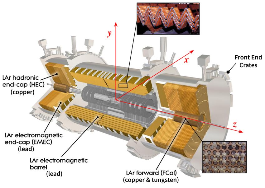
graded. Figure 5 shows a schematic of the readout elec-
tronics, with these new changes shown in red. The most
notable change to the front-end is the introduction of 124
new LAr Trigger Digitiser Boards (LTDBs), which serve
to digitise the analogue signal of supercells, processing up
Figure 3: Diagrams showing the energy deposited by an electron with
ET = 70 GeV as seen by a trigger tower (left) and by the equivalent
to 320 SC signals each. There are seven different ‘flavours’
SCs for a typical region in the EM calorimeter [7]. of these boards depending on their location, with one
flavour for the barrel and six for the end-caps. In order to
The instantaneous luminosity and pileup will increase accommodate this new addition, the baseplanes in each
for Run-3 of the LHC, yet the current ATLAS trigger FEC must be replaced with new ones, which have the nec-
system does not allow for a proportionate increase of the essary number of slots. These new baseplanes also deal
L1 trigger rate. In order to compensate for this while with changes to the signal path which are introduced in
maintaining similar triggering performance, an improve- this upgrade, including the routing of legacy trigger tower
ment of the trigger system itself is required. Upgraded L1 sums for some layers through the LTDB to the TBB, and
Figure 5: Schematic of the Phase-I upgrade architecture [7]. The new components are indicated by the red outlines and arrows. The main readout
path (from FEBs to DAQ) and legacy trigger path (from FEBs to L1 via TBB) are also shown.

the routing of SC sums through the LSBs to the LTDB.                                         IV. Installation Status
The latter path also requires an exchange of the LSBs on
all FEBs. The reception of this digital SC data and its
transmission to the new FEXes is handled by new back-
end hardware, collectively referred to as the LAr Digital                Over the course of the ongoing Long Shutdown (LS2) of
Processing System (LDPS). This system, connected to                      the LHC in preparation for Run-3, the installation of the
the LTDBs through a total of 7 000 optical fibres, serves                new front-end and back-end LAr electronics has been pro-
to receive ADC data and align timing, compute ET for                     gressing. The removal and replacement of all baseplanes
individual SCs in each bunch crossing, sum ET for SCs                    on the detector has been completed. This required, as a
over defined areas of the detector and send the result                   first step, the removal of all boards in each HFEC; a chal-
to the L1 trigger modules. The LDPS consists of ad-                      lenging tasks in a restricted space. In order to exchange
vanced mezzanine cards, named LAr Trigger prOcessing                     the LSB on each FEB, every one of these boards needed
MEzzanines (LATOMEs), and Advanced-TCA (ATCA)                            to be removed from the cavern and refurbished. This has
LAr Carrier (LArC) blades with Rear Transition Module                    been achieved for all FEBs on the detector. Simultane-
(RTM) cards and Intelligent Platform Management Con-                     ously, the cooling plates which surround each board were
troller (IPMC) mezzanine cards [9]. Each set of LArC                     replaced with newly manufactured ones, as well as the
and four LATOMEs is referred to as a LAr Digital Pro-                    ageing hoses that supply cold water to each board.
cessing Blade (LDPB). In total, the LDPS consists of 116
                                                                            The installation of LTDBs continues at the time of this
LATOMEs and 30 LArCs distributed across three ATCA
                                                                         publication. All LTDBs were manufactured, tested and
shelves.
                                                                         delivered to CERN, with just six barrel (EMBC) and four
   The main readout path, as described in section II, re-                end-cap (EMECC) boards awaiting installation due to a
mains unchanged by this upgrade, though data must pass                   lack of access to the relevant regions of the detector.
through the new baseplanes and refurbished FEBs. The
legacy trigger path will be maintained during Run-3, run-                  The back-end installation of LDPBs is complete for the
ning concurrently with the new digital trigger, and should               equivalent LTDBs, with data fibres fully connected be-
also be unchanged, though trigger tower sums for some                    tween the LTDBs and LATOMEs for all of the ATCA
layers will be routed through the new LTDBs.                             crates set up in the ATLAS service cavern.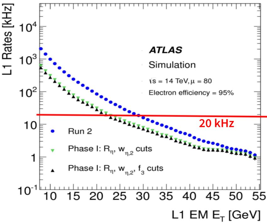
V. Main Readout Path Validation                                           VI.    Legacy Trigger Path Validation
                                                                           As described in section III, the analogue legacy sums
Although the main readout path is unchanged by the                         for some layers will be routed through the LTDBs be-
Phase-I upgrade, much of the contributing electronics has                  fore reaching the TT builders in the upgraded electronics
undergone refurbishment. Signals pass through new base-                    scheme. This increased path through the system will in-
planes to FEBs whose LSBs have been exchanged, and                         troduce a delay in the L1 system for reception of the sig-
some of these FEBs have been returned to different posi-                   nal between different layers, which must be measured and
tions within the HFECs, or to different HFECs entirely.                    accounted for in the trigger decision. Measuring these de-
Checking data from the main readout path is therefore an                   lays is an important step in validating the new hardware,
important first step in confirming that the system is per-                 since the introduced timing difference must reflect the ex-
forming as it was before any disturbances due to installa-                 pected performance of the system. Gain and timing scans
tion. Basic low-level checks such as connectivity scans are                performed in collaboration with the L1 trigger group are
used to ensure that all FEBs and channels are connected                    taken upon the refurbishment of each crate in order to
properly, while full calibration sets with comparisons to                  check connectivity and measure this delay between the
reference runs from the end of Run-2 provide a detailed                    sums from different layers. Figure 7 shows the delays ob-
check that the pulses read from the detector look the                      tained from these timing scans for each layer in EMBA. A
same as before, confirming that the electronics are sta-                   timing difference of up to 10 ns is observed between some
ble. Three different types of calibration runs, namely,                    layers, which is consistent with the expected change due
pedestal, delay and ramp runs, are used in order to cal-                   to the increased path through the LTDB.
ibrate the system and validate the readout electronics.
Pedestal runs involve reading the detector output with
no input signal, providing pedestal information from the
average read out signal (ADC), noise from the RMS and
autocorrelation from the timing correlation of the sam-
ples. Delay runs consist of injecting pulses with a single
input signal current (DAC) with an increasing time shift
in steps of 1.04 ns in order to reconstruct the full pulse
shape. Ramp runs, where signals of increasing DAC are
injected, provide the gain slope, which is extracted from a
fit of the DAC versus ADC curve. Figure 6 shows, as an
example, the comparison between pedestal RMS values
measured before and after the installation process for the                 Figure 7: The signal delays introduced by the Phase-I front-end elec-
                                                                           tronics for L1Calo trigger signals, collected from all trigger towers in
middle layer of EMBA. The data are in clear agreement,                     EMBA [10]. Signals from the region 0 < η < 1.5 and 1.8 < η < 2.2
confirming that the system is stable and the hardware                      are excluded, since these were covered by Phase-I test electronics which
                                                                           were installed during Run-2.
upgrades have not impacted this readout path. Such sta-
bility has been seen for all calibration run types in all of
the refurbished crates.                                                               VII. Digital Trigger Path Validation
                                                                           In order to validate the full digital trigger front-end and
                                                                           back-end path, the different calibration runs, as described
                                                                           in section V, are used, with ADCs for full SCs read from
                                                                           the LATOME output, as opposed to the individual LAr
                                                                           cell data from the main readout path. This validation re-
                                                                           quires the full chain of the Phase-I system, starting with
                                                                           configuration of the LTDBs and LDPS to take data. Spe-
                                                                           cial calibration patterns must also be developed, in or-
                                                                           der to pulse all of the cells in each tested SC. Overnight
                                                                           pedestal or pulsed runs are taken in order to monitor
                                                                           the stability of the system. These runs are also used
                                                                           to extract information such as the pedestal value and
Figure 6: The mean value of the RMS of the pedestal for a given η          peak position for the pulses from each LATOME, which
range measured during a reference run at the end of Run-2 (black line)
compared to values measured after the front-end refurbishment (pur-        is obtained using data processing software which is au-
ple dots) during LS2 [10]. The data shown is only taken from the           tomatically applied to the raw data following each run.
second layer√ of EMBA. The displayed uncertainties are computed as
σrms,cells / Ncells , where σrms,cells is the RMS of the RMS values        Full pedestal, delay and ramp calibration sets are taken
over the cells in the given η range and Ncells is the number of cells in   for each fully refurbished and upgraded crate. Figure 8
the given η range. The step at η=0.8 can be attributed to a change of
the electrode geometrical structure in this region.                        shows examples of processed calibration data from a gain
                                                                           and ramp run for a SC in EMBA. Here we see a pulse
                                                                           shape from the delay run, which has the expected bipolar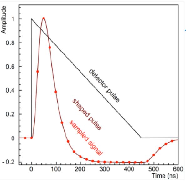
form, and an ADC versus DAC curve from the ramp run.                      difficult time. I would also like to thank my colleagues in
In the latter plot, the ADC increases linearly with de-                   the ATLAS Liquid Argon Calorimeter group for afford-
posited transverse energy up to around 800 GeV, where                     ing me the opportunity to present this content on their
saturation of the SC pulse occurs. Such saturation is                     behalf.
expected to occur in some channels for very high ener-
gies. Unlike the main readout, no reference data exists                                               References
for this newly installed system, therefore validation of the               [1]   ATLAS Collaboration, “The ATLAS Experiment at the
digital trigger requires checking that the calibration data                      CERN Large Hadron Collider,” JINST, vol. 3, S08003,
behaves as expected based on the predicted performance.                          2008. doi: 10.1088/1748-0221/3/08/S08003.
In many cases, select variables from the processed data                    [2]   P. Krieger, “The atlas liquid argon calorimeter: Con-
                                                                                 struction, integration, commissioning and performance
(such as pulse position or gain slope) are compared to ex-                       from selected particle beam test results,” in IEEE
pected thresholds, which are determined through an un-                           Nuclear Science Symposium Conference Record, 2005,
derstanding of the expected SC output. From these runs,                          vol. 2, 2005, pp. 1029–1033. doi: 10.1109/NSSMIC.2005.
calibration constants used for energy reconstruction are                         1596428.
                                                                           [3]   ATLAS Collaboration, “ATLAS Liquid Argon
obtained, and the offline ET can be compared to what is                          Calorimeter: Technical Design Report,” ATLAS-TDR-
computed by the LATOME. For the LATOMEs tested so                                2; CERN-LHCC-96-041, 1996. [Online]. Available:
far, this ET is found to be in good agreement.                                   https://cds.cern.ch/record/331061.
                                                                           [4]   ATLAS Collaboration, “Drift Time Measurement in the
                                                                                 ATLAS Liquid Argon Electromagnetic Calorimeter us-
                                                                                 ing Cosmic Muons,” Eur. Phys. J. C, vol. 70, p. 755,
                                                                                 2010. doi: 10 . 1140 / epjc / s10052 - 010 - 1403 - 6. arXiv:
                                                                                 1002.4189 [hep-ex].
                                                                           [5]   N. J. Buchanan et al., “ATLAS liquid argon calorime-
                                                                                 ter front end electronics,” Journal of Instrumentation,
                                                                                 vol. 3, no. 09, P09003–P09003, Sep. 2008. doi: 10.1088/
                                                                                 1748 - 0221 / 3 / 09 / p09003. [Online]. Available: https :
                                                                                 //doi.org/10.1088/1748-0221/3/09/p09003.
                                                                           [6]   ATLAS Collaboration, “ATLAS Level-1 Trigger: Tech-
Figure 8: Calibration data read from the Phase-I trigger path [11]. The
plot on the left shows the measured pulse shape of a SC in EMBA,                 nical Design Report,” ATLAS-TDR-12; CERN-LHCC-
obtained from delay run with an injected charge of DAC = 4 400 (cor-             98-014, 1998. [Online]. Available: https://cds.cern.ch/
responding to a transverse energy of 487 GeV). The plot on the right             record/381429.
shows the measured amplitude (ADC) of calibration pulses as a function
of injected charge (DAC) from a ramp run for this same SC.                 [7]   ATLAS Collaboration, “ATLAS Liquid Argon
                                                                                 Calorimeter Phase-I Upgrade: Technical Design Re-
                                                                                 port,” ATLAS-TDR-022; CERN-LHCC-2013-017,
                                                                                 2013. [Online]. Available: https://cds.cern.ch/record/
                        VIII.    Conclusion                                      1602230.
                                                                           [8]   ATLAS Collaboration, “ATLAS TDAQ System Phase-
In this contribution, an overview of the installation and                        I Upgrade: Technical Design Report,” ATLAS-TDR-
commissioning of the ATLAS LAr Calorimeter Phase-I                               023; CERN-LHCC-2013-018, 2013. [Online]. Available:
upgrade has been presented. Excellent progress has been                          https://cds.cern.ch/record/1602235.
made in the installation, despite additional challenges                    [9]   CERN-IPMC: Technical Overview. [Online]. Available:
brought on by recent global events, with almost the full                         https://cern-ipmc.web.cern.ch/doc.
front-end and back-end electronics installed, pending ac-                 [10]   Level-1 Calorimeter Trigger Public Results. [Online].
                                                                                 Available: https : / / twiki . cern . ch / twiki / bin / view /
cess to the remaining sections of the detector. The com-                         AtlasPublic/L1CaloTriggerPublicResults.
missioning of crates involves checks of the main readout,                 [11]   LAr Calorimeter LS2 Public Results. [Online]. Avail-
legacy trigger and digital trigger path. The main readout                        able: https : / / twiki . cern . ch / twiki / bin / view /
checks have shown that the system is stable, with no de-                         AtlasPublic/LArCaloPublicResultsLS2.
viations from the performance seen at the end of Run-2,
and the legacy trigger checks show the expected timing
shifts introduced by LTDBs. Connectivity and mapping
checks, as well as full calibration sets are being used to
check newly connected Phase-I hardware, with automatic
processing and comparisons to newly defined thresholds
used to validate each crate. These tools will be used to
sign-off all of the upgraded HFECs and to prepare for
processing real data in upcoming pilot runs and Run-3,
which starts in March of 2022.

                        Acknowledgments
I would like to thank the organisers of ANIMMA 2021,
for inviting me to present these results and for organis-
ing a rich programme of diverse content, even during this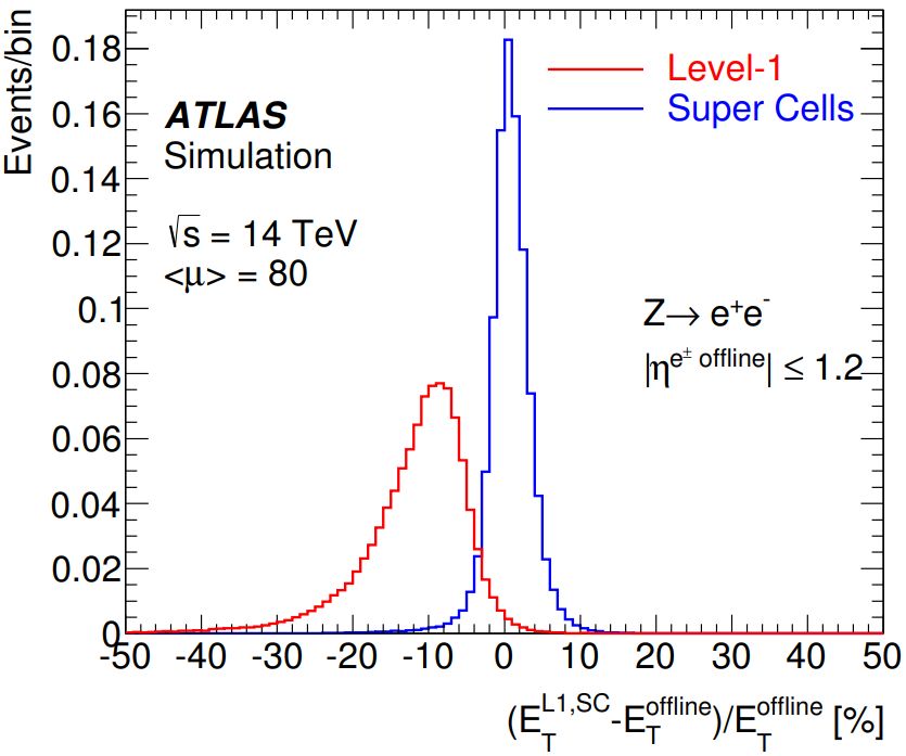
You can also read