Compact Design of a Hydraulic Driving Robot for Intraoperative MRI-Guided Bilateral Stereotactic Neurosurgery - HKU
←
→
Page content transcription
If your browser does not render page correctly, please read the page content below
IEEE ROBOTICS AND AUTOMATION LETTERS, VOL. 3, NO. 3, JULY 2018                                                                                   2515

     Compact Design of a Hydraulic Driving Robot for
          Intraoperative MRI-Guided Bilateral
               Stereotactic Neurosurgery
   Ziyan Guo , Ziyang Dong, Kit-Hang Lee , Chim Lee Cheung, Hing-Choi Fu, Justin D.L. Ho, Haokun He ,
                        Wai-Sang Poon, Danny Tat-Ming Chan, and Ka-Wai Kwok

   Abstract—In this letter, we present an intraoperative mag-                     disease (PD) and dystonia), psychiatric abnormalities and
netic resonance imaging (MRI)-guided robot for bilateral stereo-                  epilepsy. PD alone is the second most common disease of the
tactic procedures. Its compact design enables robot’s opera-                      nervous system after Alzheimer’s disease, and is projected to
tion within the constrained space of standard imaging head
coil. magnetic resonance (MR) safe and high-performance hy-                       affect over 8.7 million people worldwide by 2030 [1]. Deep
draulic transmissions are incorporated. A maximum stiffness                       brain stimulation (DBS) is one of the common stereotactic pro-
coefficient of 24.35 N/mm can be achieved with transmission                       cedures, which is a surgical treatment for debilitating motor
fluid preloaded at 2 bar. Sufficient targeting accuracy (aver-                    symptoms of PD and dystonia. Two long (e.g., 300 mm) slen-
age within ࣘ1.73 mm) has been demonstrated in a simulated                         der (ࣈØ1.3 mm) DBS needles will be individually guided by a
needle insertion task of deep brain stimulation. A novel MR-
based wireless tracking technique is adopted. It is capable of                    stereotactic frame and inserted through burr holes (ࣘ Ø14 mm.)
offering real-time and continuous (30–40 Hz) three-dimensional                    into the patient’s skull. Stimulation electrodes embedded at the
(3-D) localization of robotic instrument under the proper MR                      tip of needle will then be implanted to the deep brain areas of
tracking sequence. It outperforms the conventional method of us-                  interest, thus delivering programmed electrical impulses.
ing low-contrast passive fiducials that can only be revealed in the                  Although the standard workflow of stereotactic neurosurgery
MR image domain. Two wireless tracking units/markers are in-
tegrated with the robot, which are two miniaturized coil circuits                 has been established for over half a century, the operation still
in size of 1.5 × 5 × 0.2 mm3 , fabricated on flexible thin films. A               remains challenging due to its complicated workflow and high
navigation test was performed under the standard MRI settings in                  demand for surgical accuracy. The average recorded error of 2–
order to visualize the 3-D localization of the robotic instrument.                3 mm is just barely tolerable [2]. Stereotactic navigation could
MRI compatibility test was also carried out to prove the mini-
                                                                                  be further complicated by substantial deformation of intracra-
mal interference to MR images of the presented hydraulic robotic
platform.                                                                         nial contents, namely “brain shift”, which occurs inevitably after
                                                                                  craniotomy. The shift is mainly caused by gravity, cerebrospinal
  Index Terms—MRI-guided interventions, stereotactic neuro-
surgery, surgical robotics.                                                       fluid (CSF) leakage, anesthesia and surgical manipulation. It
                                                                                  could induce misalignment (as large as 10–30 mm [3]) of the
                            I. INTRODUCTION                                       pre-operative (pre-op) planning path, aiming beyond the actual
                                                                                  target. In conventional DBS guided by fluoroscopy/computed
     TEREOTAXY is a technique that can locate targets of sur-
S    gical interest using an external coordinate system as refer-
ence. Its application in functional neurosurgery mostly aims
                                                                                  tomography (CT), microelectrode recording (MER) is adopted
                                                                                  frequently to confirm the acceptable placement of electrodes
                                                                                  while assessing the corresponding symptoms with the awake pa-
to treat a variety of movement disorders (e.g., Parkinson’s                       tient under local anesthesia. These complications pose increas-
                                                                                  ing expectation on intra-operative (intra-op) magnetic resonance
   Manuscript received September 10, 2017; accepted February 2, 2018. Date        imaging (MRI)-guided stereotaxy. Unlike fluoroscopy/CT, MRI
of publication March 9, 2018; date of current version March 29, 2018. This        can directly visualize the critical brain structures and targets of
letter was recommended for publication by Associate Editor T. Haidegger and
Editor K. Masamune upon evaluation of the reviewers’ comments. This work          interest (e.g., subthalamic nucleus (STN), globus pallidus in-
was supported in part by Signate Life Sciences Limited, in part by the Croucher   terna (GPi) or ventral intermediate nucleus).
Foundation, and in part by the Research Grants Council of Hong Kong (Refs.           Currently, there are very limited choices of MR safe stereo-
27209515, 17227616, and 17202317). (Corresponding author: Ka-Wai Kwok.)
   Z. Guo, Z. Dong, K. H. Lee, C. L. Cheung, H. C. Fu, J. D. L. Ho, H. He,        tactic systems [2], [4] (e.g., NexFrame, Medtronic Inc., USA
and K. W. Kwok are with the Department of Mechanical Engineering, The Uni-        and ClearPoint, MRI Interventions Inc., USA). They gener-
versity of Hong Kong, Hong Kong (e-mail:,guoziyan@connect.hku.hk; ziyang.         ally require intensive manual adjustment of the stereotactic
dong.matthew@gmail.com; briankhl@hku.hk; zardchim@hku.hk; sk001031@
gmail.com; jdlho@connect.hku.hk; hkhe0812@outlook.com; kwokkw@hku.                frame, and the patient to be transferred in-and-out of the scan-
hk).                                                                              ner bore. This eventually disrupts the workflow. To this end,
   W. S. Poon and D. T. M. Chan are with the Division of Neurosurgery, Prince     MR safe/conditional robotic platforms have been introduced.
of Wales Hospital, Hong Kong (e-mail:, wpoon@cuhk.edu.hk; tmdanny@
surgery.cuhk.edu.hk).                                                             An FDA approved prototype, SYMBIS (formerly called Neu-
   Digital Object Identifier 10.1109/LRA.2018.2814637                             roArmg, IMRIS Inc., Canada), is an MRI-compatible robot built

                         2377-3766 © 2018 IEEE. Personal use is permitted, but republication/redistribution requires IEEE permission.
                             See http://www.ieee.org/publications standards/publications/rights/index.html for more information.
2516                                                                        IEEE ROBOTICS AND AUTOMATION LETTERS, VOL. 3, NO. 3, JULY 2018

predominantly for tele-operated microsurgery, and only one of
its robot arms capable of MRI-guided stereotaxy [5]. This MRI-
compatible robot arm is actuated by piezoelectric motors and the
robot body is made of titanium or polyetheretherketone (PEEK)
to ensure its MRI compatibility [6]. It can be mounted on the
magnet bore, providing constant spatial relation with the magnet
isocenter and the patient’s anatomy. However, it creates a large
footprint in the surgical theater while transferring the intra-op
scanner in-and-out for each imaging update, introducing much
procedural complexity.
   Neuroblate (Monteris Medical Inc., USA) is a robotic probe
with 2 degrees of freedom (DoFs) (rotation and translation)
driven by piezoelectric motors for stereotactic laser ablation
[7]. The probe can be passively oriented by AXiiiS stereotactic
                                                                      Fig. 1. Slave module of the proposed MR safe robot for intra-op MRI-guided
miniframe, which consists of a ball-socket, three legs and a 360°     bilateral stereotactic procedures.
directional interface. Real-time MR-thermometry data can be
provided to ensure safe ablation boundaries from surrounding
structures [8]. For multiple surgical paths, the patient will be             confined workspace of an MR imaging head coil. It is also
transferred back to the operating theater to remove the probe,               actuated by a set of high-performance hydraulic trans-
relocate/realign the frame and create new craniotomy.                        missions which are MR safe/induce minimal imaging
   A research prototype developed by Fischer et al. [9], [10]                artifacts.
towards needle-based neural interventions was reported. The             iii) MRI-guided navigation incorporated with wireless MR-
robot is kinematically equivalent with the conventional stereo-              based tracking coil units, offering real-time positional
tactic frame (e.g., Leksell frame, Elekta AB, Sweden) and is                 feedback directly in MR image coordinates. This avoids
actuated by piezoelectric motors as well. A control system for               any process of offline registration between coordinates
these motors is specially designed to allow the simultaneous                 of the tracking and imaging space.
MR imaging and robot motion, ensuring sufficient image qual-
ity for surgical guidance. The robot can be fixed on the surgical
                                                                                               II. METHODOLOGY
table. However, to complete the whole procedure inside the MRI
scanner, it may require a specialized MRI head coil or scanner           The proposed robot (Fig. 1) is designed to perform bilateral
with larger spatial clearance for robot’s operation (1.5/3 T MRI      instrument navigation in particular for the use of intra-op MRI-
scanners usually with inner diameter of Ø600 mm).                     guided DBS. Anatomical target, STN, is ellipsoid alike and
   Compactness and MRI compatibility are two crucial issues           typically situated in the deep region of brain (90 mm beneath
regarding the feasibility and adaptability of robots in the regular   the skull) [15]. Accuracy of the electrode placement must be
hospital setup. Very few robotic platforms can fit with the MRI       less than 3 mm in order to maintain optimal stimulation effect.
head coil, and also operate during continuous imaging without         The robot design criteria are stated in the following section.
degrading the image quality. None of the aforementioned plat-
forms can accommodate the trend towards bilateral DBS, which
becomes the most popular approach for PD [11]. In addition,           A. Robot Design Criteria
positional tracking in almost all of them is conducted using ei-         Two burr holes are created on the skull for the procedure.
ther optical tracker or passive MR fiducials, which introduces        The proposed robot consists of two manipulators (Fig. 2) which
significant error while registering the robot coordinates with the    will be mounted on the middle line of the two burr holes. Each
imaging ones [12]. MR-based tracking involves tiny coils (e.g.,       provides 4-DoF manipulation of the instrument access to the
Ø3 × 8 mm3 [13]) designed to resonate with MR Larmor fre-             corresponding hole, including pitch, roll, and offsets along X-Y
quency. It enables real-time localization of robotic instruments.     plane above the skull surface. This facilitates alignment of the
In general, there is no robotic system for functional neurosurgery    instrument with the desired straight-line trajectory to the STN.
incorporated with MR safe actuation and MR-based tracking,            Fine adjustments ranged in either X or Y direction of ±2.5 mm,
capable of performing stereotactic manipulation inside the MRI        and pitch angle of ±33°, and roll angle of ±26° are more than
bore [14]. Therefore, the contributions of our work in this letter    sufficient to cover the required workspace in many cases [15].
can be well-differentiated as follows:                                   Provided with the intra-op 3-dimensional (3D) MR images
     i) Development of the first intra-op MRI-guided robot ca-        (e.g., acquired by gadolinium-enhanced T1-weighted volumet-
        pable of performing bilateral neuro-stereotaxy based on       ric scan), surgeons can identify the mid-commissural point
        a single anchorage on the patient skull. Navigation for       (MCP), as well as the STN targets based on the anterior
        both bilateral targets can be performed independently         commissure-posterior commissure (AC-PC) line, thereby deter-
        and simultaneously.                                           mining the desired entry point and insertion path to the target.
    ii) A light-weight (145.4 g) and compact (110.6 × 206.8 ×         Note that the robot must be operated in the deep brain target
        33.2 mm3 ) robot designed to operate within the               coordinates frame, which is defined on the basis of the AC-PC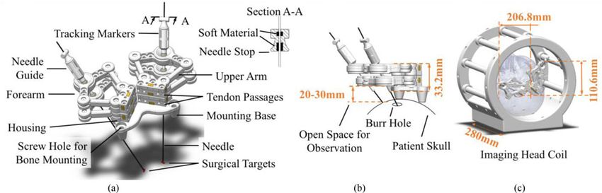
GUO et al.: COMPACT DESIGN OF A HYDRAULIC DRIVING ROBOT                                                                                                2517

                                                                                      Ø2/0.5 mm). The sheath material is axially-incompressible to
                                                                                      prevent sudden/excessive pulling force applied on the skull. It
                                                                                      also supports the route of tendon with sufficient pliability even
                                                                                      under the high tensile strength. The tendon-sheath friction is
                                                                                      reduced by proper lubrication. Two idlers are used to pre-load
                                                                                      the tension in order to reduce any mechanical backlash.
                                                                                         The master (in control room) and slave (in MRI room) ac-
                                                                                      tuation system consists of two identical pinion-and-rack units
                                                                                      to transfer the linear motion to rotary (Fig. 3). The hydraulic
                                                                                      power originates from an electric stepper motor (57BYG250-
                                                                                      80, Hongfuda Inc., China) and is transmitted via a pair of semi-
                                                                                      rigid long pipes made of nylon. The length of this pipe pair is
                                                                                      8m. The outer and inner diameters of the pipes are, respectively,
                                                                                      6 mm and 4 mm. These design parameters are of importance
                                                                                      to the performance of transmission dynamics. It is suggested
                                                                                      [18] that using pipes with shorter length and larger diameter can
                                                                                      reduce the fluid friction, transmission latency and energy loss.
                                                                                      The pipes are filled with incompressible liquid (e.g., water) and
                                                                                      are passed through the waveguide in between two rooms. Note
                                                                                      that the liquid pressure can be pre-loaded to push the piston
                                                                                      towards the pinion-and-rack gear, keeping their teeth in steady
                                                                                      contact without backlash.
Fig. 2. A single manipulator shown with two possible configurations. Bound-              Rolling-diaphragms (Ø15 mm, MCS3014MOP, FEFA Inc.,
aries of STN targets highlighted in green, which could be revealed by T2-             Germany) are used to seal the cylinders with negligible sliding
weighted MRI. The insertion path is the pre-operatively planned trajectory.           friction during transmission. Let alone the pneumatic actuation
Its angular inclinations (α 1 and α 2 ) and projection at axial/sagittal planes are
shown in the block at lower left and lower right corner, respectively.                approaches [19]–[21], it is worth noting that the resultant trans-
                                                                                      mission response and power efficiency is already ensured to
                                                                                      outperform the use of conventional hydraulic sealing with O-
line, such that around 3–4 mm posterior, 5–6 mm inferior and
                                                                                      rings, of which the sliding friction is severe [22]. The wall of this
12 mm lateral with respect to (w.r.t.) the MCP (Fig. 2) [16].
                                                                                      rubber diaphragm is reinforced by fabric to withstand the high
   To facilitate the bilateral stereotactic manipulation, the robot
                                                                                      fluid pressure [23]. Its maximum linear stroke is 20 mm, driving
is designed: i) to be compact so that the robot body can be
                                                                                      the rotary motion of pinion at most by 100.6°, corresponding to
fixed on patient’s skull properly within the head coil; ii) to
                                                                                      the 201.2° rotation at the base joint.
enable automatic trajectory planning and instrument alignment;
iii) to perform bilateral manipulation independently; iv) to fulfill
the MRI compatibility upon ASTM F2503-13 standard [17],                               C. Bilateral Manipulator Design
which defines MR safety, by ensuring no conductive, metallic
                                                                                         The CAD model and components of the proposed robotic
or magnetic components are involved in the robotic platform.
                                                                                      manipulator are illustrated in Fig. 4(a). Parallel mechanisms
                                                                                      possess advantages in positioning accuracy and stiffness. Large
B. Master-Slave Actuation Mechanism
                                                                                      workspace-to-footprint ratio of a five-bar planar parallel mech-
   Short-tendon-driven design is adopted with the aim to reach                        anism [24], [25] has also been discussed. Its planar position
stringent criteria, in terms of not only the spatial constraints                      is controlled by two actuated rotational joints and three pas-
imposed by the head coil, but also the weight that may cause                          sive ones, namely RRRRR mechanism. The above advantages
discomfort to the patient. Fig. 3 shows a slave manipulator in the                    lead to our design of two 4-DoF double-layer five-bar-linkage
MRI room, which is wired with a pair of hydraulic transmission                        manipulators in bilateral setting.
units connecting with the other pair in the control room. Such                           The manipulator mainly consists of rigid arms, four housings
a compact design of the slave can minimize the motion iner-                           and a mounting base fixed with the skull via four bone screws,
tia and facilitate manipulation flexibility across the constrained                    two for each side. All four anchorage sites are away from the
workspace. It is still capable of applying a promising level of                       sagittal suture to avoid the possible trauma to the critical struc-
torque/force generated by the hydraulic motor. At this stage, the                     tures underneath. In the current prototype, lowest surface of the
design is mostly prototyped by 3D-printed components made of                          arms is 20–30 mm above the burr hole, depending on the patient-
polymers (VeroClear, Stratasys Inc., USA).                                            specific skull curvature and its anchorage site (Fig. 4(b)). This
   For a 1-DoF actuation, as depicted in Fig. 3, the manipulator                      exposure space at the entry point is reserved for surgeon’s obser-
base joint and the hydraulic units are separated by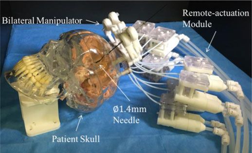
2518                                                                                      IEEE ROBOTICS AND AUTOMATION LETTERS, VOL. 3, NO. 3, JULY 2018

Fig. 3.   Key components and schematic diagram of a 1-DoF actuation design.

Fig. 4. (a) CAD model showing the key components of our bilateral stereotactic manipulators. (b) Lower layer of the manipulator positioned about 30mm above
the skull surface, which remains the sufficient space for ease of observation around the burr hole. (c) Overall dimensions observed, which demonstrates the design
is so compact that two (bilateral) manipulators attached on skull can be fully stretched in two extreme configurations within the confined space of a Siemens-style
mock head coil (inner diameter Ø265mm).

are also created to allow fixture of the sheath’s end for better                   at the housing base and needle tip, respectively. The cannula
tendon routing. The revolute joints inside the housing can be                      is connected by two passive joints Ju 5 and Jl5 from upper
therefore actuated by the tendons. Two ball joints (igus Inc.,                     and lower layers, respectively. Its pose can be manipulated by
Germany) are incorporated at the distal end of the forearms. A                     independent (X-Y) planar motion of the upper and lower layers
needle guide is oriented by these two joints, and axially fixed                    containing the points pu k and plk (k = 1, · · · , 5), respectively.
with the upper one. In prior to inserting the needle through the                   Such points denote the 2D coordinate of their corresponding
cannula held by both end-effectors of the double-layer manipu-                     joints Ju k and Jlk (k = 1, · · · , 5), which can be solved by the
lators, the allowable insertion depth is preset by the needle stop.                following equation sets:
Soft material is also embedded inside the cannula/needle stop
so as to limit the needle linear motion by inducing the sliding                                pu 3 − pu 5  = lf           pl3 − pl5  = lf
                                                                                                                     and                            (1)
friction.                                                                                      pu 4 − pu 5  = lf           pl4 − pl5  = lf

                                                                                      Horizontal offset a separating two actuated joints (i.e., Ju 1
D. Forward and Inverse Kinematics
                                                                                   and Ju 2 or Jl1 and Jl2 ) is 25 mm, while the vertical offset b of
  Fig. 5 depicts the kinematic diagram of one double-layer                         two layers is 16 mm. The array of actuated joint can be defined
manipulator. Two coordinate frames ΨO and ΨE are defined                           as q = [q1 , q2 , q3 , q4 ]T . Therefore, the angular ranges of active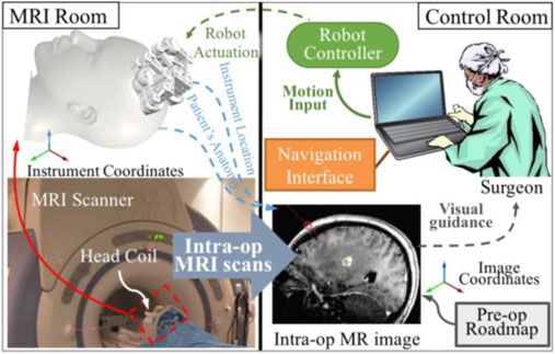
GUO et al.: COMPACT DESIGN OF A HYDRAULIC DRIVING ROBOT                                                                                               2519

                                                                            Fig. 6. Force-displacement diagram showing the transmission stiffness of the
                                                                            actuation module at four levels (0.5, 1, 1.5 and 2 bars) of pressure pre-loaded
                                                                            on the transmission liquid.

Fig. 5. Kinematic diagram of a single manipulator with coordinate frames
Ψ O and Ψ E defined at the housing base and the needle tip, respectively.   and ΔJu 2 Ju 4 Ju 5 :

                                                                                   lf2 = lu2 + pu 5 − pu 1 2 − 2lu pu 5 − pu 1  cosθu 1            (5)
joints Ju 1 , Jl1 are corresponding to q1 , q3 ∈ [29.7◦ , 195.3◦ ]; for
joints Ju 2 , Jl2 are q2 , q4 ∈ [−15.3◦ , 150.3◦ ]. The length of two              lf2 = lu2 + pu 2 − pu 5 2 − 2lu pu 2 − pu 5  cosθu 2            (6)
proximal links (upper arms) lu is 40 mm; for two distal links
(forearms) lf is 35 mm. Two types of singularities can be found                Angles ∠Ju 2 Ju 1 Ju 5 and ∠Ju 5 Ju 2 Ju 1 (denoted as αu 1 and
in this five-bar linkage mechanism [26]. The first type takes               αu 2 ) can be obtained similarly in triangle ΔJu 1 Ju 2 Ju 5 . To
place when forearms are collinear (e.g., joints Jl3 , Jl4 , Jl5 are         avoid the second type of singularity, joint Ju 3 , Ju 4 should
in one line), and the second one appears only when arms are                 be always positioned beyond triangle ΔJu 1 Ju 2 Ju 5 such that,
fully stretched. To prevent collineation of the pair of forearms,           q1 = θu 1 + αu 1 and q2 = π − (θu 2 + αu 2 ). The other actua-
a mechanical limit on the relative rotation is adopted. For in-             tion angles q3 , q4 can be solved based on the similar process.
stance, joint Jl5 will always locate outside quadrangle area of
Jl1 Jl2 Jl3 Jl4 . To resolve the forward kinematics, the needle’s                             III. EXPERIMENTS AND RESULTS

orientation can be denoted by the unit r as:
                                                                            A. Transmission Stiffness
                              pl5 − pu 5
                          r =                                        (2)       One of the primary factors which determines the system’s
                              pl5 − pu 5
                                                                            capability to resist external disturbance is the stiffness of the
   Assume the insertion depths, du and dl , are defined as the              hydraulic transmission presented. An iterative test was con-
linear distances from joints Ju 5 and Jl5 , respectively, to the            ducted on a 1-DoF actuation, i.e., from the master side to the
target. The position of needle tip pt , acting as the ultimate end          manipulator’s base joint. The upper arms of manipulator were
effector of both manipulators can be calculated:                            fixed such that rotation of the actuated joint was constrained
                         pt = pu 5 + d u · r

                                                                     (3)    properly. 10m long pipes filled with distilled water were used
                                                                            to connect both the master-and-slave hydraulic units. The mas-
   To find the four actuated joint angles q = [q1 , q2 , q3 , q4 ]T         ter unit was actuated by an electrical DC motor that provided
based on the desired needle pose w.r.t. the MR image coordi-                with 500 encoding pulses feedback. A torque sensor (HLT131,
nates, co-registration between the robot and image coordinate               Hualiteng Technology Co. Ltd., China) with 5 mNm sensitivity
system is required. Again, the planned parameters (i.e., pt and             was used to measure the external load. The tests were performed

r ) can be defined in ΨO . Coordinates pu 5 , pl5 can be found by           repeatedly (10 cycles) under the bi-directional load. The trans-
calculating the crossing points of needle and two layers using              mission fluid in the pipes was preloaded at 0.5, 1.0, 1.5 and
the line equations:                                                         2.0 bar in order to investigate the transmission stiffness vary-
                                                                          ing with different fluid pressure levels. The external loads were
            pu 5 = pt − du · r and pl5 = pt − dl · r                 (4)
                                                                            gradually increased, while recording the corresponding piston
   Note that coordinates pu 5 and pl5 belong to trian-                      displacements.
gle ΔJu 1 Ju 3 Ju 5 and ΔJl1 Jl3 Jl5 , respectively. Then, angle               The force-displacement diagram (Fig. 6) shows the increas-
∠Ju 3 Ju 1 Ju 5 and ∠Ju 4 Ju 2 Ju 5 (denoted as θu 1 , θu 2 ) can be        ing trend of transmission stiffness with higher fluid pressure
solved using cosine laws, respectively, in triangle ΔJu 1 Ju 3 Ju 5         pre-loaded. The data was linearly fitted using least-square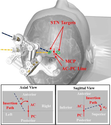
2520                                                                               IEEE ROBOTICS AND AUTOMATION LETTERS, VOL. 3, NO. 3, JULY 2018

                            TABLE I
                 NEEDLE TARGETING ACCURACY TEST

                        Needle tip              Normal to the needle

Accuracy (mm)        Left         Right          Left         Right
                 1.73 ± 0.75   1.21 ± 0.63   1.61 ± 0.72   1.15 ± 0.62

regression, which indicated the maximum stiffness coefficient
can reach 24.35 N/mm under 2bar pre-loaded pressure. The
interaction force between instrument and brain tissue is gener-
ally less than 0.8 N [5], [27]. It is indicated that the proposed
hydraulic transmission is stiff enough to transmit motion for
precise tissue manipulation. Compliance in the transmission
can be attributed to three major factors: i) stretching of the di-       Fig. 7.    System schematic of the MRI-guided robot-assisted stereotaxy.
aphragms, ii) deformation of the plastic structural components,                                          TABLE II
and iii) bulging in cross-sectional area of the pipes. To further in-                               MRI SCAN PARAMETERS
crease the transmission stiffness, components can be machined
by materials with higher rigidity, e.g., polyoxymethylene. Thus,                              w/o needle inserted   w/ needle inserted    SNR test
the minimal structural deformation under loading can be en-
                                                                            FOV (mm)              240 × 240             240 × 240        280 × 280
sured. Previous studies [18] have suggested shorter pipes can               Matrix                256 × 256             256 × 256        256 × 256
also contribute to higher stiffness, as well as lower fluid inertia         Acquisition            FSPGR                 FSPGR            T2-FSE
and friction.                                                               TR (ms)                 68.0                  68.0            2000.0
                                                                            TE (ms)                  2.8                   2.8             76.8
                                                                            Flip angle (°)           10                    10               90
B. Needle Targeting Accuracy
   An EM positional tracking system (Aurora, NDI Medical,
Canada) was used to measure the 3D coordinates of any point              passive tracking [28], [29], in which the real-time and automatic
defined in the experimental setup. Ten points were simulated as          localization cannot be made reliable due to their limited signal
the STN targets, five at each side on a plastic plate. They were         contrast to the background. The use of passive tracking could
roughly 100 mm below the lower-layer of manipulators, which              also be time-consuming as visualization of the markers takes
was a typical depth of stereotactic target beneath the human             place after 2D image reconstruction. The proposed wireless and
skull. These measured targets coordinates were registered with           miniaturized marker can act as an RF receiver to pick up the
the robot coordinate system. A phantom needle with similar               MR gradient signal along three principal scanning directions,
diameter (Ø1.4 mm) to a DBS cannula was used. A 6-DoF coil               as well as an inductor to resonate with the signal transmitted
sensor was fixed at the needle tip.                                      to the MRI scanner receiver [30]–[32]. Without the need for
   Configurations of the robot and needle guide, along with the          image reconstruction, they can be rapidly localized using 1D
needle insertion depth, were measured and calculated online.             projection techniques [13].
Once aiming at the target point, the needle was then inserted               The navigation test was carried out under MRI environment. It
manually. Such trial for each point was repeated 10 times. 100           simulated the conceptual system setup for MRI-guided robotic
trials were conducted in total. This targeting task was performed        stereotaxy, as in Fig. 7. To better simulate the surgical sce-
closely to the tracking system, and measurements were taken              nario, the robot was mounted on the skull model that would
when the 6-DoF sensor was at rest. These measurements were               be placed and scanned inside a head coil. To reveal the brain
repeated 500 times at each static location. The average of these         phantom in MR image, the “brain” was fabricated and made
500 measurements was used in the error analysis. Not only was            of agar gel (Biosharp Inc., China) to enhance the image con-
the proximal distance from needle tip to the target measured,            trast for needle targeting. The two films of MR coil circuits
but also the distance from the target to the needle axis. The            (1.5 × 5 × 0.2 mm3 ) are first employed to perform MR active
targeting accuracy was quantified by the mean error and its              tracking in 3D for robot control. Both were embedded in the
standard deviation (Table I). The error is generally less than           needle guide (Fig. 8(a)). 3D fast spoiled gradient recalled-echo
2 mm, and its variation also smaller than 1 mm. This accuracy is         (FSPGR) sequence was used to assess the location and orien-
comparable to the current stereotaxy practice [2]. Future work           tation of the needle guide. The sequence parameters are stated
in robot calibration and structural rigidity enhancement may             in Table II. A phantom needle made of carbon fiber was then
further improve this targeting performance.                              inserted and scanned with the same imaging sequence. Fig. 8(b)
                                                                         shows the resultant MR image in coronal view. Both the coils
                                                                         and the inserted needle can be visualized. The signal intensities
C. MR-Based Tracking Test
                                                                         of two coils are 1133.00 and 1341.00, in the high contrast to
   MR-based wireless tracking is first introduced to such robotic        those two circular areas comprising 59 pixels, which are sam-
stereotaxy. It possesses several advantages over the conventional        pled on the background and agar-gel brain, respectively, with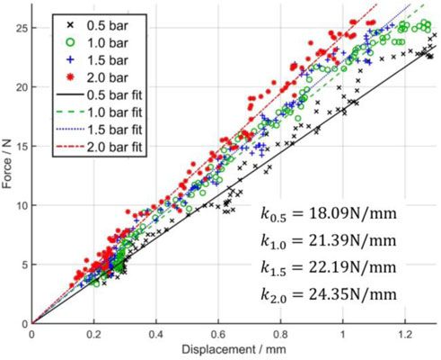
GUO et al.: COMPACT DESIGN OF A HYDRAULIC DRIVING ROBOT 2521
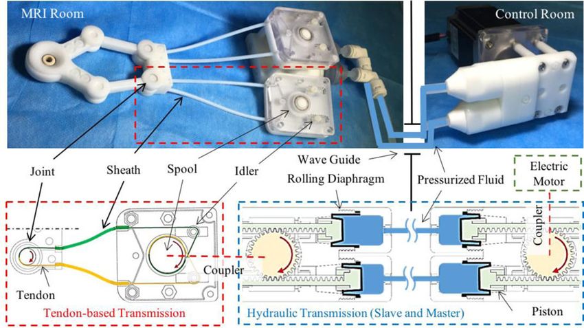
Fig. 8. (a) Needle guide embedded with two MR-based tracking coil units,
one of which is shown on its side wall. (b) MR image of the brain phantom (in the
coronal view) revealing the two tracking markers by the corresponding bright
spots. Dark straight line is the negative artifact of the needle. The two spots are
zoomed in (enclosed in the blue dash ellipse). Two red crosses probing at the
spots indicate the signal intensity of the coils, in contrast to those intensities
average within other two yellow circles: on the background and agar-gel brain Fig. 9. Upper: T2-weighted FSE images of an SNR phantom. These images
phantom. (c) Virtual configurations of the instrument augmented on those high- were generated at different stages of robot operation. A binary map for FSE
contrast markers, which is posed above the 3D reconstructed brain phantom. sequence marked the actifacts as white pixels. No artifact was observed within
Any change of the instrument pose could be detected continuously (at 30-40Hz) the phantom area. As defined by the ASTM standard, it indicated zero artifact
under the real-time MR-tracking sequence. was created by the operation of robot. Lower: SNR test results. The existence
or operation of the proposed robot is demonstrated to have minimal influence
to SNR.
average signal intensities of 116.27 and 232.05. This contrast
can be further enhanced by dedicated excitation at lower flip images corresponding to the two conditions, baseline and robot
angles (e.g., 1°), which can minimize the background signals. operating, were compared. Pixels with intensity that varied by
At a distance of 48 mm from the isocenter, the maximum er- 30% or above were considered as artifacts [35]. These artifacts
ror in marker position was 0.50 mm with inherent precision of would appear as white pixels in the binary map (FSE Artifact,
0.12 mm. This deviation can be increased when the marker is Fig. 9). No artifact is observed within the phantom area. As de-
further from the isocenter due to the nonlinearities of gradient fined by the ASTM standard, it indicates the operation of robot
fields. generated zero artifact.
D. MRI-Compatibility Test IV. CONCLUSION
The MRI-compatibility test was conducted in a 1.5T MRI In this letter, we present the design of an MRI-guided robot
scanner (SIGNA HDxt, GE Healthcare, USA) at a room tem- for stereotactic neurosurgery. Not only is the robot capable to
perature of around 20°C. A square SNR phantom (Part Number: perform bilateral targeting of both STNs independently, but also
150027, USA Instruments, Inc.) for GE MRI was placed at the it is compact in size so as to operate within the confined space
isocenter of the scanner. A baseline image without the presence of a regular MRI head coil. High-performance hydraulic trans-
of robot was acquired using T2-weighted fast spin echo (FSE) missions are incorporated. Maximum stiffness coefficient of
sequence (Table II). This is the acquisition sequence commonly 24.35 N/mm can be achieved. A needle insertion task of DBS
used for localization in stereotactic neurosurgery. Upon intro- has also been simulated, in which our experimental results show
ducing the robot right beside the phantom, MR images were ob- the targeting accuracy more sufficient than the standard surgical
tained under three different robot operating conditions (Fig. 9), requirement.
which were: i) Static: robot was introduced and remained pow- The navigation test has been conducted under MRI settings.
ered off; ii) Powered: robot remained still, but the hydraulic and Advanced MR-based wireless tracking is newly developed and
electric power was on; iii) Operating: robot was in full opera- incorporated into this robot. Two tracking units are fabricated
tion. Referring to the guidelines provided by National Electrical and embedded inside the instrument guide, marking two very
Manufacturer’s Association (NEMA) [33], the signal-to-noise high-contrast bright spots in the image domain. Such marker
ratios (SNR) in MR images were evaluated. As the results shown intensities appear about 10 times of the imaging background and
(Fig. 9), SNR loss is within 3% even with the robot in full mo- 5 times of the agar-gel brain phantom, thus enabling the accurate
tion. MR image artifacts caused by the presence of robot were and easy instrument localization. It is worth noting that the
quantified based on the ASTM standard test method [34]. The presented MR-tracking approach could enable a continuous and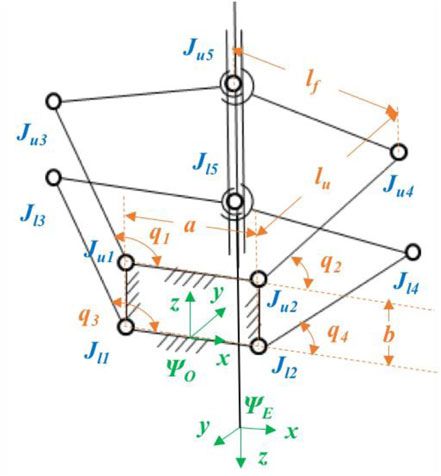
2522                                                                                      IEEE ROBOTICS AND AUTOMATION LETTERS, VOL. 3, NO. 3, JULY 2018

real-time positional feedback at 30 40 Hz using the proper MR                      [12] G. Widmann, “Image-guided surgery and medical robotics in the cranial
tracking sequences, thus outperforming the use of many passive                          area,” Biomed. Imag. Intervention J., vol. 3, no. 1, 2007.
                                                                                   [13] F. Galassi, D. Brujic, M. Rea, N. Lambert, N. Desouza, and M. Ristic,
fiducials only detected using imaging sequence ones. Moreover,                          “Fast and accurate localization of multiple RF markers for tracking in
compared to the MR-based active tracking, this wireless one                             MRI-guided interventions,” Magn.Reson. Mater. Phys. Biol. Med., vol. 28,
does not require any cable connection with the scanner receivers.                       pp. 33–48, 2015.
                                                                                   [14] Z. Guo, Z. Dong, K.-H. Lee, H. C. Fu, C. L. Cheung, and K.-W. Kwok,
This avoids many technical complications in wiring the co-axial                         “Robotic stereotactic system for MRI-guided neurosurgery,” U.S. Patent
cables with the tracking units as well. MRI-compatibility test                          62/623280, 2018.
shows the minimal imaging interference is generated even when                      [15] P. S. Larson, P. A. Starr, G. Bates, L. Tansey, R. M. Richardson, and A.
                                                                                        J. Martin, “An optimized system for interventional magnetic resonance
the robot is in full operation.                                                         imaging-guided stereotactic surgery: Preliminary evaluation of targeting
   In stereotactic neurosurgery, the accuracy of instrument place-                      accuracy,” Operative Neurosurg., vol. 70, pp. 95–103, 2011.
ment can be greatly enhanced by coping with brain shift refer-                     [16] D. Tarsy, J. L. Vitek, and A. M. Lozano, Surgical Treatment of Parkinson’s
                                                                                        Disease and Other Movement Disorders. Berlin, Germany: Springer, 2002.
ring to the brain map continuously updated with the intra-op                       [17] Standard Practice for Marking Medical Devices and Other Items for Safety
MRI. This brain shift effect could be minimal with this bilat-                          in the Magnetic Resonance Environment, ASTM Int., West Conshohocken,
eral approach without having to create extra anchorage site on                          PA, USA, Standard ASTM F2503-13, 2013.
                                                                                   [18] G. Ganesh, R. Gassert, E. Burdet, and H. Bleuler, “Dynamics and control
skull. This development of MR safe robotic system, along with                           of an MRI compatible master-slave system with hydrostatic transmission,”
the MR-tracking, is timely while taking advantages of current                           in Proc. IEEE Int. Conf. Robot. Autom., 2004, pp. 1288–1294.
advances of fast MR imaging/tracking sequences. Direct visu-                       [19] D. B. Comber, E. J. Barth, and R. J. Webster, “Design and control of
                                                                                        an magnetic resonance compatible precision pneumatic active cannula
alization of surgical targets based on this tele-manipulation of                        robot,” J. Med. Devices, vol. 8, 2014, Art. no. 011003.
the instrument in situ under MRI may prevent the risks from                        [20] Z. Guo, T. Lun, Y. Chen, H. Su, D. Chan, and K. Kwok, “Novel design of an
damaging the critical brain structures. This would also avoid                           MR-safe pneumatic stepper motor for MRI-guided robotic interventions,”
                                                                                        in Proc. 9th Hamlyn Symp. Med. Robot., 2016, pp. 50–51.
the complications of local anesthesia, thus adding confidence                      [21] Y. Chen, K.-W. Kwok, and Z. T. H. Tse, “An MR-conditional high-torque
by having the post-procedural evaluations of surgical outcome                           pneumatic stepper motor for MRI-guided and robot-assisted intervention,”
based on images, instead of verbal/physical interaction with                            Ann. Biomed. Eng., vol. 42, pp. 1823–1833, 2014.
                                                                                   [22] J. P. Whitney, T. Chen, J. Mars, and J. K. Hodgins, “A hybrid hydrostatic
the awake patient during the procedure in many current prac-                            transmission and human-safe haptic telepresence robot,” in Proc. IEEE
tices. Finally, it is expected to greatly save the operation time                       Int. Conf. Robot. Autom., 2016, pp. 690–695.
from the repeated instrument placement/adjustment, as well as                      [23] K. H. Lee et al., “MR safe robotic manipulator for MRI-guided intra-
                                                                                        cardiac catheterization,” IEEE/ASME Trans. Mechatronics, 2018.
the image alignment with head frame. The overall healthcare                        [24] J.-P. Merlet, “Parallel robots: Open problems,” in Robotics Research. New
expenditure could be significantly reduced, also compensating                           York, NY, USA: Springer, 2000, pp. 27–32.
the high cost of using MRI.                                                        [25] L. Campos, F. Bourbonnais, I. A. Bonev, and P. Bigras, “Development of
                                                                                        a five-bar parallel robot with large workspace,” in Proc. ASME 2010 Int.
                                                                                        Design Eng. Tech. Conf. Comput. Inf. Eng. Conf., 2010, pp. 15–18.
                                  REFERENCES                                       [26] A. Figielski, I. A. Bonev, and P. Bigras, “Towards development of a 2-
                                                                                        DOF planar oparallel robot with optimal workspace use,” in Proc. IEEE
 [1] R. M. deSouza, E. Moro, A. E. Lang, and A. H. Schapira, “Timing of                 Int. Conf. Syst. Man Cybern., 2007, pp. 1562–1566.
     deep brain stimulation in Parkinson disease: A need for reappraisal,” Ann.    [27] Ö. Bebek, M. J. Hwang, and M. C. Cavusoglu, “Design of a parallel robot
     Neurol., vol. 73, pp. 565–575, 2013.                                               for needle-based interventions on small animals,” IEEE/ASME Trans.
 [2] R. A. Vega, K. L. Holloway, and P. S. Larson, “Image-guided deep brain             Mechatronics, vol. 18, no. 1, pp. 62–73, Feb. 2013.
     stimulation,” Neurosurg. Clin., vol. 25, pp. 159–172, 2014.                   [28] H. Busse, R. Trampel, W. Gründer, M. Moche, and T. Kahn, “Method
 [3] C. Nimsky, O. Ganslandt, P. Hastreiter, and R. Fahlbusch, “Intraoperative          for automatic localization of MR-visible markers using morphological
     compensation for brain shift,” Surg. Neurol., vol. 56, pp. 357–364, 2001.          image processing and conventional pulse sequences: Feasibility for image-
 [4] C. Sidiropoulos et al., “Intraoperative MRI for deep brain stimulation lead        guided procedures,” J. Magn. Reson. Imag., vol. 26, pp. 1087–1096, 2007.
     placement in Parkinson’s disease: 1 year motor and neuropsychological         [29] Y. Chen et al., “Design and fabrication of MR-tracked metallic stylet for
     outcomes,” J. Neurol., vol. 263, pp. 1226–1231, 2016.                              gynecologic brachytherapy,” IEEE/ASME Trans. Mechatronics, vol. 21,
 [5] G. R. Sutherland, Y. Maddahi, L. S. Gan, S. Lama, and K. Zareinia,                 no. 2, pp. 956–962, Apr. 2016.
     “Robotics in the neurosurgical treatment of glioma,” Surg. Neurol. Int.,      [30] M. A. Rube, A. B. Holbrook, B. F. Cox, J. G. Houston, and A.
     vol. 6, (Suppl 1): S1, 2015.                                                       Melzer, “Wireless MR tracking of interventional devices using phase-
 [6] J. W. Motkoski and G. R. Sutherland, “Why robots entered neurosurgery,”            field dithering and projection reconstruction,” Magn. Reson. Imag., vol. 32,
     Exp. Neurosurg. Animal Models, vol. 116, pp. 85–105, 2016.                         pp. 693–701, 2014.
 [7] M. J. LaRiviere and R. E. Gross, “Stereotactic laser ablation for medically   [31] M. B. Ooi, M. Aksoy, J. Maclaren, R. D. Watkins, and R. Bammer,
     intractable epilepsy: The next generation of minimally invasive epilepsy           “Prospective motion correction using inductively coupled wireless RF
     surgery,” Frontiers Surg., vol. 3, no. 64, 2016.                                   coils,” Magn. Reson. Med., vol. 70, pp. 639–647, 2013.
 [8] A. H. Hawasli, W. Z. Ray, R. K. Murphy, R. G. Dacey Jr, and E. C.             [32] Z. Guo, Z. Dong, K.-H. Lee, C. L. Cheung, K. C. D. FU, and K. W. Kwok,
     Leuthardt, “Magnetic resonance imaging-guided focused laser interstitial           “Robotic catheter system for MRI-guided cardiovascular interventions,”
     thermal therapy for subinsular metastatic adenocarcinoma: Technical case           U.S. Patent 15/630 406; PCT/CN 2017/089 701, 2017.
     report,” Oper. Neurosurg., vol. 70, pp.332–337, 2011.                         [33] Determination of Signal-To-Noise Ratio (SNR) in Diagnostic Magnetic
 [9] W. Wang et al., “Real-time active MR-tracking of metallic stylets in MR-           Resonance Images, Nat. Elect. Manuf. Assoc., Rosslyn, VI, USA, NEMA
     guided radiation therapy,” Magn. Reson. Med., vol. 73, pp. 1803–1811,              MS 1-2008 (R2014), 2008.
     2015.                                                                         [34] Standard Test Method for Evaluation of MR Image Artifacts From Passive
[10] C. J. Nycz et al., “Mechanical validation of an MRI compatible stereo-             Implants ASTM Int., West Conshohocken, PA, USA, ASTM F2119-07,
     tactic neurosurgery robot in preparation for pre-clinical trials,” in Proc.        2006.
     IEEE/RSJ Int. Conf. Intell. Robots Syst., 2017, pp. 1677–1684.                [35] M. A. Tavallaei, M. Lavdas, D. Gelman, and M. Drangova, “Magnetic
[11] F. W. Petraglia et al., “Comparison of bilateral vs. staged unilateral deep        resonance imaging compatible remote catheter navigation system with
     brain stimulation (DBS) in Parkinson’s disease in patients under 70 years          3 degrees of freedom,” Int. J. Comput. Assisted Radiol. Surg., vol. 11,
     of age,” Neuromodulation, Technol. Neural Interface, vol. 19, pp. 31–37,           pp. 1537–1545, 2016.
     2016.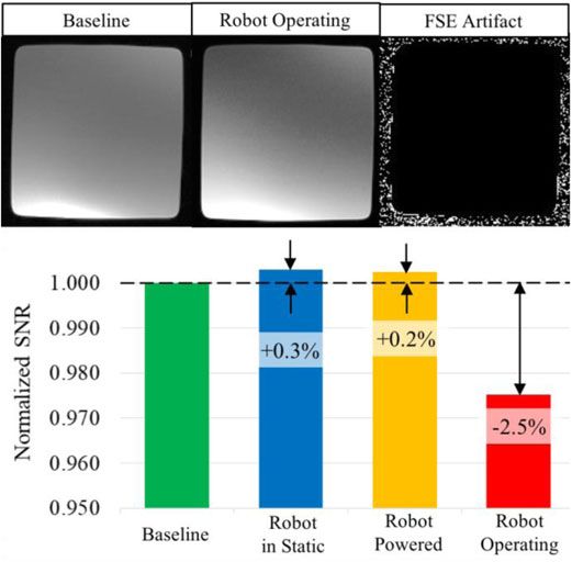
You can also read