Conventional Automatic Fire Detectors - FCP 320/FCH 320 - en
←
→
Page content transcription
If your browser does not render page correctly, please read the page content below
Conventional Automatic Fire Detectors
FCP‑320/FCH‑320

en    User manual

Conventional Automatic Fire Detectors                                          Table of contents | en   3

Table of contents
1                     Product Description                                                                5
2                     System Overview                                                                    6
2.1                   Configuration of the Detector                                                      6
2.2                   Functional Description of Sensor Technology                                        6
2.2.1                 Optical Sensor (Smoke Detector)                                                    6
2.2.2                 Thermal Sensor (Heat Detector)                                                     6
2.2.3                 Chemical Sensor (Gas Sensor)                                                       6
2.3                   System Description                                                                 6
2.4                   Features                                                                           7
3                     Planning                                                                           8
3.1                   Basic Planning Guidelines                                                          8
3.2                   Use in Fire Barriers Conforming to DIBt                                            8
4                     Installation                                                                       9
4.1                   Overview of Detector Bases                                                         9
4.2                   Overview of Detector Base Sounder                                                 10
4.3                   Mounting the Bases                                                                10
4.4                   Wiring                                                                            11
4.4.1                 Wiring MS 400/MS 400 B                                                            12
4.4.2                 Wiring MSR 320                                                                    13
4.4.3                 Wiring MSS 300                                                                    14
4.5                   Installing the Detector Head                                                      14
4.6                   Detector Removal                                                                  15
5                     Accessories                                                                       16
5.1                   EOL Module for Line Termination According to EN 54-13                             16
5.2                   Support Plates for Detector Identification                                        16
5.3                   SK 400 Protective Basket                                                          16
5.4                   SSK 400 Protective Dust Cover                                                     17
5.5                   WA400 Detector Console                                                            17
5.6                   MH 400 Detector Heating Element                                                   17
5.7                   Remote Indicators                                                                 17
6                     Order Overview                                                                    22
6.1                   Detector Variants                                                                 22
6.1.1                 Detectors with 820 Ohm Alarm Resistor                                             22
6.1.2                 Detectors with 470 Ohm Alarm Resistor*                                            22
6.2                   Detector Bases                                                                    22
6.3                   Detector Accessories                                                              22
6.4                   Installation Accessories                                                          23
6.5                   Detector Base Sounders                                                            23
6.6                   Remote Indicators                                                                 23
6.7                   Service Accessories                                                               23
7                     Maintenance and Service                                                           25
7.1                   Coding of the Detector Types                                                      26
7.2                   Test Procedure for Detectors with C-Sensor                                        26
7.3                   Test Procedure for Detectors without C-Sensor                                     27
7.4                   Warranty                                                                          27
7.5                   Repair                                                                            27
7.6                   Disposal                                                                          27
7.7                   Additional Documentation                                                          27

Bosch Sicherheitssysteme GmbH                             User manual         2022-01 | 12 | F.01U.004.377
4    en | Table of contents                          Conventional Automatic Fire Detectors

8                     Specifications                                                   28
9                     Abbreviations                                                    31

2022-01 | 12 | F.01U.004.377           User manual        Bosch Sicherheitssysteme GmbH

Conventional Automatic Fire Detectors Product Description | en 5
1 Product Description
Notice!
i This Product Information describes the entire product range of the FCP-320/FCH-320
Conventional Automatic Fire Detectors.
The FCP-320/FCH-320 Conventional Automatic Fire Detectors works on the basis of the
conventional technology and combines standard detection methods such as scattered light
measurement and temperature measurement with gas measuring technology at the highest
configuration level.
This method uses state-of-the-art processing methods to evaluate the signals from the gas
sensor and scattered light sensor or thermal sensor.
Security against false alarms is thus increased significantly and detection time is reduced in
comparison with the fire detectors generally available on the market today.
Thanks to the higher information content of the multisensor detectors, the use of detectors is
possible in environments where pure smoke detectors cannot be used.
The detectors are available in the following configuration levels:
– FCP-OC320: Combined optical, gas-sensitive smoke detectors
– FCP-OT320: Combined optical, thermal smoke detectors
– FCP-O320: Optical smoke detectors
– FCH-T320: Thermal detectors.
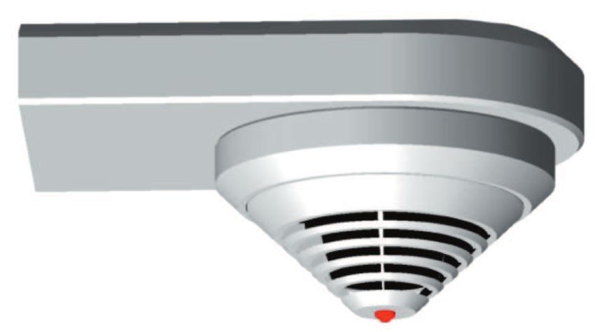
The detector's timeless and innovative design is a result of the cooperation between engineers
and designers. With this design it is possible to reconcile the contradictory goals of a
generous installation space and a small detector.
The placement of the individual display on the detector tip is the first externally visible
characteristic of the installation-friendly development concept. The stable and robust detector
base need no longer be aligned due to the position-independent position of the individual
display.
It is suitable for surface and flush cable mounting and includes separate mounting points for
dropped ceiling and concealed sockets. In addition, it fits all common bore patterns. For
surface mounting, the cable may be fed through on the side.
The integrated strain relief for interfloor cables prevents the removal of cables from the
terminal after installation. The terminals are easily accessible; a retainer for the end of line
resistor is integrated. Cable diameters of up to 2.5 mm2 can be used.
It can be equipped with a damp room seal so that all installation requirements can be covered
with one base.
The 320 Series detectors are available with either a 470 Ω alarm resistor or a 820 Ω alarm
resistor. The operating voltage range is 8.5 V DC to 30 V DC, which allows the detectors to be
used with almost every common conventional fire panel.
Bosch Sicherheitssysteme GmbH User manual 2022-01 | 12 | F.01U.004.377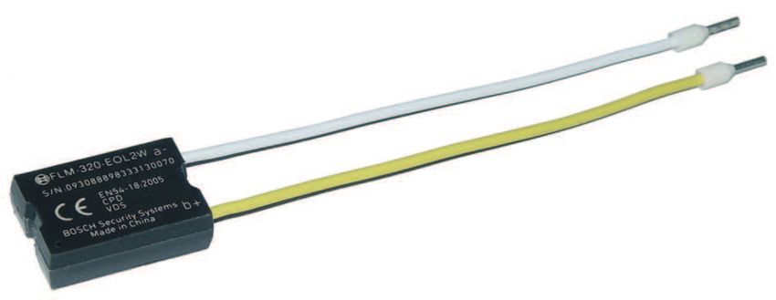
6     en | System Overview                                                            Conventional Automatic Fire Detectors

2                     System Overview
2.1                   Configuration of the Detector
                      1        Smoke measurement chamber with                     4                              3
                               optical sensor

                      2        Thermal sensor                            2

                      3        Chemical sensor (covered on the cross-                                                 1
                               section)

                      4        Individual display

                      5        PC board with evaluation electronics                                 6
                                                                              5
                      6        Detector base
                                                                        Configuration of the Detector

2.2                   Functional Description of Sensor Technology
2.2.1                 Optical Sensor (Smoke Detector)
                      The optical sensor uses the scattered-light method.
                      An LED sends light into the measuring chamber (item 1); this light is absorbed by the labyrinth
                      structure. In the event of a fire, smoke enters the measuring chamber. The light is scattered by
                      the smoke particles and hits the photo diodes, which transform the quantity of light into a
                      proportional electrical signal.

2.2.2                 Thermal Sensor (Heat Detector)
                      A thermistor (item 2) in a resistance network is used as a thermal sensor; an analog-digital
                      converter measures the temperature-dependent voltage at regular intervals.
                      The temperature sensor switches to an alarm state if the maximum temperature exceeds
                      54 °C (thermal maximum) or if there is a defined temperature increase within a particular
                      timeframe (thermal differential).

2.2.3                 Chemical Sensor (Gas Sensor)
                      The gas sensor (item 3) detects mainly the carbon monoxide
                      (CO) that is produced by a fire, but it also detects hydrogen
                      (H) and nitrogen monoxide (NO).
                      The underlying measurement principle is CO oxidation and the
                      measurable current that it creates. The sensor signal value is
                      proportional to the concentration of gas.                                                 3
                      The gas sensor supplies additional information in order to
                      reliably suppress deception variables.
                                                                                        Chemical Sensor

2.3                   System Description
                      Up to two detection principles are integrated into the FCP-320/FCH-320 Series Fire Detectors:
                      –      Optical (for smoke): O
                      –      Thermal (for heat): T
                      –      Chemical (for gas): C

2022-01 | 12 | F.01U.004.377                            User manual                        Bosch Sicherheitssysteme GmbH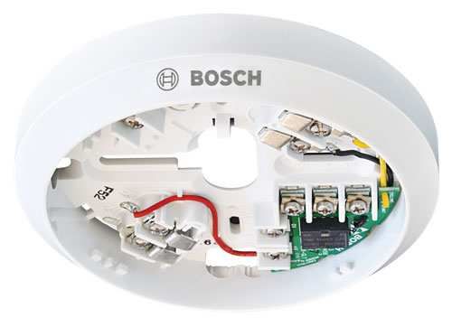
Conventional Automatic Fire Detectors                                                            System Overview | en    7

                      All sensor signals are analyzed continually by the internal signal analysis electronics and are
                      linked with each other. If a signal combination fits the detector’s programmed code field, an
                      alarm is automatically triggered.
                      By linking the sensors (combined detectors), the detector can also be used in places where
                      the work carried out gives rise to light smoke, steam or dust.
                      The FCP-OC320/FCP-OC320-R470 detectors analyze the present CO concentration and adjust
                      the threshold of the optical sensor in accordance with the CO concentration. If no CO is in the
                      air, the alarm is triggered nonetheless at a certain level of smoke density and above. However,
                      the alarm is not triggered if only CO is detected in the air.
                      The FCP-OT320/FCP-OT320-R470 detectors trigger an alarm in the case of smoke as well as in
                      the case of a temperature rise. Additionally, the threshold of the optical sensor is adjusted in
                      accordance with the absolute temperature and the rate of temperature rise.

2.4                   Features
                      –    Active adjustment of the threshold (drift compensation) if the optical sensor becomes
                           contaminated.
                      –    Active adjustment of the threshold (drift compensation) of the chemical sensor.
                      –    Activation of a remote external detector alarm display is possible.
                      –    Optional mechanical removal safeguard (can be activated/deactivated).
                      –    Dust-resistant labyrinth and cap construction.
                      –    Every detector has a “Chamber Maid Plug” (a cleaning opening with a plug) for blowing
                           out the optical chamber with compressed air (not required for the FCH‑T 320/
                           FCH‑T 320‑R470/FCH‑T 320‑FSA Heat Detectors).
                      –    Connectable to Bosch fire panels and the majority of conventional fire panels available on
                           the market.
                      –    Two variants with 820 Ω alarm resistor and 470 Ω alarm resistor enables the detector
                           application with nearly all conventional fire panels.
                      –    An unshielded cable may be used for the primary line.

Bosch Sicherheitssysteme GmbH                          User manual                           2022-01 | 12 | F.01U.004.377
8     en | Planning                                                                Conventional Automatic Fire Detectors

3                     Planning
                       Notice!

      i                FCP-320/FCH-320 Conventional Automatic Fire Detectors are not designed for exterior use.

3.1                   Basic Planning Guidelines
                      –    The planning of multisensor fire detectors takes place according to the guidelines for
                           optical detectors, until an independent guideline has been worked out with the VdS (see
                           DIN VDE 0833 Part 2 and VDS 2095):
                           –     Maximum monitoring area 120 m2
                           –     Maximum installation height 16 m.
                      –    Maximum permitted air speed: 20 m/s.
                      –    A maximum of 32 detectors can be connected per primary line. This number is limited to
                           20 detectors when connected to an UGM 2020 (GIF/GIF2).

3.2                   Use in Fire Barriers Conforming to DIBt
                      The FCH‑T320‑FSA and FCP-O320 are available for use in fire barriers conforming to the
                      guideline of the DIBt (Deutsches Institut für Bautechnik/German Institute for Building
                      Technology).
                      When planning for fire barriers conforming to DIBt, the FCH-T 320‑FSA detector has already
                      been set to category A1R.
                      Both models have DIBt approval.

2022-01 | 12 | F.01U.004.377                          User manual                       Bosch Sicherheitssysteme GmbH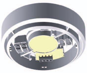
Conventional Automatic Fire Detectors Installation | en 9
4 Installation
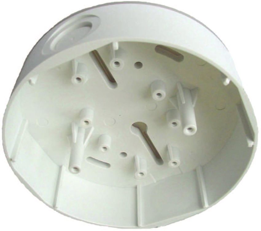
4.1 Overview of Detector Bases
The FCP-320/FCH-320 Series detector head is used in one of the following listed detector
bases, which are suitable for both flush-mounted and surface-mounted cable feed. They have
separate attachment points for ceiling mount/flush-mounted back boxes. In addition, they fit
all standard bore patterns.
The detector bases are made from white ABS plastic (color similar to RAL 9010) and have a
matte surface finish.
The bases have screw terminals for connection of the detector and its accessories to the fire
panel. Contacts connected with the terminals provide for a secure electrical connection when
mounting the FCP-320/FCH-320 detector heads. Cables up to 2.5 mm2 can be used.
To protect against unauthorized removal, the detector head can be secured with a variable
locking.
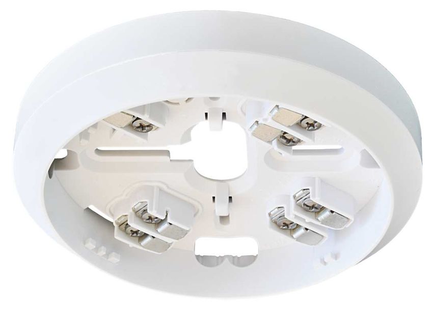
MS 400
The MS 400 Detector Base is the standard detecor base. It has
seven screw terminals.
MS 400 B
The standard MS 400 Detector Base with Bosch-branding.
FAA-420-SEAL
Seal for using the MS 400 and MS 400 B detectors in a humid
environment. The TPE seal protects the detector reliably against
the penetration of condensed water.
MSR 320
The MSR 320 Conventional Detector Base with Relay is provided
with an integrated relay that has NO/C/NC contacts for switching
applications (e. g. non EN-54 third party applications, dampers,
door holders, etc.).
Bosch Sicherheitssysteme GmbH User manual 2022-01 | 12 | F.01U.004.377
10    en | Installation                                                                Conventional Automatic Fire Detectors

                          MSC 420
                          The MSC 420 Additional Base was designed specially for surface
                          mounted cable feed via cable protection conduits. It is used in
                          combination with any of the above listed bases. It has two
                          opposing pre-cut inlets of 20 mm diameter and two additional
                          opposing and prepared inlets for up to 28 mm diameter.
                          The additional base has a diameter of 120 mm and a height of
                          36.7 mm.
                          To protect against condensed water penetration, a seal made of
                          TPE is situated on the base of the MSC 420.

4.2                       Overview of Detector Base Sounder
                          Detector base sounders are used if the acoustic signaling of an alarm is required directly at
                          the location of the fire.

                          –    MSS 300 Base sounder white, for conventional
                               technology, connection via the detector C point.
                          –    MSS 300 WH-EC Base Sounder, white for conventional
                               technology, with external activation.
                          The integrated tone generator has 11 tones for selection (incl.
                          tones according to DIN 33404 and EN 457) with sound
                          pressure of max. 100 dBA, depending on the type of tone
                          selected.
                          The tone type on conventional variants is set via four DIP
                          switches and the volume adjusted continuously via a
                          potentiometer.
                          Surface mounted and flush mounted cable feed are possible.

4.3                       Mounting the Bases
                          The detector bases are screwed to the even, dry surface using two screws approx. 55 mm
                          apart.
                          In the case of cable feed for surface mounting, break out the prepared entry points (X) on the
                          housing.
                          In the case of flush mounted cable feed, route the cable through the opening in the centre of
                          the base.
                          The short mounting bores marked in the sketch with “Y” may be used only for fixing over a
                          back box.

                          Notice!

      i                   Cable feed and outfeed can be on the same side.
                          For cable feed at the FAA-420-SEAL and MSC 420 puncture the sealing with a pointed tool.
                          Do not cut the sealing with a knife.

2022-01 | 12 | F.01U.004.377                              User manual                       Bosch Sicherheitssysteme GmbH
Conventional Automatic Fire Detectors Installation | en 11
Ø 120
X
14
22.7
7.8
Ø 100
55
Y
Y
4.4 Wiring
Notice!
i Keep screening wire as short as possible and insulate it.
Bosch Sicherheitssysteme GmbH User manual 2022-01 | 12 | F.01U.004.37712 en | Installation Conventional Automatic Fire Detectors
4.4.1 Wiring MS 400/MS 400 B
b1
b2 } LSN +/L..b
max. 30 V DC
bk ye
ye
wh rd
bk gn
a1/a2
(LSN -/L..a)
C
bk rd
– +
max. 3m
FAA-420-RI
ye yellow, connects to b1/b2 + / L..b (conventional)
wh white, connects to a1/a2 - / L..a (conventional)
rd red, connects to +V
bk black, connects to 0V
gn green, connects to shielding wire
c Indicator output
+V / 0V Terminals for looping through the power supply to subsequent elements
FAA-420-RI Remote Indicator
Notice!
i When using unshielded cables for the connection of the remote indicator, the maximum cable
length is 3m. No limitation when using shielded cables.
2022-01 | 12 | F.01U.004.377 User manual Bosch Sicherheitssysteme GmbHConventional Automatic Fire Detectors Installation | en 13
4.4.2 Wiring MSR 320
Maximum contact load (resistive load) of the change-over relay:
– 62.5 VA: 0.5 A at 125 V AC
– 30 W: 1 A at 30 V DC
0,5 A / 125 V AC
1 A / 30 V DC
NC NO
COM
b2
V+
b1
NC C NO
ye ye
wh
c gn
C
a1 | a2
V–
ye yellow, connects to b1/b2 V+
wh white, connects to a1/a2 V-
gn green, connects to shielding wire
NC / C / NO Changeover relay (for the MSR 320 only)
Bosch Sicherheitssysteme GmbH User manual 2022-01 | 12 | F.01U.004.37714 en | Installation Conventional Automatic Fire Detectors
4.4.3 Wiring MSS 300
red black blue
red black blue
b2
b1
c a1/
a2
MSS 300
a1 / a2 L . . . a (conventional) / LSN -
b1 , b2 L . . . b (conventional) / LSN +
C Remote indicator output
screen wire (has to be isolated and as short as possible)
red 24V DC power supply for the first and the second tone.
black for activating the first tone.
blue for activating the second tone.
4.5 Installing the Detector Head
Notice!
i The packaging for the multisensor detector with C sensor consists of tear-proof PE-ALU
laminated film and must be cut open carefully.
After installation and connection of the base, the detector head is set into the base and turned
to the right as far as it will go.
Detector bases are delivered with inactive locks.
The detector head can be locked into the base (removal protection). The locking feature is
activated by breaking the bolt (X) out of the base and pushing it into the corresponding guide,
as shown in , page 14.
2022-01 | 12 | F.01U.004.377 User manual Bosch Sicherheitssysteme GmbHConventional Automatic Fire Detectors Installation | en 15
1 2 3
X
X
X X
Figure 4.1: Activating the Removal Protection
1 Bolt (X) prior to breaking out
2 Bolt (X) installed but inactive
3 Locking activated
4.6 Detector Removal
Unlocked detector heads are disassembled by turning them to the left and removing them
from the base.
Locked detector heads are disassembled by inserting a screwdriver into the unlocking opening
(Y) so that the bolt is pushed upward; at the same time, the detector head should be turned
to the left.
Y
Figure 4.2: Detector Removal (Locked Detector)
Bosch Sicherheitssysteme GmbH User manual 2022-01 | 12 | F.01U.004.37716 en | Accessories Conventional Automatic Fire Detectors
5 Accessories
5.1 EOL Module for Line Termination According to EN 54-13
FLM-320-EOL2W EOL-Module
The FLM-320-EOL2W EOL module is a 2-wire module for
terminating a conventional line.
It detects faults in the line and transmits a notification to the
fire panel display.
For a conventional connection one line must not contain
more than 32 automatic detectors.
5.2 Support Plates for Detector Identification
The support plates are made from 1.8mm thick ABS plastic and are clamped between the
detector base and the ceiling.
TP4 400 Support Plate
The TP4 400 Support Plate is intended for an installation
height up to 4 m and is designed for labels up to a size of
approximately 65 x 34 mm.
15 / 4
TP8 400 Support Plate
The TP8 400 Support Plate is intended for an installation
height up to 8 m and is designed for labels up to a size of
approximately 97 x 44 mm.
5.3 SK 400 Protective Basket
The SK 400 Protective Basket is installed over the detector
and gives the detector substantial protection against
damage.
If the detector is mounted in a sports facility, for example,
the protective basket prevents balls or other sports
equipment from hitting the detector and damaging it.
2022-01 | 12 | F.01U.004.377 User manual Bosch Sicherheitssysteme GmbHConventional Automatic Fire Detectors Accessories | en 17
5.4 SSK 400 Protective Dust Cover
The SSK 400 Protective Dust Cover is necessary during
construction work to protect an installed detector base,
with or without upper detector section, from contamination.
The protective dust cover made from polypropylene (PP) is
pushed onto the installed detector base.
5.5 WA400 Detector Console
The WA400 Detector Console is used to install detectors
above door frames or similar in compliance with DIBt.
The console is supplied with a pre-mounted MS 400
Detector Base (the detector shown is not included in the
scope of delivery).
5.6 MH 400 Detector Heating Element
The MH 400 Detector Heating Element is required if the
detector is used in an environment where water
condensation can occur, such as in a warehouse that must
frequently be opened briefly for delivery vehicles.
The detector heating element is connected to the + V/0 V
terminals in the detector base.
Operating voltage: 24 V DC
Resistor: 1 kΩ
Maximum power dissipation: 3 W.
The heating is supplied with power either by the looped-
through supply voltage via the control panel or by a separate
power supply unit.
With supply via the control panel, the number of detector
heating elements depends on the cable cross section and
cable length used.
5.7 Remote Indicators
A Remote Indicator is required if the detector is not directly visible or has been mounted in
false ceilings or floors.
The remote indicators should be installed in corridors or access pathways to the
corresponding building sections or rooms.
Wiring
For connection to the standard bases MS400/MS400B note the following:
Notice!
i When using unshielded cables for the connection of the remote indicator, the maximum cable
length is 3m. No limitation when using shielded cables.
Bosch Sicherheitssysteme GmbH User manual 2022-01 | 12 | F.01U.004.37718 en | Accessories Conventional Automatic Fire Detectors
FAA‑420‑RI‑ROW
1. Wire the remote indicator as shown.
2. Place the cap on the base plate in such a way that the two hooks are inserted into the
slits.
3. Press the cap lightly onto the base plate until the snap‑fit‑hook engages.
FAA‑420‑RI‑DIN
Warning!
Malfunction and Damage
! Note the maximum permitted current supply respectively the input voltage range of the
functional modes.
4 Wire the remote indicator as shown.
Mode Terminal connection Alarm condition
1 The remote indicator shows steady red light.
+
2 The remote indicator shows steady red light.
+
2022-01 | 12 | F.01U.004.377 User manual Bosch Sicherheitssysteme GmbHConventional Automatic Fire Detectors Accessories | en 19
Mode Terminal connection Alarm condition
3 The remote indicator shows flashing red light.
+
Operate in mode 1 and 3 only, when connected to LSN detectors.
1. Place the cap on the base plate in such a way that the two hooks are inserted into the
slits.
2. Press the cap lightly onto the base plate until the snap‑fit‑hook engages.
Installation of the FAA-420-RI Remote Indicator
Warning!
Malfunction and Damage
If maximum current feed of the connected detector is larger than 30 mA, it can result in
! malfunction and damage to the remote indicator.
a) Ensure, that the maximum current feed of 30 mA is not exceeded
b) Use point‑type automatic Bosch detectors, which have an internal resistor that limits the
current consumption.
Before assembly remove the cap from the base plate
1. Unlock the snap‑fit hook by pressing on it with a flat object and lift the cap carefully
2. Remove the connection board for easy access.
3. Mount the base plate directly on a dry, level surface with two or four screws.
Bosch Sicherheitssysteme GmbH User manual 2022-01 | 12 | F.01U.004.37720 en | Accessories Conventional Automatic Fire Detectors
1. For surface-mounted cables, break out the prepunched cable entries.
2. For flush-mounted cables, insert the cable through the opening under the connection
board.
3. Secure the cable with a zip tie on the base plate.
Technical specifications
FAA‑420‑RI‑ROW FAA‑420‑RI‑DIN
Operating Voltage depends on current feed – Operating mode 1:
depends on current feed
– Operating mode 2:
8,5 to 33 V DC
2022-01 | 12 | F.01U.004.377 User manual Bosch Sicherheitssysteme GmbHConventional Automatic Fire Detectors Accessories | en 21
FAA‑420‑RI‑ROW FAA‑420‑RI‑DIN
– Operating mode 3:
11 to 33 V DC
Current feed 3 to 30 mA – Operating mode 1:
3 to 30 mA
– Operating mode 2:
11 to 14 mA
– Operating mode 3:
3 mA
Permissible wire gauge 0,4 - 1,3 mm 0,6 - 1,0 mm
Display medium 1 LED 1 LED
Dimensions 85 x 85 x 28 mm 85 x 85 x 35 mm
Weight 45 g 65 g
Bosch Sicherheitssysteme GmbH User manual 2022-01 | 12 | F.01U.004.37722 en | Order Overview Conventional Automatic Fire Detectors
6 Order Overview
6.1 Detector Variants
6.1.1 Detectors with 820 Ohm Alarm Resistor
Type Number Designation Product ID
FCP-OC320 Multisensor Detector Optical/Chemical F.01U.026.292
FCP-OT320 Multisensor Detector Optical/Thermal F.01U.026.295
FCP-O320 Optical Smoke Detector F.01U.026.293
FCH-T320 Heat Detector F.01U.026.291
FCH-T320-FSA Heat Detector for Fire Barriers conforming to DIBt, F.01U.026.294
Quality-controlled
6.1.2 Detectors with 470 Ohm Alarm Resistor*
Type Number Designation Product ID
FCP-OC320-R470 Multisensor Detector Optical/Chemical F.01U.029.867
FCP-OT320-R470 Multisensor Detector Optical/Thermal F.01U.029.862
FCP-O320-R470 Optical Smoke Detector F.01U.029.857
FCH-T320-R470 Heat Detector F.01U.029.861
*Detectors with 470 Ohm Alarm Resistors are not available in all countries.
6.2 Detector Bases
Type Number Designation Product ID
MS 400 Standard Detector Base for surface-mounted and 4.998.021.535
flush-mounted cable feed
MS 400 B Standard Detector Base for surface-mounted and F.01U.215.139
flush-mounted cable feed, with Bosch-branding
FAA-420-SEAL Damp Room Seal for the MS 400 and MS 400 B F.01U.215.142
Detector bases (1 pack = 10 pieces)
MSR 320 Conventional Detector Base with Relay for surface- 4.998.114.565
mounted and flush-mounted cable feed
MSC 420 Additional Base with Damp Room Seal, for surface- 4.998.113.025
mounted cable feed
6.3 Detector Accessories
Type Number Designation Product ID
FLM-320-EOL2W EOL Module 2-Wire F.01U.083.619
TP4 400 Support Plate for Detector Identification up to 4 m 4.998.084.709
installation height (ordering per 50)
TP8 400 Support Plate for Detector Identification up to 8 m 4.998.084.710
installation height (ordering per 50)
2022-01 | 12 | F.01U.004.377 User manual Bosch Sicherheitssysteme GmbHConventional Automatic Fire Detectors Order Overview | en 23
Type Number Designation Product ID
SK 400 Protective Basket, to protect against mechanical 4.998.025.369
damage
SSK 400 Protective Dust Cover (1 pack = 10 pieces) 4.998.035.312
MH 400 Detector Heating Element 4.998.025.373
6.4 Installation Accessories
Type Number Designation Product ID
WA400 Detector Console, for DIBt compliant mounting of 4.998.097.924
detectors above doors etc., including detector base
FMX-DET-MB Mounting Bracket, with mounting material for false 2.799.271.257
floors, without detector base
6.5 Detector Base Sounders
Type Number Designation Product ID
MSS 300 Base sounder white 4.998.025.371
Only C point activation via attached detector, for
surface-mounted and flush-mounted cable feed
MSS300-WH-EC Base sounder, white 4.998.120.501
Only for separate activation e.g. via Interface Module,
for surface-mounted and flush-mounted cable feed
6.6 Remote Indicators
Type Number Designation Product ID
FAA-420-RI-ROW Remote indicator F.01U.289.120
FAA-420-RI-DIN Remote indicator for DIN application F.01U.289.620
6.7 Service Accessories
Type Number Designation Product ID
SOLO200 Detector Removal Tool 4.998.112.113
RTL-cap Plastic Caps for the SOLO200 Detector Removal Tool 4.998.082.502
(Scope of delivery = 2 pieces)
SOLO330 Smoke Detector Tester 4.998.112.071
FME-SOLO-A10S Test Aerosol for Optical Smoke Detectors (250 ml) F.01U.345.557
Ordering only per 12 pieces
FME-TEST-CO Solo CO Testing Gas (250 ml) F.01U.301.469
SOLO461 Heat Detector Test Kit F.01U.363.162
SOLO770 Spare battery baton F.01U.363.163
FME-TESTIFIRE Multi-Stimulus Testing Tool F.01U.143.407
FME-TS3 Smoke Capsule F.01U.143.404
Bosch Sicherheitssysteme GmbH User manual 2022-01 | 12 | F.01U.004.37724 en | Order Overview Conventional Automatic Fire Detectors
Type Number Designation Product ID
SOLO100 Telescopic Access Pole 4.998.112.069
SOLO101 Fixed Extension Pole 4.998.112.070
SOLO610 Test Equipment Bag 4.998.112.073
2022-01 | 12 | F.01U.004.377 User manual Bosch Sicherheitssysteme GmbHConventional Automatic Fire Detectors Maintenance and Service | en 25
7 Maintenance and Service
Maintenance and inspection work on security systems are governed in Germany by the
regulations of DIN VDE 0833; these regulations stipulate reference to the manufacturer's
instructions for maintenance intervals.
– Maintenance and inspection work should be carried out regularly and by trained
personnel.
– BOSCH ST recommends a functional and visual inspection at least once a year.
Testing Detector Type
FCP-O320 FCH-T320 FCP-OT320 FCP-OC320
FCP-O320-R470 FCH-T320-R470 FCP-OT320-R470 FCP-OC320-R470
FCH-T320-FSA
Check of the LED X X X X
display
Visual check of the X X X X
mounting
Visual check for X X X X
damage
Check the monitoring X X X X
range has not been
restricted, for
instance by shelves
or similar
installations.
Triggering with hot - X X X
air
Triggering with Test X - X X
Aerosol
Triggering with CO - - - X
testing gas
– FCP-OC320/FCP-OC320-R470
Multisensor detectors with C sensors must be exchanged every 5 years.
An FCP-OC320 and FCP‑OC320‑R470 will deactivate its C sensor after 5 years of
operation due to the gas sensor's limited life cycle. The detector continues to function as
an O detector.
Depending on the system, there may be no message to the control panel, and the
deactivation of the C sensor is only noticed when the detector is tested. The FCP‑OC320/
FCP‑OC320‑R470 should therefore be exchanged promptly before 5 years of operation
has elapsed.
– Optical smoke detectors should, depending on the environmental conditions, be cleaned
and exchanged regularly.
Bosch Sicherheitssysteme GmbH User manual 2022-01 | 12 | F.01U.004.37726 en | Maintenance and Service Conventional Automatic Fire Detectors
Every detector bottom has a “Chamber Maid
Plug” (cleaning opening with a plug) for blowing out the
optical chamber with compressed air (not required for
the FCH-T320/FCH-T320‑R470 Heat Detectors).
7.1 Coding of the Detector Types
With the exception of the FCP-O320 and FCP-O320-R470, every detector has a colored
detector type identification ring around the central individual display.
This facilitates inspection by service personnel.
Type Number Color Code
FCP-OC320/ Blue
FCP‑OC320-R470
FCP-OT320/ Black
FCP‑OT320-R470
FCH-T320/ Red
FCH‑T320-R470/
FCH-T320-FSA
FCP-O320/ -
FCP‑O320-R470
7.2 Test Procedure for Detectors with C-Sensor
You must first test the optical unit of the FCP-OC320 with the test aerosol. Reset the detector
when you have released the O sensor. This switches the C sensor into revision mode for
15 minutes and it can then be tested. Since the aerosol test for the detectors works like a
disturbance signal, (very large sig-nal with very quick increase), the signal evaluation for
disturbance variables is brought to bear and alarm signaling occurs only after approx. one
minute.
1. Position the Smoke Detector Tester on the FCP‑OC320.
2. Spray aerosol (1 to 2 seconds).
Do not remove the test device from the detector; the O sensor triggers only approx.
60 seconds after the application of the test aerosol.
3. Reset detector.
This switches the detector to revision mode.
4. Place CO Testing Gas bottle in the test device.
5. Position test device on the detector.
6. Apply CO gas for 1/2 to 1 second.
The C sensor triggers after approx. 20 seconds.
Notice!
i In revision mode the chemical unit of the detector can be tested separately. A minimum CO
gas concentration of 30 to 35 ppm is required when the chemical sensor is tested. This is
guaranteed if the test is performed with the CO Test Gas bottle as described.
2022-01 | 12 | F.01U.004.377 User manual Bosch Sicherheitssysteme GmbHConventional Automatic Fire Detectors Maintenance and Service | en 27
7.3 Test Procedure for Detectors without C-Sensor
1. Position the Smoke Detector Tester on the detector.
2. Spray aerosol (1 to 2 seconds).
Do not remove the test device from the detector; the O sensor triggers only approx.
30 seconds after the application of the test aerosol.
3. Reset detector.
This switches the detector to revision mode.
4. The thermal sensor of the FCP‑OT320/FCP‑OT320‑R470 and all heat detectors is tested
with the test device for heat detectors.
7.4 Warranty
Defective detectors are exchanged free of charge in the case of a claim under the warranty.
7.5 Repair
In the event of a defect, the entire detector is exchanged.
7.6 Disposal
Unusable electrical and electronic devices/modules must not be disposed of
with normal household refuse. They must be disposed of in compliance with
the applicable regulations and directives (e. g. WEEE in Europe).
FCP-OC320 Packaging Film
The packaging bag used for multisensor detectors with C sensor consists of tear-resistant PE-
ALU laminated film and may be disposed of with the household refuse.
Defective detectors are exchanged and should be disposed of in accordance with statutory
regulations.
7.7 Additional Documentation
Notice!
i Refer to the technical documentation for this product available for download at
www.boschsecurity.com.
Bosch Sicherheitssysteme GmbH User manual 2022-01 | 12 | F.01U.004.37728 en | Specifications Conventional Automatic Fire Detectors
8 Specifications
Multisensor Detectors
Device Type FCP-OC320/FCP-OC320-R470 FCP-OT320/FCP-OT320-R470
Detection principle Combination of: Combination of:
– Scattered light measurement – Scattered light measurement
– Combustion gas measurement – Measurement of absolute
temperature and temperature
increase
Special features – Drift compensation of the optical – Drift compensation of the optical
sensor and the gas sensor sensor
Operating voltage 8.5 V DC to 30 V DC
Current consumption < 0.12 mA
Individual display LED red
Alarm output Current increase (alarm resistor approx. 820 Ω or 470 Ω)
Indicator output Open collector, connects through 0 V via 3.92 kΩ, max. 8 mA
Response sensitivity (basic – Optical sensor: – Optical sensor:
data) < 0.23 dB/m (EN54-7) < 0.19 dB/m (EN54-7)
– Chemical sensor: ppm range – Thermal sensor: Category A2R
acc. to EN 54-5
– Thermal maximum unit:
> 54 °C
– Thermal differential unit:
refer to table Response Sensitivity
of the Thermal Differential Unit
According to EN 54‑5, page 30
Max. monitoring range 120 m2 (observe VdS guidelines)
Maximum installation height 16 m (observe VdS guidelines)
Permissible air speed 20 m/s
Permissible operating temp. -10 °C . . . +50 °C -20 °C . . . +50 °C
Permissible relative humidity < 95% (non-condensing)
Protection category according IP 41
to EN 60529 IP 43 with detector base with damp room seal
Color code Blue ring Black ring
Dimensions without base circumference 99,5 x 52 mm
Dimensions with base circumference 120 x 63,5 mm
Housing material / color ABS / white, similar to RAL 9010, matte surface
Weight without packaging approx. 80 g approx. 75 g
Weight with packaging approx. 125 g approx. 115 g
2022-01 | 12 | F.01U.004.377 User manual Bosch Sicherheitssysteme GmbHConventional Automatic Fire Detectors Specifications | en 29
Smoke and Heat Detectors
Device Type FCP-O320/FCP-O320- FCH-T320/ FCH-T320-FSA
R470 FCH‑T320‑R470/
Detection principle Scattered light Measurement of absolute temperature and
measurement temperature increase
Special features Drift compensation of For Fire Barriers
optical sensor conforming to DIBt,
Quality-controlled
Operating voltage 8.5 V DC to 30 V DC
Current consumption < 0.12 mA
Individual display LED red
Alarm output Current increase (alarm resistor approx. 820 Ω or 470 Ω)
Indicator output Open collector, connects through 0 V via 3.92 kΩ, max. 8 mA
Response sensitivity (basic < 0.16 dB/m (EN54-7) – Category A2R acc. to – Category A1R acc. to
data) EN 54-5 EN 54‑5V
– Thermal max. unit: – Thermal max. unit:
> 54 °C > 54 °C
– Thermal diff. unit: – Thermal diff. unit:
refer to table refer to table
Response Sensitivity Response Sensitivity
of the Thermal of the Thermal
Differential Unit Differential Unit
According to According to
EN 54‑5, page 30 EN 54‑5, page 30
Max. monitoring range 120 m2 (observe VdS 40 m2 (observe VdS guidelines)
guidelines)
Maximum installation height 16 m (observe VdS 6 m (observe VdS guidelines)
guidelines)
Permissible air speed 20 m/s
Permissible operating temp. -20 °C . . . +65 °C -20 °C . . . +50 °C
Permissible relative humidity < 95% (non-condensing)
Protection category according IP 41
to EN 60529 IP 43 with detector base with damp room seal
Color code - Red ring
Dimensions without base circumference 99,5 x 52 mm
Dimensions with base circumference 120 x 63,5 mm
Housing material / color ABS / white, similar to RAL 9010, matte surface
Weight without packaging approx. 75 g
Weight with packaging approx. 115 g
Bosch Sicherheitssysteme GmbH User manual 2022-01 | 12 | F.01U.004.37730 en | Specifications Conventional Automatic Fire Detectors
Response Sensitivity of the Thermal Differential Unit According to EN 54‑5
Temperature Rate of Response Time for Detectors in the Response Time for Detectors in the
-1
Rise [K min ] category A1R category A2R
Lower Limiting Value Upper Limiting Value Lower Limiting Value Upper Limiting Value
[min/sec] [min/sec] [min/sec] [min/sec]
10 1 min 4 min 20 s 2 min 5 min 30 s
20 30 s 2 min 20 s 1 min 3 min 13 s
30 20 s 1 min 40 s 40 s 2 min 25 s
2022-01 | 12 | F.01U.004.377 User manual Bosch Sicherheitssysteme GmbHConventional Automatic Fire Detectors Abbreviations | en 31
9 Abbreviations
ABS Acrylonitrile butadiene styrene
DIBt Deutsches Institut für Bautechnik (German Institute for Building Technology)
DIN Deutsches Institut für Normung e.V. (German Institute for Standardization)
EN European Standard
GLT Conventional technology
LED Light Emitting Diode
LSN Local SecurityNetwork
PP Polypropylene
UGM Universelle Gefahrenmeldezentrale (Universal Security System)
VDE Verband Deutscher Elektrotechniker e.V. (German Association for Electrical,
Electronic & Information Technologies)
VdS VdS Schadenverhütung GmbH
OC Optical/Chemical
OT Optical/Thermal
O Optical
T Thermal
Bosch Sicherheitssysteme GmbH User manual 2022-01 | 12 | F.01U.004.37732 | Abbreviations Conventional Automatic Fire Detectors 2022-01 | 12 | F.01U.004.377 User manual Bosch Sicherheitssysteme GmbH
Bosch Sicherheitssysteme GmbH
Robert-Bosch-Ring 5
85630 Grasbrunn
Germany
www.boschsecurity.com
© Bosch Sicherheitssysteme GmbH, 2022

Building solutions for a better life.
202201261338
You can also read