D.T3.1.3 ALTERNATIVE FUEL VEHICLE CONCEPTS AND OPERATIONS ON ROAD AND RAIL - Version
←
→
Page content transcription
If your browser does not render page correctly, please read the page content below
D.T3.1.3
ALTERNATIVE FUEL VEHICLE
CONCEPTS AND OPERATIONS ON
ROAD AND RAIL

 Version 1
Alternative fuel vehicle Concepts – Report
 04 2021
Index

Abbreviations .................................................................................................. 2

1. Introduction ................................................................................................. 3

2. Introduction to terminal operations.................................................................... 3

3. Zero-emission vehicles.................................................................................... 6

3.1. Definition ................................................................................................. 6

3.2. Battery electric vehicles (BEV) ....................................................................... 6

3.3. Fuel cell electric vehicles (FCEV) .................................................................... 7

3.4. Comparative analysis between BEV and FCEV ..................................................... 8

4. Preliminary work done in the Interreg BSR project Scandria2Act ............................. 11

5. Market study .............................................................................................. 13

5.1. Method .................................................................................................. 13

5.2. Participants ............................................................................................. 14

5.3. User requirements for selected vehicle platforms ............................................. 15

6. Implications from the empirical study ............................................................... 22

6.1. Derivation of technical properties ................................................................. 22

6.2. Development status ................................................................................... 29

6.3. Economical assessment .............................................................................. 37

7. Conclusion ................................................................................................. 40

Bibliography .................................................................................................. 42

 Page 1
Abbreviations
Abbreviation Meaning
BEV Battery electric vehicle
CT Combined transport
FCEV Fuel cell electric vehicle
GHG Greenhouse gas
ICEV Internal combustion engine
 vehicle
Li-ion Lithium-ion

 Page 2

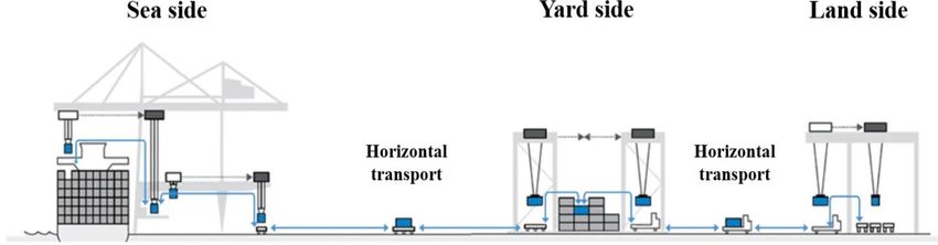
1. Introduction
As defined in the project description of InterGreen-Nodes, Deliverable D.T3.1.3 includes a market
analysis on the expectation of ports towards green fuel vehicles. Based on this first analysis,
concepts for alternative fuel vehicles (rail and road) use in terminal shunting services and
operations are being derived. The deliverable focusses on battery electric vehicle and hydrogen
fuel cell vehicles, as these drivetrain types promise very high potentials for CO2 savings, while at
the same time are the most challenging, as performance data needs to be translated into technical
requirements, for which only little experience exists.
Based on models, partly developed by the research group transport logistics of the Technical
University Wildau (PP1), the technical requirements were calculated, using the requirements
formulated by the ports. The calculations included the energy requirements, dimensions of energy
sources, and performance definition for the drivetrains (based on the operational programme).

2. Introduction to terminal operations
As the interface between the individual modes of transport, intermodal terminals are considered
to be the heart of CT. The respective freight is handled in terminals of ports and freight villages.
If a terminal is connected to three modes of transport, it is defined as trimodal terminal (p. 3).
Likewise, a node of two modes is referred as bimodal. Three types of services are offered in
terminals: handling, storage and additional services.
A typical example of additional services is the repair of lifting equipment or containers. Some
intermodal transhipment centres also offer so-called trucking as a service, where the terminal
operator transports the loading unit of customers over the main and final leg with its own
trucks. The specific scope of services of each transhipment node is dependent on many factors
such available space as well as transport connections or customer needs. The general
operation areas of a trimodal terminal as well as the flow of transports can be seen in Figure
1.
It is based on a container transport, which takes place within road, rail, inland waterway and
maritime traffic networks. In container terminals, there are three main areas, which are sea
side, yard side and land side. The respective areas are linked by horizontal transports. For
each sector, various operations are executed. Additionally, many processes in the terminal
are supported by technical equipment.
There are also other types of terminals, which are named according to the goods that are
handled. Examples are roll-on/roll-off or bulk cargo terminals. They deviate in certain aspects
from container transport, such as transhipment technique and handling equipment.
Nevertheless the basic structure is identical, which is why they will not be examined in detail
in the further course.

 Page 3
Figure 1: Container terminal system (own figure)

Sea Side
When arriving at the port, cargo vessels wait to moor at the quay. This platform represents the
interface between terminal and ship. Alongside the quay, several berths can be found, to which
the vessels are assigned. The ships are then moored. Next, the loading and unloading operations
by quay cranes begin. The containers that are loaded on vessels are called export containers. They
were previously delivered to the terminal from consignors. Import containers are unloaded from
the vessels and need to be delivered to their respective recipients. After unloading, the containers
are transferred from the quay to the yard side. They are moved by horizontal transport equipment
such as reach stackers and terminal tractors. Depending on the layout of the terminal, the loading
units can also be transhipped directly onto external trucks or trains from the quayside cranes.

Yard Side
As the centre area of a terminal, the yard side interacts with seaside and landside operations. A
yard typically accounts for up to 70 % of the total terminal area. It represents an intermediate
storage facility, in which containers remain from a couple of hours up to several weeks. Due to
the fact, that storage space is limited, multiple containers are stacked by container handlers.
The yard side enables a temporal decoupling of the transport links. For instance, export containers
can be delivered before the arrival of the dedicated vessel and import containers can be picked
up for further transport when the delivering boat already left the terminal. Some terminals also
operate a depot of empty containers, which are stored at assigned areas. They are also stacked
temporarily until they are used again. It is not always possible to reload containers for onward
transport immediately after unloading. Sometimes transporting an empty container to its new
loading location costs more than the container itself is worth, which is why they are only sent on
in bundles.

 Page 4
Land Side
The land side is the interface to the land transport modes. External trucks have to pass gate
houses, where containers and transport documents are checked. The layout of the landside area
is determined by the connected transport modes. If the operations of external trucks are
predominant, this functional area can also be integrated in the yard area. The trucks are then
loaded at assigned spaces at the end or in the middle of the stacking yard. In order to serve trains,
railway tracks lead into the terminal. Containers are brought by horizontal transport equipment,
such as terminal tractors, to cranes ,which take over the vertical handling. For this purpose,
mobile reach stackers are also used. Unloading and loading takes place outside the stacking area
in order to avoid crossing of rail tracks by yard vehicles. In this way, the safety of the terminal is
increased among others. In addition to loading tracks, terminals also have side-tracks, which
enable shunting operations of wagons. A diesel locomotive is usually used for this purpose. In some
cases road-rail vehicles are deployed for shunting operations as well. As the name suggests, this
is a dual mode vehicle, that can travel on both rail tracks and road.
Other layouts include sites which are located in or near the terminal premises. They include offices
for staff, that is responsible for administrative activities. Furthermore, the terminal operator
provides office accommodation for other entities such as customs, security or mooring companies.
Moreover, maintenance workshops for repairing terminal equipment could be found in terminals
as well.

 Page 5
3. Zero-emission vehicles
3.1. Definition
The drive concepts investigated will be narrowed down and consequently only so-called zero-
emission vehicles will be considered. These are defined as vehicles that do not emit any pollutants
during operation and standstill.
The term is based on an environmental legislation passed by the California Air Resources
Board, which has boosted the development of environmentally friendly vehicles since the
1990s. There are various drive concepts, but only two configurations can be assigned to the
zero-emission class, as these do not emit harmful tailpipe emissions.
Firstly, there are battery-powered vehicles. Secondly, there are FCEV that only emit water vapor,
which is not a pollutant. Alternative concepts, that use natural gas or synthetic fuels, can also
lead to a significant reduction of emitted air pollutants. However, since they do not completely
fulfil the zero-emission condition, they are not considered further. Last but not least, it should be
mentioned, that battery-powered as well as hydrogen-powered vehicles are not free of pollutant
emissions when considering the complete life cycle. For example, emissions along the production
process for the energy sources have to be taken into account

3.2. Battery electric vehicles (BEV)
The development of battery-powered automobiles has a long history. The technology is even older
than the invention of petrol-powered vehicles with internal combustion engines (ICEV). The first
battery-powered vehicle was built in 1834, more than 50 years before the introduction of the
ICEV.
However, further development of electrically powered vehicles was dampened by the fact that
they could not compete economically with gasoline and diesel technology. As a result, electric
vehicles largely disappeared from the market until the 1930s, and their further development was
not encouraged until the oil crisis in the 1970s. Before the turn of the millennium, this was
reinforced by an increased demand for greater environmental protection. Over the years, the
technology and its technical components have been further optimized in terms of efficiency.
BEV are characterized by a simple system structure. The energy required for driving is stored in a
battery that supplies an electric motor and all auxiliary units such as air conditioning or heating.
The battery’s electric energy is provided by electrochemical processes and converted into a
rotational movement by the electric motor. With the help of a differential, the torque is
transmitted to the wheels, as in conventional vehicles. Battery-powered drive systems do not
always consist of one central motor, but can also be equipped with several individual wheel
motors. In addition, electric motors can also be used as generators to feed the vehicle's kinetic
energy back into the battery during braking. To ensure proper driving operation, the capacity of
the battery must be sufficient for all driving situations as well as allowing an appropriate range.
The range is dependent on a lot of factors such as “driving condition and style, vehicle
configurations, road conditions, climate, battery type and age”.
 Page 6
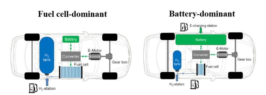
There are several types of batteries that differ in terms of their technical and economical
properties. Lithium-ion (Li-ion) batteries have proven to be suitable energy storage systems. At
present time, they are “the leading type of batteries found in electric vehicles due to their high
energy density, high efficiencies, and lightweight”. Accordingly, an energy density of roughly 200
Wh/kg is achievable, which means that a Li-ion battery with a capacity of 100 kWh weighs at least
500 kg, for instance.

3.3. Fuel cell electric vehicles (FCEV)
Similar to battery drive train concept, the fuel cell is not a new invention. The functional principle
of this technology was discovered as early as 1838, after the chemist Christian Friedrich Schönbein
recognized, that electrical energy is released when water and oxygen react. In the following year,
the physicist Sir William Robert Grove was able to develop the first fuel cell based on this principle
(ibid.). Nevertheless, a rapid development was prevented due to the complicated operation at
that time. That is why the fuel cell technology could not prevail against the mechanically driven
dynamo machine developed at the same time.
Fuel cells were only used for special applications in the further course, as for example in aviation.
Nevertheless, the technology of the fuel cell gained more and more importance in the last years
in the context of efficient and emission-free transport systems. This is due to enormous
development progress in recent years, in which the performance was significantly increased as
well as manufacturing costs reduced. Increasing market launches of several hydrogen-powered
products prove this as well. The mode of operation of the fuel cell can be understood as a reversed
electrolysis. In electrolysis, water is split into hydrogen and oxygen using electrical energy. In a
fuel cell, this reaction is reversed and electrical energy is released. Thus, in contrast to the
battery, the fuel cell is not an energy storage device, but can be seen as an energy converter. As
it generates electric current and no torque, an electric motor is needed for propulsion. The motor
is supplied with electric current via power electronics, which then drives the vehicle via a gearbox.
In addition to the fuel cell itself, a pressure tank for storing the fuel is required to generate
energy. Moreover, a traction battery is installed, with which excess electrical energy as well as
converted braking energy can be stored. Apart from that, the battery is also responsible for power
bridging or short-term coverage of peak load requirements from the electric motor. FCEV are also
referred to as serial hybrids with two energy storage devices (H2 tank and battery) on the one
hand, and two energy converters (fuel cell and electric motor) on the other hand. The powertrain
design is usually classified into the dominant fuel cell drive and the range extender drive according
to the main provision of the drive energy. Figure 2 shows the different configurations.

 Page 7
Figure 2:FCEV configurations (own figure)

In the dominant fuel cell system, the driving power requirement is met with the fuel cell, and the
battery is used exclusively for the recuperation of braking energy during deceleration and power
assistance during acceleration. The fuel cell is therefore very powerful, the battery is usually of
high power density and low capacity, and the hydrogen tank is designed as a high-pressure tank,
containing several kg of H2 to achieve high ranges. Energy is only supplied by refueling with
hydrogen. In the case of the range extender drive, the driving power requirement is covered by
the battery, while the fuel cell is used to charge the battery while driving, thus extending the
vehicle's range. Range extender vehicles usually have a battery with lower power density and high
capacity, a fuel cell with low power and a small-volume hydrogen pressure tank. In the case of
range extender drives, the larger battery permits a plug-in vehicle design. This means, that in
addition to hydrogen refueling, the vehicle's energy is supplied by charging the battery via the
power grid. Mixed forms of the two variants are possible. These are also referred to as the "mid-
size fuel cell" concept. There is a large number of different fuel cell types. Stan gives an overview
of variants realized so far with their respective characteristics and areas of application.
Accordingly, proton exchange membrane fuel cells (PEMF) are particularly suitable for vehicles
due to their very high power density at operating temperatures of 20 to 120 °C. Furthermore, the
fact that it has a flexible operating behavior and the possibility of using oxygen from an air flow
also speaks in favor of its use. Rechberger also mentions a fast and cold start capability as well as
high efficiency, which is why this fuel cell type is preferred in the automotive industry.

3.4. Comparative analysis between BEV and FCEV
Both drive concepts have individual advantages and disadvantages. In the following, the two
concepts will be compared with each other based on selected criteria. In addition to technical
issues, infrastructural aspects are also considered. With regard to the efficiency of both drive
concepts, battery-powered vehicles have an edge over FCEV (FVEE, 2014, p. 111). Due to the
simple system design, an efficiency of up to 80 % can be achieved. With fuel cell technology,
efficiencies of 40 to 50 % are possible. Nevertheless, these values are higher than those of the
conventional combustion engine, which only achieves an efficiency of 25 %. There are also
considerable differences in terms of energy densities. Due to the fact, that the energy density for
batteries is lower than for hydrogen, battery-powered vehicles are heavier. Eberle et al. illustrate
this in an example showing the relationship between diesel, hydrogen and battery power (2010,
 Page 8
p. 230). For a vehicle with a range of 500 km, a diesel tank system of 43 kg weight and 46 l volume
would be required. On hydrogen basis the specifications of the tank system would increase to 125
kg and 260 l. Battery systems are the worst performers: for a range of 500 km, an energy storage
system with 830 kg and 670 l would be required. Additionally, Thomas states, that the vehicle
mass grows more than linearly if it should achieve a greater range (2010, p. 305). This is because
not only more batteries must be added for each additional km, but also the motor or braking
system must be reinforced as a consequence of increased vehicle weight. In contrast, FCEVs can
achieve longer ranges without greatly increasing vehicle mass. For FCEVs, the range increases with
the size of the fuel tank, making them comparable to conventional vehicles in this respect (Belmer
et al., 2019, p. 24). Consequently, hydrogen-powered vehicles offer range advantages over BEVs.
This also relates to the ability to carry payloads, which is a critical variable for transportation
logistics. When designing a BEV, there is often a tradeoff in terms of range as well as achievable
payload. To overcome potential operational limitations of BEVs, Teoh et al. summarize several
strategies (2018, p. 2). One possibility is to reduce the scope of services. This could be realized
by decreasing the number of served customers as well as the size of the served area. Another
possible strategy describes the modification of transport operations by optimizing routes and
schedules or increasing the fleet size. Furthermore, the use of opportunity charging is mentioned
as another measure.
Another benefit of fuel cell technology over BEV is the lower influence of environmental conditions
on the operating behavior (Belmer et al., 2019, p. 26). Accordingly, an additional energy
consumption of about 10 % can be expected in winter operation compared to average operation.
In comparison, batteries are more sensitive to extreme weather conditions. This manifests in a
loss of usable capacity and accelerated aging behavior. Charging the battery is another limitation,
as the charging time is comparatively high. This may result in limited flexibility during operation.
FCEV, on the other hand, have a rapid refueling time. Refueling behavior is similar to that of
conventionally powered vehicles (ibid., p. 20). As with gasoline or diesel systems, the refueling
process is accomplished through dispensing devices. The aspect of the refueling time and the
associated idle time is especially important for economic enterprises, which have only a small
time window within their activity patterns. In terms of infrastructural aspects, the use of BEV is
in great advantage (Michalk, 2018, p.7). For example, electricity is already produced on a very
large scale, so no additional facilities are needed. Additionally, distribution networks already exist
in form of electric grids. As a consequence, no further delivery or storage infrastructure is needed.
Moreover, area consumption of charging stations is another perk as they are comparably small.
For hydrogen storage and distribution specifically assigned spaces are necessary for safety reasons.
Additionally, the refueling infrastructure and its related costs for hydrogen-powered vehicles are
a prevailing barrier to widespread viability (Moultak et al., 2017, p. 30). Table 1 summarizes the
results of the analysis.

 Page 9
Parameter BEV FCEV

 Efficiency ++ +

 Range - +

 Refueling/Recharging - +

 Infrastructure + -

In summary, no concept is optimal for all applications. The set of decision parameters requires a
very detailed examination of the vehicle requirements. Depending on the prioritization of the
characteristics for the corresponding application profile, the drive concept must be selected. BEV
are particularly suitable for lighter vehicles with low ranges. FCEV, on the other hand, are the
better alternative for larger and heavier vehicles.

 Page 10
4. Preliminary work done in the Interreg BSR project
Scandria2Act
The objective of the project Scandria2Act from 2016 to 2019 was the promotion of multimodal as
well as sustainable transport actions in the Scandinavian-Adriatic corridor. One aspect was the
deployment of green fuels, on which Michalk put the most relevant details in a report. Accordingly,
electromobility is particularly “well suited in order to install green solutions in city logistics”
(Michalk, 2018, p. 6).
Furthermore, the report contains a step-by-step instruction on how to purchase battery electric
vehicles for logistics applications.
The first step is to define the objective to derive success indicators. This includes for instance the
definition of the reasons for introducing an electric vehicle. After that, one can estimate the
necessary range and annual mileage of the vehicle. It is important to have a clear idea of the tour,
on which the electric vehicle will operate. For that, it is helpful to analyze vehicle logbooks to
derive potential tours with mileages that could be covered by electric vehicles. In the third step
the gross weight of the vehicle as well as the necessary payload needs to be specified. For
example, the gross weight of the current vehicle(s) to be replaced can be taken as a starting point
which will be applied to the electric vehicle. Another approach is to define the required payload
and then search for vehicles that have this capacity and find the corresponding gross weight. In
step four the necessary battery capacity based on defined range and gross weight criteria is
estimated. The following formula is used for the estimation.

 Energy demand / Battery capacity [kWh] =
 (max. Range [km] · 0.3413 + Vehicle gross mass [t] · 1.3579 + 28.57) · 1.2

The formula was used through a regression analysis with n=10. As you can see in the formula, a 20
% safety-addition on capacity is included and covers conventional auxiliary users such as heating
and air conditioning. The fifth step focuses on the estimation of costs. Regarding the purchasing
price the following formula is given for a rough calculation, which was also developed through a
regression analysis with n=10.

 Purchasing price [€] =
 Vehicle gross mass [t] · 2810 + Battery capacity [kWh] · 920 + 2262

Maintenance costs are estimated to be around 60 to 80 % of the cost of equivalent diesel vehicles.
However, it should be noted that this is only a rough estimate, as no comprehensive long-term
data is available. For energy costs, consumption can be estimated using the formula below.

 Consumption (kWh/km) = Battery capacity [kWh] / max. Range [km]

 Page 11
Again, this is only „very rough estimate and it will vary greatly with load, but also with weather
and road conditions“(p.23). Once the consumption is calculated, it can be multiplied with the
current price per kWh to obtain the consumption costs. In step six the savings of CO2 emissions
are calculated. For that, the current emissions have to be estimated by determining the average
fuel consumption per km of the vehicles that will be replaced. After that one can multiply it with
the mileage. This result will then again be multiplied with factor 3.16 for a diesel or 2.88 for a
gasoline engine. For the planned electric vehicles the CO2 emission factor per kWh can be obtained
from the energy supplier. Multiplying this value with the total consumption, will give the CO2
emissions for the vehicle, which can be compared with the previously used vehicle. Again, Michalk
states, that it is only a very rough estimate, which could be refined with in-depth analysis of
utilization- and tour profiles (ibid.).
Step seven includes the selection of the vehicle on the market that matches the requirements and
contacting the vendor. In the report, there is a vehicle catalogue, which lists several options of
battery electric vehicles (ibid., p.26ff.). A market research will have to be conducted in case there
is no suitable alternative available. In the eighth step, one can clarify open questions with regards
to the charging infrastructure as well as maintenance, which are of economic importance. Michalk
lists several questions (p.23f.) One possible question is to ask about the necessity of own charging
stations or the feasibility to use public stations. Regarding maintenance, one possible question
would be if the vendor offers a battery exchange after a certain mileage. The last step covers the
selection of a funding program. For that, the report also provides a catalogue of several programs
in the Baltic Sea region to facilitate the search (ibid., p. 29f.). In fact, subsidies are still needed
to penetrate the logistics market as high purchasing costs are a major challenge.

 Page 12
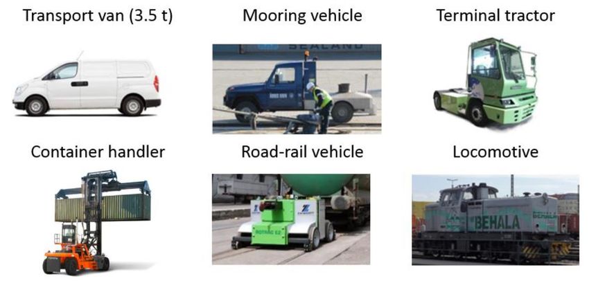
5. Market study
5.1. Method
As the present study is mainly a retrieval of technical requirements, the means of a written survey
was chosen. This appeared to be the most sensible method. For example, the form of expert
interviews was considered unsuitable, since interviewees should be given the necessary time to
coordinate the answers internally in their departments. A previous questionnaire was also used as
a guide, which had already been prepared by the research group before this thesis was carried
out. It contains initial questions to specify vehicles that could use a green drive technology. The
questionnaire has already been sent to and answered by a participating terminal operator in a first
preliminary study (see Attachment A). In the course of this, four different vehicle platforms were
identified and specified: a transport van in the 3.5 t class, a terminal tractor, a locomotive and a
road-rail vehicle. These platforms were considered in the following investigations. For the
technical implementation of the present empirical study, an Excel template was created. For each
vehicle platform there are 10 questions for specification. The majority of these are open
questions. For individual parameters, there were suggested answers based on drop-down lists to
increase the quality of the answers. The four vehicle platforms identified in the preliminary study
were integrated into the survey. In addition, the mooring vehicle was added as another platform,
as it was identified by the project manager as a possible vehicle. In the questionnaire, the terminal
operators were asked to specify the five vehicle platforms in terms of their requirements. In
addition, they were given the opportunity to add and characterize other relevant vehicles. With
regards to the structure of the questionnaire, the exact application purpose was to be described
in detail firstly. The respondents were then asked about the desired maximum range for a duty
cycle and were also requested to estimate the maximum acceptable idle time for recharging or
refueling the vehicle. Other parameters were the maximum permissible gross weight and the
desired payload or alternatively towing capacity. The questionnaire also covered relevant auxiliary
units for the respective vehicles. Further questions related to the number of needed vehicles as
well as the models currently used for this purpose. In addition to technical aspects, terminal
operators also had to estimate the maximum acceptable purchase price for these vehicles. Finally,
the respondents had the opportunity to make further comments, which had not yet been covered
by the previous questions. The questionnaire was developed in close collaboration with the
research group. While the survey was not intended to provide in-depth information for a complete
technical design of the vehicles, it is an initial retrieval of basic requirements. This ensures, that
the requirements can be easily determined and that the asked terminal operators involved are not
overburdened. These user requirements can then be forwarded to manufacturers of special
vehicles to drive demonstrator development. The questionnaire was sent to the stakeholders in
October 2020 by the project manager of the InterGreen-Nodes project with a request for
processing. Including the preliminary study, the user requirements of five project partners were
recorded by the end of the year, which are described in the further course.

 Page 13
5.2. Participants
Berlin
One of the players involved is the company BEHALA, which is located in the region of Berlin. With
about 120 employees, the company operates one of the largest inland ports in Germany in Berlin
(BEHALA, n.d.). A handling and transport volume of about 4 million t is achieved per year. The
scope of services include the handling of bulk, general and heavy lift cargo. Moreover, its
operations comprise the handling of containers. BEHALA operates its own trains as a rail transport
and infrastructure company, with which freight trains can be picked up in Berlin and brought
directly to the ports, where the goods are then loaded onto a ship. The company is considered as
a development driver of logistically sustainable solutions. In this respect, InterGreen-Nodes is not
the first project, in which BEHALA has been actively involved. For many years, "BEHALA has been
committed to electric mobility for freight transport, and very successfully deploys a 100 % electric-
powered tractor-trailer unit, small vans, cars and railway shunting equipment" (VML-BB, n.d.).

Rostock
With a total area of 750 ha, the Port of Rostock is the largest German port in the Baltic Sea region.
It is the fourth largest seaport in Germany after Hamburg, Bremerhaven and Wilhelmshaven
(Rostock Port, 2020a, p. 18). In 2019, approximately 25 million t were handled in total. The
number of direct and indirect employees of the Rostock port industry is about 16,000 (Rostock
Port, 2020b, p. 2). Rostock Port GmbH is responsible for the management, development and
maintenance of the respective infrastructure. With its seven different terminals, the seaport has
a wide range of services. Upstream of the port is a marshalling yard with about 180 km of track.
In addition, there are 54 km of tracks on the port site that enable a direct transshipment without
additional storage time of the goods (ibid.).

Koper
The port of Koper is located in the northern part of the Adriatic Sea. It is the only Slovenian
multipurpose port. Luka Koper Group, which was founded in 1957, has about 1,600 employees and
operates 12 specialized terminals and its port activities are related to cargo and passenger
transport (Richter, 2019, p. 2). The core business of the port comprises the transshipment and
warehousing of a variety of goods. The port area consists of 280 ha of land. Additionally, there
are 35 km of railway tracks within the port area. In 2018 the total throughput amounted to
approximately 23 million t (ibid.). As the largest container terminal in the Adriatic as well as third
largest car terminal in the Mediterranean region, the port has a significant effect on the national
economy (Slobko Jerman, 2016, p. 2)

Bologna
The Interporto Bologna is a freight village and located in the Emilia-Romagna region, which is one
of the most heavily industrialized areas in Italy (Haug, 2019). It covers a total area of 410 ha and

 Page 14
features a railway system, that is larger than 65 ha (Interporto Bologna, 2019, p. 2). The logistics
hub includes three bimodal terminals. At the freight village, roughly 120 transport and logistics
companies are located, which employ more than 4,000 people in total. In 2018, Interporto Bologna
handled 1.2 million t of rail freight goods as well as around 12.7 million t of trucked goods (Haug,
2019).

Budapest
The last project partner is the Freeport Budapest. It is a logistics center with an area of 153 ha,
in which warehousing, railway and shipping services are offered (BSZL, 2019, p. 3). The freight
village operates the only trimodal container terminal in Hungary (ibid., p. 6). In terms of railway
operations, Freeport Budapest has a track network with a length of about 16 km. In 2016, almost
one million t goods were transshipped in total (Jovanovic, 2017, p. 81).

5.3. User requirements for selected vehicle platforms
In the further course of this study, six vehicle platforms named and specified by the interviewed
terminal operators are examined in more detail. These include road vehicles such as a transporter
with a maximum total weight of 3.5 t, a mooring vehicle, a terminal tractor and a container
handler as well as rail-bound vehicle platforms like a road-rail vehicle and a locomotive. Other
vehicles were also named in the survey, but these will not be considered further due to various
reasons. For instance, a boat was specified, which is not in the scope of the work package as it
only considers road and rail vehicles. The identified vehicles along with their required
specifications can be viewed in Attachment A and B.

 Page 15
Transport van (3.5 t)
For the majority of the interviewed terminal operators, the van would be used for transport of
maintenance equipment and supervisory tasks. Additionally, the freight village Bologna mentions
the usage for last mile express delivery outside the port area. Depending on the specific
application, maximum distances between two charging cycles range from 200 to 1,000 km.
Regarding the desired payload, the ports specify a range from 1 to 2 t. Typical auxiliary units like
heating, air conditioning and radio were considered desirable. The port of Berlin also mentioned
the possibility to charge an external battery, which can be charged by the van. Since there is not
any further quantitative data, this point was not considered in the ongoing technical dimensioning.
Most of the respondents indicated a duration of at least eight hours for the longest acceptable
idle time between two duty cycles. Only the port of Rostock specified a maximum duration of two
hours for reloading or refueling. With regard to the maximum purchase price, the two ports
Bologna and Koper stated a limit of 50,000 €. For other ports, a zero-emission transporter with a
total weight of 3.5 t should cost a maximum of 20 to 50 % more than a conventional fuel driven
vehicle. Regarding the currently used vehicles, the port operator Rostock uses the vehicle models
Vito and Sprinter from the manufacturer Mercedes-Benz for the purpose of equipment transport.
In Budapest Dacia Duster and KIA K2500 are used for maintenance and supervisory tasks. The most
important parameters can be found in Table 2. In addition, the original answers of the
questionnaire can be viewed again in Attachment A and B.

 Parameter Berlin Rostock Bologna Koper Budapest

 Last mile Internal Maintenance
 Craftsman Equipment
 Purpose express logistic & &
 transport transport
 delivery maintenance surveillance

 Max. Range
 250 200 600 500-1,000 200
 [km]

 Max. Payload [t] 1,5 2 1,5 2 1

 Gross weight [t] 3,5 3,5 3,5 3,5 3,5

 Max. Idle time
 n.a. 2 8 >8 8
 [h]

 120 % of a 150 % of a
 Max. price [€] n.a. 50,000 50,000
 diesel van diesel van

 Currently used MB Vito & Citroen, Dacia Duster
 n.a. n.a.
 vehicle Sprinter Ford, a.o. & Kia K2500

 Page 16
Mooring vehicle
The two ports of Rostock and Koper can imagine using mooring vehicles with green propulsion
systems. This vehicle type is used to fix vessels at the pier. The interviewee of the German port
states a required maximum range of 200 km per duty cycle. According to the Slovenian project
participant, the car needs to reach 500 km for its mooring operations. With regards to the towing
capacity the vehicle would have to tow a mass of two t. When considering relevant auxiliary units
in addition to heating and air condition systems, the Slovenian port indicated, that there must be
enough battery power to operate a spill winch used for mooring. Furthermore, the terminal
operator in Rostock states two hours as longest acceptable time frame for recharging or refueling.
For the operations in Koper it would be sufficient to keep the idle time of this vehicle type at
more than eight hours. Regarding the purchase price, the expectations are the same as for the
transport van with a gross weight of 3.5 t: Rostock would accept a 20 % higher price compared to
a conventionally powered vehicle and Koper fixes a maximum value of 50,000 €. The number of
vehicles required per port is in the single digits area. The German port uses one mooring vehicle
and the Slovenian five. The currently used models are the Unimog from Mercedes-Benz and the
Hilux from Toyota. These versions will be discussed in more detail on the following pages. The
answers of both ports are summarized in the following Table:

 Parameter Rostock Koper

 Support port crew to
 Purpose Mooring operations
 moor vessels

 Max. Range [km] 200 500

 Max. payload [t] n.a. 2

 Gross weight [t] n.a. n.a.

 Max. Idle time [h] 2 >8

 Max. Price [€] 120 % of a diesel model 50,000

 Currently used vehicle MB Unimog Toyota Hilux

 Page 17
Terminal tractor
The terminal tractor was specified by Berlin, Bologna, Koper and Budapest. According to the Italian
freight village, this vehicle platform will be used for shunting operations with semitrailers between
warehouses or parking areas. Most of them are used in container terminals, but they are also
integrated in the transport operations of timber and general cargo terminals. The port of Berlin
also considers the use of yard tractors on public roads outside the port area. Depending on the
intended application, the transshipment centers have specified desired maximum ranges from 40
to 400 km. In terms of the required payload, the terminal tractors should be able to carry at least
20 t. Furthermore, the freight village Bologna requests, that the vehicle needs to be capable to
move at least one complete semi-trailer with an average weight of 35 t. With 60 t, Koper indicates
the heaviest payload to be carried within the port. Regarding the gross weight of the tractor
without trailer, the Hungarian project participant states it as about 10 t. The idle time for this
vehicle type ranges from four to more than eight hours in order to refuel or recharge. Conventional
vehicle models that are used by the participating ports are produced by the manufacturers such
as TICO, Kalmar, Terberg and Mafi. In case these vehicles should be replaced by zero-emission
yard tractors, the maximum purchasing costs are 100,000 € (Bologna) and 200,000 € (Koper). The
port of Budapest stated, that a new electric terminal tractor costs around 250,000 € net, which
would be too expensive. In general, it sees no need for replacing its current diesel tractors since
accordingly they are still in perfect condition after 15 years of operation. In the following table
you can find the answers from the project partners.

 Parameter Berlin Bologna Koper Budapest

 Shunting of
 Container Shunting in
 semi trailers Shunting
 transport container,
 between inside
 Purpose within port timber &
 warehouses or container
 and on public general cargo
 in parking terminal
 roads terminal
 areas

 40 (if only
 Max. Range
 inside port) / 400 400 100
 [km]
 60

 Max. Payload [t] 40-44 35 60 25

 Gross weight [t] n.a. n.a. n.a. 10 t

 Max. Idle time [h] n.a. 4 >8 8

 Max. Price [€] n.a. 100,000 200,000
Container handler
The container handler was specified by Budapest (see Table 5). The task of this vehicle platform
is to maneuver and stack containers. In order to be able to replace the currently operating diesel
models of this vehicle type, Budapest specifies a maximum range of 100 km between charges. Two
different variants of the container handlers are required, varying in terms of their transported
payload. Firstly, a capacity of 11 t is required to ensure the transport of empty containers.
Secondly, the port would need a heavier version with a lifting capacity of 45 t. With regard to the
maximum gross weight, a value of 70 t was estimated, which will be validated in the market
analysis part. Empirical study 33

Budapest states, that it is still acceptable to have an idle time of eight hours for this type of
vehicle. Regarding the auxiliary units, apart from heating and air condition systems, no other units
were specified by the port and it did not defined a maximum purchase price. Currently, 10 cargo
handlers are in operation in Budapest: six with a capacity of 45 t and four with a capacity of 11 t.
Both versions are from the special vehicle manufacturer named Kalmar.

 Parameter Budapest

 Purpose Handling of (empty) containers

 Max. Range [km] 100

 11 (empty containers) &
 Max. payload [t]
 45 (loaded containers)

 Gross weight [t] 70

 Max. Idle time [h] 8

 Max. Price [€] n.a.

 Currently used vehicle Kalmar 11 t & Kalmar 45 t

 Page 19
Locomotive
The locomotive was specified by four ports. It is used for shunting and line operations of trains
and wagons. For these purposes, it can either be used inside or outside the port. According to the
requirements of the Berlin port operator, the locomotive must be able to run 100 km with full
load without any interruptions. The other ports did not specify a distance, but did so for operating
hours. Here the running times between two charges differ. While Budapest indicates a running
time of 10 hours per day, it is 70 h for the Italian transshipment point from Bologna. The longest
desired running time is 500 operating hours for Koper, which seems to be a typo. According to
three of the ports, the locomotive must be able to pull a load of at least 2,000 t. Berlin additionally
states, that a propulsion power of 1,700 kW is required for this. Budapest demands an even higher
towing capacity. The gross weight of the locomotive is estimated at around 60 to 80 t in order to
pull the respective masses. Additionally, the longest acceptable idle time is at most eight hours
for two ports and only Koper permits a longer idle period. The involved interviewees also stated,
that they needed two to three locomotives for their purposes. With regard to the purchase price,
two ports indicated a maximum permissible limit of 1.7 million and 2.2 million € each. Currently,
mainly models from the rail vehicle manufacturers CZ Loko and Vossloh are used. The table
summarizes the most relevant parameters.

 Parameter Berlin Bologna Koper Budapest

 Deliver/Dispatch
 Shunting/ Line Train and wagon Shunting
 Purpose train sets inside
 Locomotive shunting operations
 whole port

 70 working 500 working 10 working
 Max. Range [km] 100
 hours hours hours / day

 Max. towing capacity
 2,000 >2,000 2,000 >2,000
 [t]

 Gross weight [t] n.a. n.a. 64-84 72

 Max. Idle time [h] n.a. 8 >8 8

 Max. Price [€] n.a. 1.7 million 2.2 million n.a.

 CZ Loko, MÁV Class M44
 Currently used vehicle n.a. CZ Loko
 Vossloh & 74 SK

 Page 20
Road-rail vehicle
The project partners Berlin, Bologna and Koper see the potential for using green road-rail vehicles.
According to them, this vehicle platform is used for light shunting operations of trains and wagons.
In the context of short movements, only short ranges are achieved during a duty cycle. Berlin
estimates these at 10 km for example. Bologna specifies a working duration of 50 hours. The road-
rail vehicle must be designed in such a way, that a mass of about 1,000 to 1,500 t can be towed.
Koper is the only respondent to state, that the gross vehicle weight must be in the range of 25 to
35 t to be capable of towing these volumes.
With regard to the idle time, respondents agree, that a maximum of eight hours would be
acceptable. In contrast, there are high deviations in the required purchase price. Bologna
considers the road-rail vehicle as too expensive with a price above 120,000 €, while Koper has a
tolerance limit of 650,000 €. Moreover, the required number of this vehicle type ranges from one
to seven according to the interviewees. Currently used models are for instance the converted
Unimog from Mercedes-Benz as well as different versions of Zwiehoff and Zephir.

 Parameter Berlin Bologna Koper

 Train and wagon Movement of train
 Purpose Light shunting
 shunting sets in terminals

 Only short
 Max. Range [km] 10 50 working hours
 movements

 Max. Towing
 1,000 1,500 1,000
 capacity [t]

 Gross weight [t] n.a. n.a. 25t-35t

 Max. Idle time [h] n.a. 8 >8

 Max. Price [€] n.a. 120,000 650,000

 Currently used MB Unimog,
 n.a. Zwiehoff, Zephir
 vehicle Zephir

 Page 21
6. Implications from the empirical study
6.1. Derivation of technical properties
In order to estimate the energy demand for the individual vehicle platforms, the formula
developed for the Scandria2Act project was used. However, during the project, it became clear,
that the formula was subject to some restrictions. For example, the energy demand could only be
determined for light road vehicles. As a result of this, the formula was only used for the transport
van, the mooring vehicle and the terminal tractor. For the other vehicles, an alternative
methodology was worked out case by case, which will be described in more detail in the respective
subsections. Two additional parameters were derived from the estimated energy demand. The
first is the battery weight. This parameter can be determined by dividing the battery capacity by
the specific energy density. In this thesis, an energy density of 200 Wh/kg will be used for the
calculations, as it is the upper limit for Li-ion batteries, which are most commonly used in BEV.
The second parameter is the charging capacity. It describes the infrastructural requirements to
enable battery recharging within a certain period of time. Its calculation is based on the maximum
acceptable charging time specified by the surveyed project partners. The charging capacity can
be roughly estimated by dividing the battery capacity by the charging time. In addition, a 15-
minute safety buffer was added to the times from the survey.

Transport van (3.5 t)
For the transport van with a total weight of 3.5 t, the desired distance of 200 km results in a
battery capacity of 122 kWh. With an additional 50 km, the battery capacity increases by a further
20 kWh to 142 kWh. With a range increase from 200 to 500 km, the required energy doubles to
245 kWh. For the 600 km range indicated by the port of Bologna, the battery capacity would be
286 kWh. For a distance of 1,000 km in combination with a gross vehicle mass of 3.5 t, 450 kWh
would be needed according to the formula.
With regard to compliance with the charging times, the following conclusions can be drawn. The
maximum charging capacity is 70 kW as required by the port of Rostock, which defined two hours
as acceptable charging time for 122 kWh. In the case of Budapest, where even eight hours would
be feasible for charging the same battery capacity, a charging capacity of 16 kW would be
sufficient. In the case of Koper, the 450 kWh battery requires a charging capacity of at least 58
kW to fulfil the time requirement of eight hours. Thus, for each case, the vehicles be charged with
already developed charging stations. Regarding the payload for conventionally powered vehicles,
it can generally be said, that it is limited to about 1.5 t for versions with a total weight of 3.5 t.
For instance, the payload of the diesel-powered version of the Mercedes-Benz Sprinter vehicle
used by the port of Rostock is about 1.5 t. For the other mentioned vehicle models like Mercedes-
Benz Vito and KIA K2500, the transport weight is limited to one t. Some ports specified a desired
payload of two t for the green propulsion solution, which is not feasible for this vehicle platform.
When considering the battery weight, it becomes clear, that for most of the applications the range
and payload requirements are not feasible. For Budapest with 600 km range, the batteries would
weigh about 1.4 t. For 450 kWh, even more than 2.2 t would be needed, making a battery/gross

 Page 22
weight ratio of 64 %. It should be emphasized once again, that the energy density of 200 Wh/kg is
roughly the upper limit of Li-ion batteries. Using a more conservative energy density would
increase the mass of the battery and consequently reduce the payload.

Mooring vehicle
Mooring vehicles are modified flatbed trucks. At first, the weight class for this application is
determined. According to the survey, the vehicle models used are the Hilux from Toyota and the
Unimog from Mercedes-Benz. The Hilux has a maximum gross weight of approximately 3.2 t
(Toyota, 2018, p.10). It is also assumed, that a maximum gross weight of 3.5 t is sufficient for the
Unimog in this application. Therefore, the previously estimated energy demands for the transport
van can be transferred to the mooring vehicle. The required ranges are 200 and 500 km. At 200
km the demand is 122 kWh and at 500 km it is 245 kWh. The main task of this vehicle platform is
to transport the mooring personal to the vessels as well as to haul in ship's lines with an electric
winch machine. In comparison to the transporter, it is therefore considered likely, that the
payload requirements are lower and there is accordingly more space for a larger battery. In
addition to the consideration of the horizontal movement, the energy required for the electric
winch machine must also be taken into account. The mooring company Festma, which is operating
at the port of Bremerhaven, serves as a reference. Their winches have a maximum traction force
of 1.5 t (Arndt, 2019). The motor power of an electric winch machine with this load requirement
is approximately three kW. Assuming that the winch is activated for 10 min on each ship to be
moored, an energy demand of 0.5 kWh per boat can be assumed. Based on the underlying results,
the use of a battery-powered variant is a realistic scenario for this vehicle platform assuming a
range of 200 km as specified by the port of Rostock.

Terminal tractor
Based on research about the kerb weights of conventionally operated terminal tractors as well as
the electric version from the KV-E-Chain project, a vehicle weight of 10 t is estimated for battery
dimensioning. In addition to the kerb weight, all the payloads indicated by the interview partners
were taken into account. Thus, five different total masses are shown for each range. This diversity
of variants is intended to cover as many applications as possible.
The individual consideration of the empty weight results in required energies of 67 to 214 kWh for
the respective trips. For transports of the maximum payload, which was specified by the port of
Koper as 60 t, 165 kWh would be needed for a distance of 40 km and up to 312 kWh for the
maximum distance of 400 km. Since empty runs and runs with transported goods occur alternately
in practice, the battery capacities can also be estimated proportionately on the basis of the
diagram. Assuming a range of 40 km and a 50 % split between empty runs (67 kWh) and transports
with a total weight of 70 t (165 kWh), the average value of 116 kWh would be sufficient. In terms
of the necessary charging capacities, the following conclusions can be drawn. The Budapest case
results in 100 km and 132 kWh battery capacity. According to the survey, the available charging
time is eight hours. A charging capacity of 17 kW would be sufficient to charge the vehicle
according to these requirements. For the use cases Bologna and Koper, a higher charging capacity
is required. 400 km and 45 t total weight result in a battery capacity of 271 kWh for Bologna. Since
 Page 23
the maximum charging time was given as four hours, the required charging capacity would be
approximately 72 kW. For Koper with a maximum of 312 kWh and more than eight hours acceptable
time frame for charging, 40 kW would be needed. The calculations of battery weight yield masses
up to 1,560 kg for 312 kWh with a specific energy density of 200 Wh/kg. The electric yard tractor
from the KV-E-Chain had only a battery energy density of 91 Wh/kg (Jung, 2016, p. 3). This would
increase the battery weight to 3,428 kg. It can be assumed, that empty weights of 10 t would not
be feasible for very high battery capacities, which results in further reduction of payload mass.

Container handler
For the container handler, the methodology for estimating energy demand changes. There are two
reasons for this. Firstly, the formula used previously can only be applied to light vehicles.
Secondly, in addition to the horizontal movement, a vertical component that results from the
lifting of containers must also be taken into account. The following formulas are applied to
estimate the energy demand:

 Horizontal movement: Kin=12 Vehicle∙ ²

 Vertical movement: Lift= Container ∙ ∙ℎ

For the horizontal energy demand, the formula of kinetic energy is used. It consists of two factors:
gross weight and the velocity of the vehicle. For the vertical energy demand, the formula of the
lifting work is applied. It consists of three factors: the mass of the container to be lifted, the
gravitational acceleration, fixed to 9.81 m/s², and the height, by which the container is lifted. To
estimate the horizontal energy demand, the service weights of the two container handler variants
must be determined first. According to the survey, the empty container handler should have a
lifting capacity of 11 t. This requirement is met by the DCG110-45ES manufactured by Kalmar, for
example. Depending on the stacking height, it has a service weight of up to 45 t (Kalmar, 2018a,
p. 11). In the case of the loaded container handler, a lifting capacity of 45 t was specified by
Budapest in the survey. Additionally, it was stated, that the currently used diesel vehicles are
manufactured by Kalmar. However, no masted container handler with a lifting capacity of above
41 t could be found (Kalmar, 2018b, p.6). Other manufacturers, such as Hyster, also specify their
loaded container handlers with a maximum lifting capacity of only 40 t (Hyster, 2018, p.4ff.).
Higher capacities can only be achieved by using reach stackers. An example is the variant RS46-
41XD/62S from Hyster, which can stack five 9’6" containers weighing up to 46 t each (Hyster, 2020,
p. 6). The service weight for this model is 87.5 t. Two load cases are considered for each vehicle
configuration. Firstly, the payloads specified in the survey are taken into account, which are 11 t
for the empty container handler and 45 t for the loaded container handler. In addition, a payload
of four t is assumed for the empty container stacker in the second load case, which roughly
corresponds to the empty weight of a 40-foot-long high cube container (Hapag-Lloyd, 2016, p. 13).
When loaded, the maximum gross weight of this container is 32.5 t, which is the second load case
of the full container handler (ibid.). The energy demand is to be estimated with the help of a
fictive reference profile. It is a fivefold stack of high cube 9'6" containers, which are just under
three m high. A handling time of 30 seconds was defined for loading and unloading the containers.

 Page 24
Between handling, the vehicle travels 100 m each time to pick up containers or to move them to
their destination. The vehicle accelerates to 20 km/h.
The whole procedure takes a total of eight minutes. During this time, a distance of one km is
covered. The respective energy demands were calculated for the individual steps of the process.
The required energy was then extrapolated linearly to 10 operating hours. A total distance of
about 75 km is covered in this sample application. Several simplifications are also made for the
calculation. For example, the containers are each picked up from the ground. In addition, the
vehicles move uniformly. Likewise, it is assumed, that lifting to the target height already takes
place before transport. Additionally, the container mass is constant in this example.
In the following, the calculated energy requirements for the individual vehicle configurations are
presented over the duration of 10 h

With an additional safety margin of 10 %, the required battery capacity for the loaded container
handler is 695 to 843 kWh depending on the load case. With an energy density of 200 Wh/kg, this
would result in a battery weight of 3.5 to 4.2 t. In addition to this, the necessary charging power
is also calculated to meet the requirements from the survey. For Budapest, 90 or 109 kW would
be required with the estimated battery capacity in order to fully recharge the vehicle within eight
hours. For the variant of empty container handlers, the needed energy demand is between 206
and 289 kWh for the two payloads considered. Battery weights of 1 and 1.5 t for 200 Wh/kg are to
be expected here. Based on the estimated battery capacities, the charging infrastructure would
have to be designed in the range of 27 to 37 kW if this vehicle type needs to be recharged within
eight hours.

 Page 25
You can also read