DC 101 S-DIAS Drive Module - Operating Manual - Sigmatek
←
→
Page content transcription
If your browser does not render page correctly, please read the page content below
DC 101
                  S-DIAS Drive Module

                               Operating Manual

Date of creation: 26.11.2019     Version date: 20.01.2020   Article number: 20-014-101-E
Publisher: SIGMATEK GmbH & Co KG
                                   A-5112 Lamprechtshausen
                                      Tel.: +43/6274/4321
                                    Fax: +43/6274/4321-18
                                   Email: office@sigmatek.at
                               WWW.SIGMATEK-AUTOMATION.COM

                                               Copyright © 2019
                                            SIGMATEK GmbH & Co KG

                                      Translation from German

All rights reserved. No part of this work may be reproduced, edited using an electronic system, duplicated or dis-
tributed in any form (print, photocopy, microfilm or in any other process) without express permission.

We reserve the right to make changes in the content without notice. SIGMATEK GmbH & Co KG is not responsible
for technical or printing errors in this handbook and assumes no responsibility for damages that occur through its
use.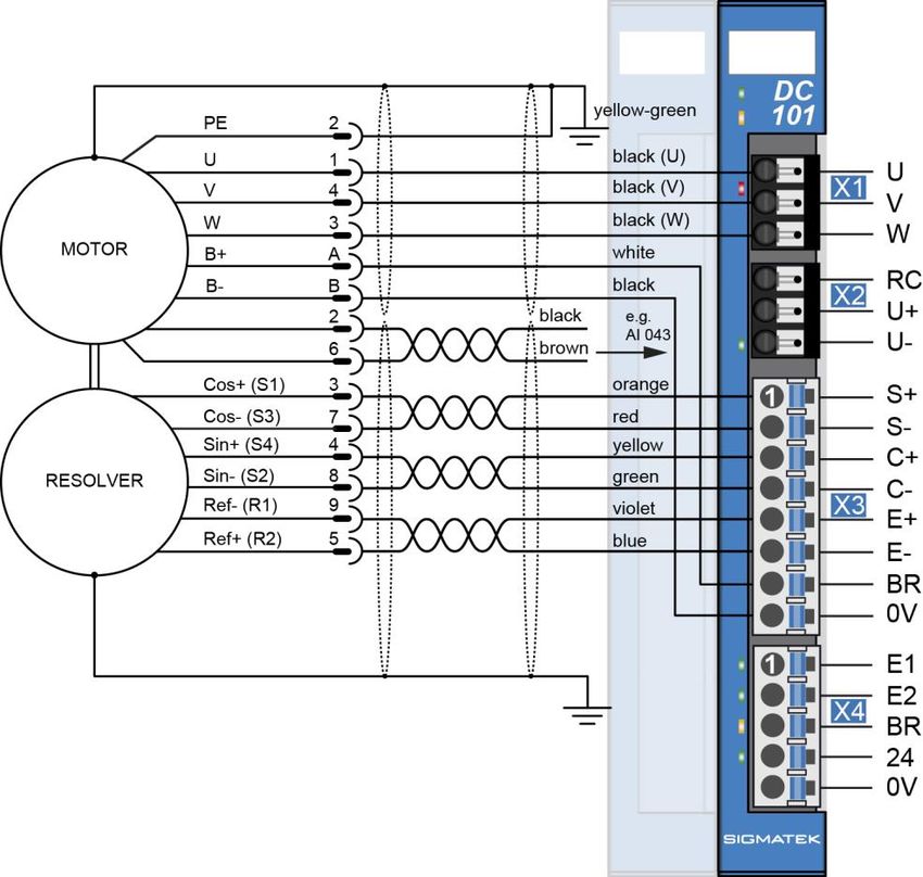
S-DIAS DRIVE MODULE     DC 101

S-DIAS Drive Module                                                          DC 101

with 1 motor output stage 10 A
     1 resolver input
     1 holding brake

The S-DIAS DC 101 drive module is used to control a synchro-
nous servo motor with a 48-Volt supply voltage and phase current
of up to 10 A. A resolver input is available for position feedback. A
24 V output for connecting a holding brake is provided. External
Regen brake can also be connected.

20.01.2020                                                                     Page 1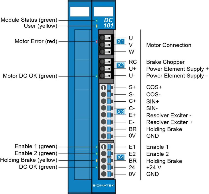
DC 101       S-DIAS DRIVE MODULE

Contents
1    Introduction ............................................................................. 5
     1.1        Target Group/Purpose of this Manual ........................................ 5

     1.2        Contents of Delivery ..................................................................... 5

2    Basic Safety Guidelines ......................................................... 6
     2.1        Symbols Used ............................................................................... 6

     2.2        Disclaimer ...................................................................................... 8

     2.3        General Safety Guidelines ........................................................... 9

3    Technical Data .......................................................................10
     3.1        DC Motor Output Specifications ............................................... 10

     3.2        Resolver Specifications ............................................................. 10

     3.3        Enable Input Specifications ....................................................... 11

     3.4        Holding Brake Specifications .................................................... 11

     3.5        Regen Brake Specifications ...................................................... 12

     3.6        Electrical Requirements ............................................................. 13

     3.7        Miscellaneous ............................................................................. 16

     3.8        Environmental Conditions ......................................................... 16

4    Mechanical Dimensions ........................................................17

5    Connector Layout ..................................................................18
     5.1        Baumüller Configuration ............................................................ 18

     5.2        Kollmorgen Configuration ......................................................... 19

     5.3        Status LEDs ................................................................................. 20
Page 2                                                                                              20.01.2020
S-DIAS DRIVE MODULE                        DC 101

      5.4        Applicable Connectors ............................................................... 21

      5.5        Label Field ................................................................................... 23

6    Wiring ..................................................................................... 24
      6.1        Wiring Example ........................................................................... 24

      6.2        Motor cable AKM......................................................................... 25

7    Motor overload Protection .................................................... 26

8    Safety Conformity ................................................................. 26
      8.1        Guidelines .................................................................................... 26

      8.2        Norms Used for Functional Safety ............................................ 26

      8.3        EU Declaration of Conformity .................................................... 26

      8.4        Safety-Relevant Parameters ...................................................... 27

9    Additional Safety Information .............................................. 28
      9.1        STO ............................................................................................... 32

      9.2        Function ....................................................................................... 32

10   Wiring Examples ................................................................... 34
      10.1       Performance Level e, Category 4 or SIL 3 – Safety PLC ........ 34

      10.2       Performance Level e, Category 3 or SIL 3 – Safety PLC ........ 35

      10.3       Performance Level e, Category 4 or SIL 3 – Conventional ..... 38

      10.4       Performance Level d Category 2 or SIL 2 – Conventional ..... 40

11   Transport/Storage ................................................................. 42

12   Mounting ................................................................................ 43
20.01.2020                                                                                                   Page 3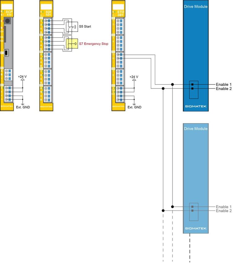
DC 101       S-DIAS DRIVE MODULE

13   Maintenance ...........................................................................45
     13.1        Service ......................................................................................... 45

     13.2        Repair ........................................................................................... 45

14   Disposal ..................................................................................45

Page 4                                                                                                20.01.2020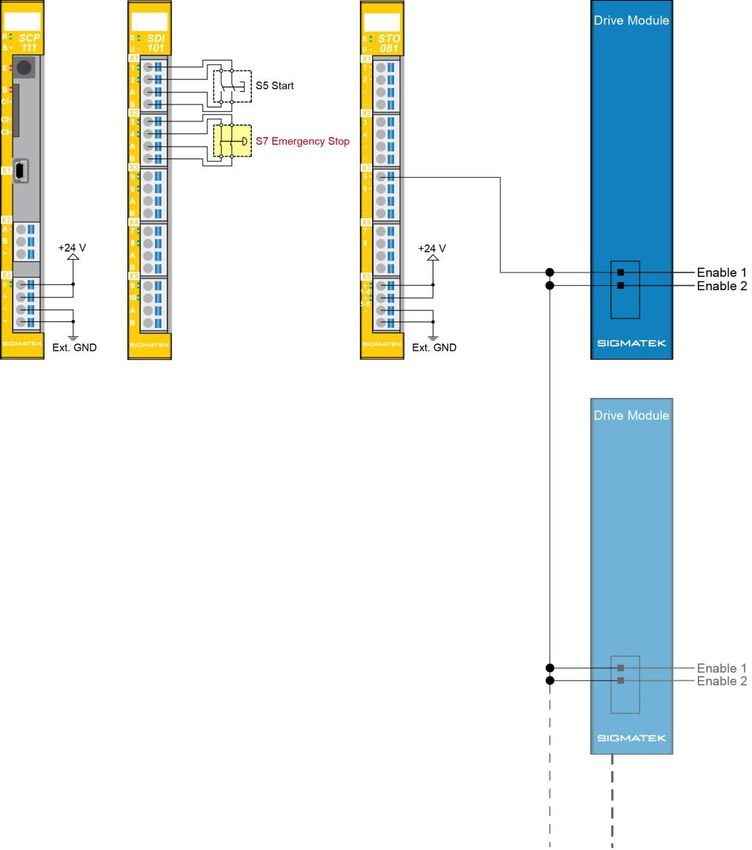
S-DIAS DRIVE MODULE           DC 101

1     Introduction
1.1       Target Group/Purpose of this Manual
This manual contains all information required to operate the DC 101

This manual is intended for:

      •    Project planners
      •    Technicians
      •    Commissioning engineers
      •    Machine operators
      •    Maintenance/test technicians

General knowledge of automation technology is required.

Further help and training information, as well as the appropriate accessories can be found
on our website www.sigmatek-automation.com

Our support team is happily available to answer your questions.
Please see our website for our hotline number and business hours.

1.2       Contents of Delivery
1x DC 101
4x opposing connectors

This document can be downloaded from our website.
Additional documents may be included with delivery.

20.01.2020                                                                         Page 5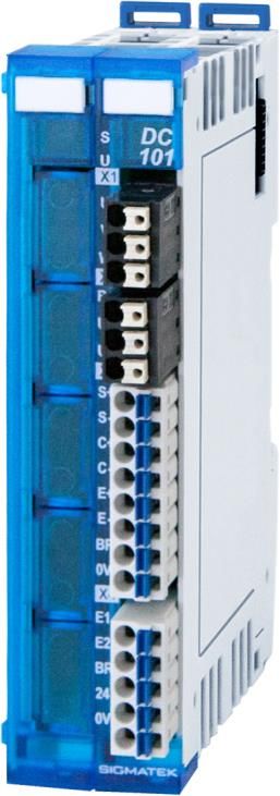
DC 101       S-DIAS DRIVE MODULE

2     Basic Safety Guidelines
2.1      Symbols Used
The following symbols are used in the operator documentation for warning and danger
messages, as well as informational notes:

DANGER        Identifies an immediate danger with high risk, which will lead to immediate
              death or serious injury if not avoided.
              Identifie un danger immédiat avec un risque élevé, entraînant le décès
              immédiat ou des blessures graves s’il n’est pas évité.

WARNING       Identifies a possible danger with a mid-level risk, which can lead to death or
              (serious) injury if not avoided.
              Indique un danger possible d’un risque moyen de décès ou de (graves)
              blessures si les consignes de sécurité ne sont pas respectées

CAUTION       Identifies a low risk danger, which can lead to injury or property damage if
              not avoided.
              Indique un danger avec un niveau de risque faible des blessures légères ou
              des dommages matériels si les consignes de sécurité ne sont pas re-
              spectées.

              Warning, dangerous electrical voltage.
              Attention, tension électrique dangereuse.

              Hot surface warning.
              Avertissement de surface chaude.

              Danger for ESD-sensitive components.
              Les signes de danger pour les composants sensibles aux décharges élec-
              trostatiques.

Page 6                                                                           20.01.2020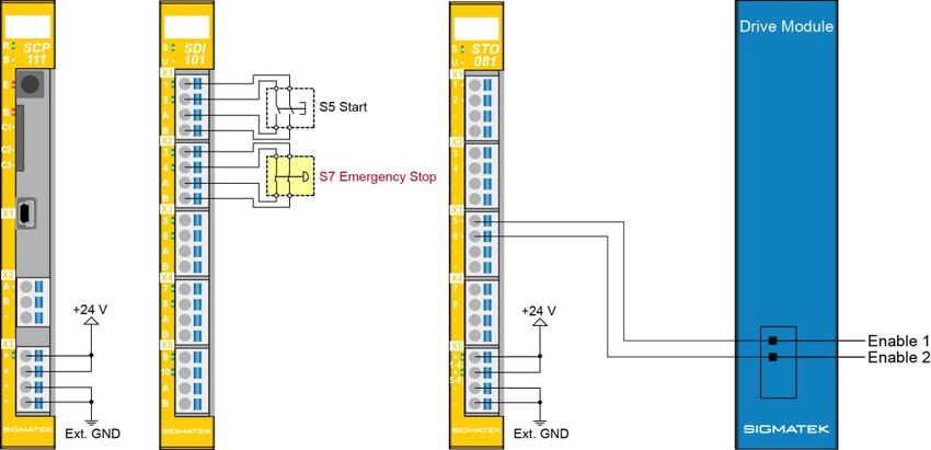
S-DIAS DRIVE MODULE             DC 101

             Provides user tips, informs of special features and identifies especially
             important information in the text.
             Fournit des conseils d’utilisation, informe sur les fonctions particulaires et
             souligne les informations particulièrement importantes dans le texte.

20.01.2020                                                                          Page 7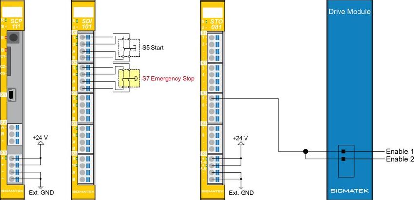
DC 101        S-DIAS DRIVE MODULE

2.2      Disclaimer

               The contents of this document were prepared with the greatest care. How-
               ever, deviations cannot be ruled out. This document is regularly checked
               and required corrections are included in the subsequent versions. The
               machine manufacturer is responsible for the proper assembly, as well as
               device configuration. The machine operator is responsible for safe han-
               dling, as well as proper operation.
               The current document can be found on our website. If necessary, contact
               our support.
               Subject to technical changes, which improve the performance of the devic-
               es. The following documentation is purely a product description. It does not
               guarantee properties under the warranty.
               Please thoroughly read the corresponding data sheets, operating instruc-
               tions and this system handbook before handling a product.
               SIGMATEK GmbH & Co KG is not liable for damages caused through
               non-compliance with these instructions or applicable regulations.
               The general and special safety instructions described in the following sec-
               tions, as well as technical regulations, must therefore be observed.

Page 8                                                                          20.01.2020
S-DIAS DRIVE MODULE DC 101
2.3 General Safety Guidelines
According to EU Guidelines, the operating instructions are a component of
a product.
This manual must therefore be accessible in the vicinity of the machine
since it contains important instructions.
This technical documentation should be included in the sale, rental or trans-
fer of the product, or its online availability indicated.
Maintain this manual in readable condition and keep it accessible for refer-
ence.
Regarding the requirements for Safety and health connected to the use of
machines, the manufacturer must perform a risk assessment in accordance
with machine guidelines 2006/42/EG before introducing a machine to the
market.
Before commissioning this product, check that conformance with the provi-
sions of the 2006/42/EG guidelines is correct. As long as the machine with
which the with the device should be used does not comply with the guide-
line, operating this product is prohibited.
Operate the unit with devices and accessories approved by SIGMATEK
only.
CAUTION Handle the device with care and do not drop or let fall.
Prevent foreign bodies and fluids from entering the device.
The device must not be opened, otherwise it could be damaged!
Manipulez l’appareil avec précaution et ne le laissez pas tomber.
Empêchez les corps étrangers et les liquides de pénétrer dans l’appareil.
L’appareil ne doit pas être ouvert, sinon il risque d’être endommagé!
20.01.2020 Page 9DC 101 S-DIAS DRIVE MODULE
3 Technical Data
3.1 DC Motor Output Specifications
Type Synchronous servo motor
Operating voltage +18-55 V
Maximum continuous current 10 A
Maximum peak current (10 s) 20 A
Output current over the environ- maximum 10 A continuous current at 45 °C
mental temperature
maximum 7.5 A continuous current at 50 °C
maximum 5 A continuous current at 55 °C
Controller frequency 16 kHz
Overload protection Short circuit cutoff
Temperature monitoring
I2t monitor
Over and under voltage monitor
CAUTION The derating, depending on the temperature, is not automatic It must be
ensured that the output current, depending on the temperature, does not
exceed the maximum values.
Le déclassement, en fonction de la température, n'est pas automatique Il
faut s'assurer que le courant de sortie, en fonction de la température, ne
dépasse pas les valeurs maximales.
3.2 Resolver Specifications
Type Resolver
Resolution 12-bit
Output voltage (EXC) typically 7 Vrms
Maximum output current (EXC) 200 mA
Output frequency 8 kHz (1)
Input voltage typically 3.5 Vrms
Resolver transfer ratio 0.5
(1)
Resolver excitation of 4 kHz is also possible. See parameter description A-ACME bit 7.
Page 10 20.01.2020S-DIAS DRIVE MODULE DC 101 3.3 Enable Input Specifications Number 2 Input voltage 24 V Input voltage range +18-30 V Signal level low: < 5 V high: > 15 V Switching threshold typically 11 V Input current 3 mA at 24 V Input delay typically 0.5 ms 3.4 Holding Brake Specifications Output voltage 24 V Maximum continuous current 500 mA Short-circuit protection yes 20.01.2020 Page 11
DC 101               S-DIAS DRIVE MODULE

3.5          Regen Brake Specifications

      Type                                                       External power resistor

      Output                                                         GND switching

      Maximum current                                                    10 A (1)

      Lowest possible resistance                                          6 Ω (2)

      Short-circuit protection                                             yes

      Regen resistor switching thresh-                                  60 V/55 V
      old on/off

(1)
    Regen braking must be dimensioned according to the application For most applications, a 10 Ω /50 W resistor is
sufficient. If multiple DC 101s are driven with a single DC-Line supply, it is possible to equip only one module with
regen braking. The recommended regen resistor (15 Ω /100 W) is available at SIGMATEK under the article number
20-014-061-Z1.
(2)
   The resistance must be dimensioned based on its maximum power dissipation corresponding to the braking power
generated in the application. However, the permissible short-term power generated must be at least P=U2/R, meaning
602/R.

                      Hot surface warning!
                      Physical contact poses a burn hazard!
                      During operation, the surface of the brake resistor can become very hot and
                      remain so for some time after operation.
                      Avertissement de surface chaude
                      Le contact physique pose un risque de brûlure
                      Pendant le fonctionnement, la surface de la résistance de freinage peut
                      devenir très chaude et le rester pendant un certain temps après le fonction-
                      nement.
                      Avoid physical contact with the surface of the brake resistor, and for a sig-
                      nificant time after operation as well.
                      Eviter tout contact physique avec la surface de la résistance de freinage,
                      ainsi que pendant une longue période après le fonctionnement.

Page 12                                                                                               20.01.2020
S-DIAS DRIVE MODULE DC 101
3.6 Electrical Requirements
Power supply +24 V +18-30 V, Class 2 (1)
Current consumption of +24 V load-dependent (holding brake)
power supply
Supply voltage Motor +18-55 V (2)
Switching threshold for minimum 18 V maximum 65 V
motor voltage monitor
Current consumption of motor load-dependent (motor)
supply
Voltage supply from S-DIAS bus +24 V
Current consumption on the S- typically 95 mA maximum 110 mA
DIAS bus (+24 V supply)
(1) For USA and Canada:
The supply must be limited to:
a) max. 5 A at voltages from 0-20 V DC, or
b) 100 W at voltages from 20-60 V DC.
The limiting component (e.g. transformer, power supply or fuse) must be certified by an
NRTL (Nationally Recognized Testing Laboratory).
(2)
The motor supply must be connected with an appropriate DC-link capacitance (at least
2000 µF / 100 V).
Braking a DC motor
When braking a DC motor, a generative process can occur whereby the
kinetic energy of the motor is converted into electrical energy. The energy
of the motor is thereby fed back into the supply of the DC motor output
stage; this then increases the supply voltage. It should be noted that the
feedback voltage supply cannot exceed 65 V! The external capacity of the
motor supply may be needed. If the capacitors in the power supply are
insufficient, a regen resistor, which converts the excess energy into heat,
must be connected to the DC motor output stage. When selecting the pow-
er supply, it is important to ensure that it is sufficiently feedback-resistant up
to the maximum feedback voltage.
Use only conductors, which are rated for at least 75 °C!
There is no motor thermostat analysis in the motor output.
20.01.2020 Page 13DC 101 S-DIAS DRIVE MODULE
Incorrectly set parameters or incorrect wiring can lead to destruction of the
motor. It is important that the motor currents and the I 2T settings (A-I2TT, A-
I2TERR), which can be defined via the LASAL Class 2 Tool in the DIAS-
Drive Editor, be taken into account.
Only motors in a star configuration can be used.
Page 14 20.01.2020S-DIAS DRIVE MODULE DC 101 20.01.2020 Page 15
DC 101             S-DIAS DRIVE MODULE

3.7    Miscellaneous

  Article number                                                  20-014-101

  Hardware version                                                    1.x

  Standard                                            CE, TÜV EG type testing in process

3.8    Environmental Conditions

  Storage temperature                                            -20 ... +85 °C

  ambient temperature                                             0 ... +55 °C

  Humidity                                                   0-95 %, non-condensing

  Installation altitude above sea                          0-2000 m without derating
  level
                                    > 2000 m with derating of the maximum environment temperature by 0.5 °C
                                                                    per 100 m

  Operating conditions                                         pollution degree 2

  EMC resistance                      in accordance with EN 61000-6-7:2015 (Generic standards – immunity
                                    requirements for equipment designed to perform functions in safety-based
                                                 systems (functional safety) at industrial facilities)

                                            according to EN 61000-6-2:2005/AC:2005 (industrial area)
                                             (increased requirements in accordance with IEC 62061)

                                     additionally tested according to EN 61800-5-2:2017 (Generic Standard –
                                    Electrical Power Drive Systems with Adjustable Speed Section 5-2: Safety
                                                         Requirements – Functional Safety)

  EMC noise generation                      according to EN 61000-6-4:2007/A1:2011 (industrial area)

  Vibration resistance                        EN 60068-2-6                        3.5 mm from 5-8.4 Hz
                                                                                   1 g from 8.4-150 Hz

  Shock resistance                           EN 60068-2-27                               15 g

  Protection type                               EN 60529                                 IP20

Page 16                                                                                          20.01.2020
S-DIAS DRIVE MODULE DC 101 4 Mechanical Dimensions 20.01.2020 Page 17
DC 101      S-DIAS DRIVE MODULE

5     Connector Layout
5.1    Baumüller Configuration

             Both holding brake outputs (BR) are internally connected in parallel. The
             holding brake can therewith be optionally wired to X3 (pin 7-pin 8) or X4
             (pin 3-GND).
             The configuration results in an M-ROFF of 270.

Page 18                                                                    20.01.2020
S-DIAS DRIVE MODULE DC 101
5.2 Kollmorgen Configuration
Both holding brake outputs (BR) are internally connected in parallel. The
holding brake can therewith be optionally wired to X3 (pin 7-pin 8) or X4
(pin 3-GND).
20.01.2020 Page 19DC 101 S-DIAS DRIVE MODULE
5.3 Status LEDs
Module Status green ON module active
OFF no supply available
BLINKING (5 Hz) no communication
User yellow ON can be set from the application
OFF (e.g. the module LED can be set to blinking through the visuali-
zation so that the module is easily found in the control cabinet)
BLINKING (2 Hz)
BLINKING (4 Hz)
Motor Error red BLINKS motor output stage error
OFF normal operation
Motor DC OK green ON power applied and motor active
OFF no motor supply voltage
BLINKS power applied, but motor inactive
ENABLE 1 green ON Enable 1 high
OFF Enable 1 low
ENABLE 2 green ON Enable 2 high
OFF Enable 2 low
Holding brake yellow ON output active
OFF output inactive
DC OK green ON +24 V supply ok
OFF +24 V missing or voltage too low
BLINKS +24 V voltage supply too high
Page 20 20.01.2020S-DIAS DRIVE MODULE DC 101
5.4 Applicable Connectors
X1, X2: Weidmüller socket connectors with spring terminals (included in delivery)
X3, X4: Phoenix connector plugs with spring terminals (included in delivery)
The spring terminals are suited for the connection of ultrasonically compacted (ultrasonical-
ly welded) stranded wire.
Weidmüller connection capacity:
Stripping length/sleeve length. 9 mm
Mating direction: parallel to the conductor axis or circuit board
Conductor cross section rigid: H05(07) V-U 0.14-1.5 mm2
Conductor cross section flexible: H05(07) V-K 0.14-1.5 mm2
Conductor cross-section strands ultrasonically compacted: 0.14-1.5 mm2
Conductor cross section AWG/kcmil: 26-16
Conductor cross section flexible with ferrule without plastic 0.25-1.5 mm2
sleeve (DIN 46228-1):
Conductor cross section flexible with ferrule with plastic sleeve 0.25-1 mm2 (reason for reduction d2 of the
(DIN 46228-4): ferrule)
Phoenix connection capacity:
Stripping length/sleeve length. 10 mm
Mating direction: parallel to the conductor axis or circuit board
Conductor cross section rigid: 0.2-1.5 mm2
Conductor cross section flexible: 0.2-1.5 mm2
Conductor cross-section strands ultrasonically compacted: 0.2-1.5 mm2
Conductor cross section AWG/kcmil: 24-16
Conductor cross section flexible with ferrule without plastic 0.25-1.5 mm2
sleeve:
Conductor cross section flexible with ferrule with plastic sleeve: 0.25-0.75 mm2 (reason for reduction d2 of the
ferrule)
20.01.2020 Page 21DC 101 S-DIAS DRIVE MODULE
CAUTION The S-DIAS module CANNOT be connected/disconnected while voltage is
applied!
Le module S-DIAS ne peut pas être inséré ou retiré sous tension !
Page 22 20.01.2020S-DIAS DRIVE MODULE DC 101 5.5 Label Field Manufacturer Weidmüller Type MF 10/5 CABUR MC NE WS Article number Weidmüller 1854510000 Compatible printer Weidmüller Type Printjet Advanced 230V Article number Weidmüller 1324380000 20.01.2020 Page 23
DC 101      S-DIAS DRIVE MODULE

6     Wiring
6.1    Wiring Example

Page 24                           20.01.2020
S-DIAS DRIVE MODULE   DC 101

6.2   Motor cable AKM
with SIGMATEK resolver and AKM motor cable

20.01.2020                                                         Page 25
DC 101          S-DIAS DRIVE MODULE

7         Motor overload Protection
The device has no integrated motor overload protection. Please take using suitable protec-
tion in accordance with local specifications into consideration with your installation. This can
be implemented with a limiting supply, a fuse or something similar.

For an installation according to UL specifications (USA and Canada), external overload
protection in accordance with the National Electrical code (NEC) must be installed and all
corresponding guidelines followed.

8         Safety Conformity
8.1        Guidelines
The panel was constructed in compliance with European Union guidelines.

8.2        Norms Used for Functional Safety
      -     EN / IEC 62061:2005/A2 2015
      -     EN ISO 13849-1:2015
      -     EN ISO 13849-2:2012

8.3        EU Declaration of Conformity

                 CE Declaration of Conformity
                 The DC 101 conforms to the following European guidelines:
                     •   2006/42/EG Machine Guideline
                     •   2014/30/EU “Electromagnetic Compatibility” (EMC guideline)
                     •   2011/65/EU “Restricted use of certain hazardous substances in
                         electrical and electronic equipment” (RoHS Guideline)
                 The EU Conformity Declarations are provided on the SIGMATEK website.
                 Using the search function with the keyword “EU Declaration of Conformity”.

Page 26                                                                             20.01.2020
S-DIAS DRIVE MODULE DC 101
8.4 Safety-Relevant Parameters
DC 101 Safety Parameters Safety Level
Safety Function STO PFHD = 1.93E-09 (1/h) SIL 3 according to EN/IEC
62061
MTTFd = 1194 years
PL e / Cat. 4
DC = 98.35 % According to EN ISO 13849-1/-2
SFF = 99.90 %
20.01.2020 Page 27DC 101 S-DIAS DRIVE MODULE
9 Additional Safety Information
The Safety function “STO” is an integrated component of the DC motor output stage. It
meets all necessary requirements for safe operation in SIL 3 according to EN 62061 and in
compliance with PL e. Cat. 4 in accordance with EN ISO 13849-1/-2.
CAUTION The instructions contained in this document must be followed.
The DC 101 can only be powered by supplies that meet the requirements
for SELV or PELV in compliance with EN 60204.
For error-free operation, proper transport and storage are essential. See
chapter 2 for more information.
Installation, mounting, programming, initial start-up, operation, maintenance
and decommissioning can only be performed by qualified personnel.
Qualified personnel in this context are people, who have completed training
or have trained under supervision of qualified personnel and have been
authorized to operate and maintain safety-related equipment, systems and
facilities in compliance with the strict guidelines and standards of safety
technology. The applicable environmental conditions must be maintained.
Les instructions contenues dans ce document doivent être suivies.
Le DC 101 ne peut être alimenté que par des alimentations répondant aux
exigences SELV ou PELV selon EN 60204.
Pour un fonctionnement sans erreur, le transport et le stockage appropriés
sont essentiels. Voir le chapitre 8 pour plus d’informations.
L’installation, le montage, la programmation, la mise en service initiale,
l’exploitation, la maintenance et la mise hors service ne peuvent être effec-
tués que par une personne qualifiée.
Dans ce contexte, on entend par personnel qualifié les personnes qui ont
suivi une formation ou qui ont été formées sous la supervision d’un person-
nel qualifié et qui ont été autorisées à utiliser et à entretenir l’équipement,
les systèmes et les installations de sécurité conformément aux directives et
aux normes strictes de la technique de sécurité. Les conditions envi-
ronnementales applicables doivent être respectées.
Page 28 20.01.2020S-DIAS DRIVE MODULE DC 101
For your own safety and that of others, the safety modules should be used
for their designated purpose only.
Correct EMC installation is also included in the designated use.
Pour votre propre sécurité et celle des autres, les modules de sécurité ne
doivent être utilisés qu’à des fins prévues.
Une installation CEM correcte est également incluse dans l’utilisation pré-
vue
Non-designated use consists of:
• any changes made to the module or the use of damaged modules.
• use of the module inconsistent with the technical margins de-
scribed in this manual or the speciation's defined in the technical
data (see chapter Fehler! Verweisquelle konnte nicht gefunden w
erden.).
L'utilisation non désignée consiste en:
• toute modification apportée au module ou l'utilisation des modules
endommagés.
• utilisation du module non conforme aux marges techniques dé-
crites dans ce manuel ou aux spécifications définies dans les don-
nées techniques (voir chapitre 4).
20.01.2020 Page 29DC 101 S-DIAS DRIVE MODULE
DANGER Failure to follow the above safety measures can lead to severe injuries.
Le non-respect des mesures de sécurité ci-dessus peut entraîner des
blessures graves.
• Only trained personnel are authorized to install the "safe
restart lock" STO (Safe Torque off) and set the parame-
ters.
• All control devices (switches, relays, PLC, etc.) and the
control cabinet must meet the requirements for EN 13849
This consists of:
– Door switches, etc. with at least IP54 protection.
– Control cabinet with at least IP54 protection.
• The proper cables and end-sleeves must be used
• All cables that affect safety (e.g. control cables for the
ENABLE 1 and ENABLE 2 inputs) must be laid in a cable
duct outside of the control cabinet. Short or crossed cir-
cuits in the signal lines must be avoided! See EN ISO
13849
• If external forces influence axes that are used with the
STO safety function (e.g. hanging load), additional
measures must be taken (such as an electromagnetic
double-surface spring brake, instead of a permanent
magnet brake).
• Seul un personnel qualifié est autorisé à installer le
"blocage de redémarrage sûr" STO (Safe Torque off) et à
régler les parameters.
• Tous les appareils de commande (interrupteurs, relais,
API, etc.) et l'armoire de commande doivent satisfaire
aux exigences de la norme EN 13849:
- Interrupteurs de porte, etc. avec au moins un in
dice de protection IP54.
- Classes de contrôle avec au moins un indice de pro-
tection IP54.
• Les câbles et les embouts appropriés doivent être utili-
sés.
• Tous les câbles affectant la sécurité (par ex. les câbles
de commande pour les entrées ENABLE 1 et ENABLE 2)
doivent être posés dans un conduit de câbles de raccor-
dement à l'extérieur de l'armoire électrique. Eviter les
courts-circuits ou les courts-circuits croisés dans les
Page 30 20.01.2020S-DIAS DRIVE MODULE DC 101
lignes de signalisation ! Voir EN ISO 13849
• Si des forces externes influencent les axes utilisés avec
la fonction de sécurité STO (par ex. charge suspendue),
des mesures supplémentaires doivent être prises (par ex.
un frein à ressort électromagnétique à double surface au
lieu d'un frein à aimant permanent).
CAUTION The main power supply for the servo amplifier must be disconnected using
the main switch for the following instances:
• Cleaning, maintenance or repairs
• Extended still-stand periods
L'alimentation principale du variateur doit être débranchée à l'aide de l'inter-
rupteur principal dans les cas suivants :
• Nettoyage, entretien ou réparation
• Périodes d'immobilisation prolongées
Hot surface warning!
Physical contact poses a burn hazard!
With unfavorable installation and operating conditions, the surface of the S-
DIAS drive module can reach temperatures up to 84 °C and remain hot for
some time after operation.
Avertissement de surface chaude !
Le contact physique présente un risque de brûlure !
En cas de conditions d'installation et de fonctionnement défavorables, la
surface du module d'entraînement S-DIAS peut atteindre des températures
allant jusqu'à 84 °C et rester chaude pendant un certain temps après utili-
sation.
20.01.2020 Page 31DC 101 S-DIAS DRIVE MODULE
9.1 STO
The DC 101 supports the safety functions STO (Safe Torque Off) and meets the require-
ments for Category 4 Performance Level "e" according to EN ISO 13849-1 and SIL3 ac-
cording to EN / IEC 62061.
For this purpose, the servo amplifier has two safe inputs ENABLE 1 and ENABLE 2.
The holding brake control is not a component of the safety function. If a safe shutdown of
the holding brake is required, the +24 V-BR brake supply must also be shut down external-
ly.
9.2 Function
The safety functions in the DC 101 are controlled over two digital inputs.
The following table shows the status that the safe inputs ENABLE 1 and ENABLE 2 must
assume to allow normal operation or trigger the safety function.
Input Status Description
ENABLE 1 ENABLE 2
Open Open Safe status of the drive system
Open Low
Low Open
Low Low
Low High
High Low
High High Drive system ready
If the ENABLE 1 and ENABLE 2 inputs are changed from any status to the "Drive Ready"
status, the servo amplifier is not immediately enabled. In order to set the system to “Drive
system ready” status, a change from “Low - Low” to “High - High” must occur. The reason
for this is, for example, welded contacts are detected by switching devices.
Page 32 20.01.2020S-DIAS DRIVE MODULE DC 101
9.3 Function Test
WARNING The safety function test is required to ensure correct operation. The entire
safety circuit must be tested for full functionality.
Tests must be performed at the following times:
• After installation
• In regular intervals, or at least once a year.
If the function test results in an invalid machine status, the error must be
found and corrected before the safety function is retested. If the error reoc-
curs during the function test, the machine can no longer be operated.
Le test de fonctionnement de sécurité est nécessaire pour garantir un
fonctionnement correct. L'ensemble du circuit de sécurité doit être testé
pour s'assurer de son bon fonctionnement.’
Les essais doivent être effectués aux moments suivants:
• Après l'installation
• A intervalles réguliers, ou au moins une fois par an
Si le test de fonctionnement aboutit à un état machine non valide, l'erreur
doit être détectée et corrigée avant que la fonction de sécurité ne soit de
nouveau testée. Si l'erreur se reproduit pendant le test de fonctionnement,
la machine ne peut plus être utilisée.
20.01.2020 Page 33DC 101 S-DIAS DRIVE MODULE 10 Wiring Examples In the following sub chapters, wiring examples are provided. It must be ensured that all constructive measures etc. are taken and applied in order to fulfill the requirements of the category used. 10.1 Performance Level e, Category 4 or SIL 3 – Safety PLC To meet the requirements of category 4, performance Level "e" for EN ISO 13849-1 and SI L 3 according to EN / IEC 62061, two error-proof output of a Safety PLC must be used. Cross-circuit detection between the two lines via the output tests of the STO 081 is hereby possible. Page 34 20.01.2020
S-DIAS DRIVE MODULE          DC 101

10.2 Performance Level e, Category 3 or SIL 3 – Safety PLC
To meet the requirements of safety category 3, performance level "e" for EN ISO 13849-1
and SIL 3 according to EN / IEC 62061, an error-proof output of a safety PLC must be

20.01.2020                                                                    Page 35
DC 101        S-DIAS DRIVE MODULE

used. The reason for category 3 here, is that cross-circuit detection between the two lines is
not possible.

Page 36                                                                           20.01.2020
S-DIAS DRIVE MODULE   DC 101

20.01.2020                         Page 37
DC 101        S-DIAS DRIVE MODULE

10.3 Performance Level e, Category 4 or SIL 3 – Conventional
To meet the requirements of safety category 4, performance level "e" for EN ISO 13849-1
and SIL 3 according to EN /IEC 62061, the placement of the lines must comply with EN ISO
13849-2, table D.4 (separate placement, prohibiting short circuits between wires) as cross-
circuit detection is not possible here.

Page 38                                                                        20.01.2020
S-DIAS DRIVE MODULE   DC 101

20.01.2020                         Page 39
DC 101       S-DIAS DRIVE MODULE

10.4 Performance Level d Category 2 or SIL 2 – Conventional
This involves 1-channel wiring, whereby the Enable inputs are tested separately. Here, no
cross-circuit detection is possible.

Page 40                                                                      20.01.2020
S-DIAS DRIVE MODULE   DC 101

20.01.2020                         Page 41
DC 101    S-DIAS DRIVE MODULE

11 Transport/Storage
          This device contains sensitive electronics. During transport and storage,
          high mechanical stress must therefore be avoided.
          For storage and transport, the same values for humidity and vibration as for
          operation must be maintained!

CAUTION   During transport, temperature and humidity fluctuations may occur. Ensure
          that no moisture condenses within or on the device.
          Pendant le transport, des fluctuations de température et d'humidité peuvent
          survenir. Veillez à ce qu'il n'y ait pas de condensation d'humidité dans ou
          sur l'appareil.

Page 42                                                                     20.01.2020
S-DIAS DRIVE MODULE DC 101 12 Mounting The S-DIAS modules are designed for installation into the control cabinet. To mount the modules, a DIN-rail is required. The DIN rail must establish a conductive connection with the back panel of the control cabinet. The individual S-DIAS modules are mounted on the DIN rail as a block and secured with latches. The modules must be mounted horizontally (module label up) with sufficient clearance between the ventilation slots of the S-DIAS mod- ule blocks and nearby components and/or the control cabinet panel. This is necessary for optimal cooling and air circulation, so that proper function up to the maximum operating temperature is ensured. 20.01.2020 Page 43
DC 101       S-DIAS DRIVE MODULE

Recommended minimum distances of the S-DIAS modules to the surrounding components
or control cabinet wall:

a, b, c … distances in mm (inches)

Page 44                                                                20.01.2020
S-DIAS DRIVE MODULE            DC 101

13 Maintenance
WARNING        During maintenance as well as servicing, observe the safety instructions
               from chapter 1.
               Lors de l'entretien et de la maintenance, respectez les consignes de sécu-
               rité du chapitre 2.

13.1 Service
This product was constructed for low-maintenance operation.

13.2 Repair

               When sent for repair, the panel should be transported in the original pack-
               aging if possible. Otherwise, packaging should be selected that sufficiently
               protects the product from external mechanical influences. Such as card-
               board filled with air cushioning.

In the event of a defect/repair, send the panel with a detailed error description to the ad-
dress listed at the beginning of this document.

14 Disposal
              When disposing of the panel, the national electronic scrap regu-
              lation must be observed.
              The panel cannot be discarded with domestic waste.

20.01.2020                                                                         Page 45
DC 101 S-DIAS DRIVE MODULE
Documentation Changes
Change date Affected page(s) Chapter Note
20.01.2020 10 3.2 Resolver Specifications Output frequency changed
25 6.2 Motor cable AKM Heading changed
Page 46 20.01.2020You can also read