Dell EMC PowerEdge R240 - Technical Guide
←
→
Page content transcription
If your browser does not render page correctly, please read the page content below
Dell EMC PowerEdge R240
Technical Guide

Regulatory Model: E57S Series
Regulatory Type: E57S001
June 2021
Rev. A03
Notes, cautions, and warnings

     NOTE: A NOTE indicates important information that helps you make better use of your product.

     CAUTION: A CAUTION indicates either potential damage to hardware or loss of data and tells you how to avoid
     the problem.

     WARNING: A WARNING indicates a potential for property damage, personal injury, or death.

© 2018 2021 Dell Inc. or its subsidiaries. All rights reserved. Dell, EMC, and other trademarks are trademarks of Dell Inc. or its subsidiaries.
Other trademarks may be trademarks of their respective owners.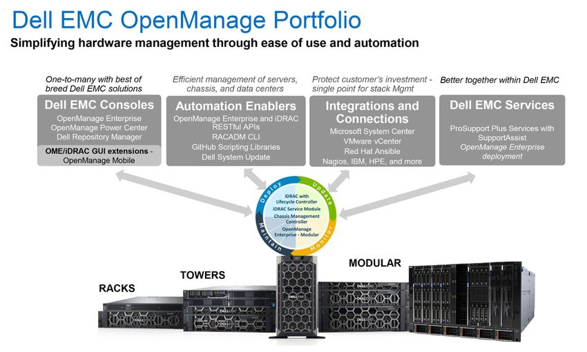
Contents

Chapter 1: Product overview......................................................................................................... 5
  Introduction...........................................................................................................................................................................5
  New technologies................................................................................................................................................................ 5

Chapter 2: System features...........................................................................................................7
  Product comparison............................................................................................................................................................ 7
  Product specifications........................................................................................................................................................8

Chapter 3: Chassis views and features......................................................................................... 11
  Front view of the system..................................................................................................................................................11
  Rear view of the system.................................................................................................................................................. 12
  Inside the system............................................................................................................................................................... 13
  Locating the information tag of your system..............................................................................................................14

Chapter 4: Processor................................................................................................................... 16
  Processor features............................................................................................................................................................ 16
  Supported processors.......................................................................................................................................................16
  Chipset..................................................................................................................................................................................17

Chapter 5: Memory...................................................................................................................... 19

Chapter 6: Storage...................................................................................................................... 21
  Supported drives................................................................................................................................................................ 21
  Storage controller specifications....................................................................................................................................21
  Optical Drives......................................................................................................................................................................21
  Tape Drives..........................................................................................................................................................................21
  Internal Dual SD Module.................................................................................................................................................. 22

Chapter 7: Networking and PCIe..................................................................................................23

Chapter 8: Power, thermal, and acoustics................................................................................... 24
  Power supply units............................................................................................................................................................24
  Thermal................................................................................................................................................................................ 24
  Acoustics............................................................................................................................................................................. 25

Chapter 9: Supported operating systems.....................................................................................27

Chapter 10: Dell EMC OpenManage systems management........................................................... 28
  Server and Chassis Managers........................................................................................................................................29
  Dell EMC consoles.............................................................................................................................................................29
  Automation Enablers........................................................................................................................................................ 29
  Integration with third-party consoles...........................................................................................................................29
  Connections for third-party consoles.......................................................................................................................... 29

                                                                                                                                                               Contents                    3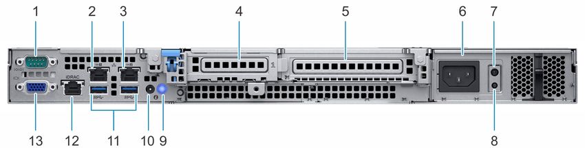
Dell EMC Update Utilities................................................................................................................................................ 29
         Dell resources.....................................................................................................................................................................29

    Chapter 11: Appendix A. Additional specifications........................................................................ 31
      Technical specifications....................................................................................................................................................31
         Chassis dimensions...................................................................................................................................................... 31
         Chassis weight............................................................................................................................................................. 32
         Video specifications.................................................................................................................................................... 32
         USB ports specifications........................................................................................................................................... 32
         Drives..............................................................................................................................................................................32
         NIC ports specifications.............................................................................................................................................33
         Environmental specifications.................................................................................................................................... 33

    Chapter 12: Appendix B. Standards compliance........................................................................... 36

    Chapter 13: Appendix C Additional resources............................................................................... 37

    Chapter 14: Appendix D. Support and deployment services..........................................................38
      Dell EMC ProDeploy Enterprise Suite ......................................................................................................................... 38
         Dell EMC ProDeploy Plus...........................................................................................................................................39
         Dell EMC ProDeploy....................................................................................................................................................39
         Dell EMC Basic Deployment......................................................................................................................................39
         Dell EMC Residency Services...................................................................................................................................39
      Deployment services........................................................................................................................................................ 39
      Dell EMC Remote Consulting Services........................................................................................................................ 39
      Dell EMC Data Migration Service..................................................................................................................................39
      ProSupport Enterprise Suite.......................................................................................................................................... 39
      ProSupport Plus................................................................................................................................................................ 40
      ProSupport......................................................................................................................................................................... 40
      ProSupport One for Data Center................................................................................................................................... 41
      Support Technologies....................................................................................................................................................... 41
      Additional professional services.....................................................................................................................................42
      Dell Education Services....................................................................................................................................................42
      Dell EMC Global Infrastructure Consulting Services................................................................................................ 42
      Dell EMC Managed Services.......................................................................................................................................... 42

4   Contents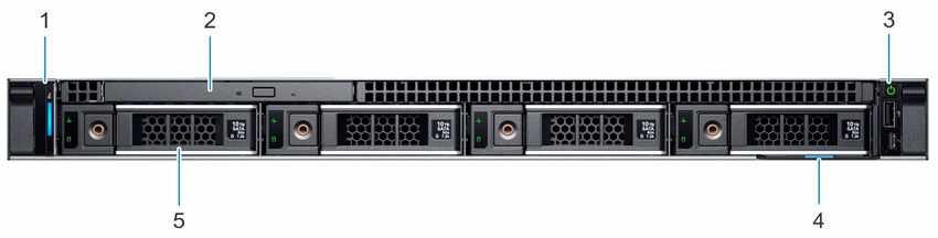
1
                                                                                 Product overview
The Dell EMC PowerEdge R240 is an affordable entry-level, single-socket 1U rack server for SMB and service providers.
The PowerEdge R240 includes four DIMM slots, supports up to 64GB UDIMMs and four 3.5-inch hard drives. The PowerEdge
R240 is ideal for web hosting, mail serving, file and print, as well as a wide range of general-purpose productivity applications.

Figure 1. Dell EMC PowerEdge R240

Topics:
•      Introduction
•      New technologies

Introduction
The PowerEdge R240 is versatile enough to address many customer segments and workloads. In particular, the PowerEdge
R240 will be best suited for applications and workloads where high availability features are not important within the server node
or where redundancy is built at the rack level. Workload targets include:
● Web serving and hosting
● Mail server
● File and Print
● SAN proxy server
● DHCP server
● Surveillance & Security
● Wide variety of mainstream business applications

New technologies
The following table shows the list of new technologies offered by the PowerEdge R240:

    New Technologies                                               Detailed Descriptions
    Intel® C246 series chipset                                     Intel Platform Controller Hub (PCH)
    Intel® Xeon® processor E- 2100 and E-2200 Product              The Intel® Xeon® E-2100 and E-2200 processors have
    Family                                                         increased core count and embedded PCIe lanes that will
                                                                   improve the IO performance and a lot more features. Please
                                                                   refer to section 4, Processors for details.
    Next Generation SW RAID, PERC S140                             The new 1-socket servers support the latest S140 software
                                                                   RAID along with H330 and H730P controller cards with
                                                                   improved functionality and faster performance. New SW RAID
                                                                   supports RAID 0, 1, 5 and 10. Please refer to section 6, for
                                                                   additional details.
    iDRAC 9                                                        The new embedded system management solution for Dell
                                                                   EMC server features hardware and firmware inventory and
                                                                   alerting, in depth memory alerting, faster performance,
                                                                   dedicated gigabit port, email alerts, electronic licensing,

                                                                                                        Product overview             5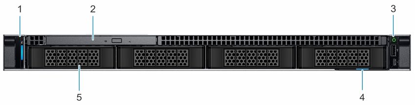
New Technologies         Detailed Descriptions
                         editable user work notes log and more. Dedicated iDRAC
                         Direct microUSB port improves at-the-box management.
                         Please refer to section 13, for additional details.

6     Product overview
2
                                                                                 System features
Topics:
•      Product comparison
•      Product specifications

Product comparison
The following table shows the comparison between the PowerEdge R230 and PowerEdge R240:

Table 1. Product comparison with predecessor
    Feature                  PowerEdge R230                                  PowerEdge R240
    Processor                ●   Intel   Xeon® E3-1200 v6 Processor family   ● Intel Xeon® E-2100 and E-2200 Processor
                             ●   Intel   Pentium®                              family
                             ●   Intel   Celeron®                            ● Intel Pentium®
                             ●   Intel   Core i3®                            ● Intel Celeron®
                                                                             ● Intel Core i3®
    Number of processors     ● 1                                             ● 1
    Number or cores          ● Up to 4 cores                                 ● Up to 8 cores
    L2/L3 cache              ● 2.0 MB per core                               ● 2.0 MB per core
                             ● 4 MB or 8 MB                                  ● 8 MB or 12 MB
    Chipset                  ● Intel C236                                    ● Intel C246
    Memory Module            ●   DDR4: 4 x UDIMMs with ECC                   ●   DDR4: 4 x UDIMMs with ECC
                             ●   Speed: Up to 2400MT/s                       ●   Speed: Up to 2666MT/s
                             ●   Min RAM: 4 GB                               ●   Min RAM: 8GB
                             ●   Max RAM: 64 GB                              ●   Max RAM: 64 GB
    Hard drive bays          ● 2 x 3.5-inch cabled                           ● 2 x 3.5-inch cabled
                             ● 4 x 3.5-inch cabled                           ● 4 x 3.5-inch cabled
                             ● 4 x 3.5-inch or 2.5-inch hot plug             ● 4 x 3.5-inch or 2.5-inch hot plug
    Hard drive types         ● Default SATA. Optional SAS                    ● Default SATA. Optional SAS
                             ● Enterprise HDD                                ● Enterprise HDD
                             ● Entry HDD                                     ● Entry HDD
    External hard drive      ● 1x slim ODD 9.5mm                             ● 1x slim ODD 9.5mm
    bays
    RAID controllers         ●   Chipset based SATA, PERC S130               ● Chipset based SATA, PERC S140
                             ●   PERC H330                                   ● PERC H330
                             ●   PERC H730                                   ● PERC H730P
                             ●   PERC H830
    Host Bus Adapter         ● 12Gb SAS External HBA                         ● 12Gb SAS Exernal HBA
    (HBA)                                                                    ● HBA330 Internal adapter
    Boot optimized storage   ● Not supported                                 ● 2x M.2 240GB (RAID 1 or No RAID)
    subsytem                                                                 ● 1x M.2 240GB (No RAID only)
    Server management        ● BMC                                           ● BMC

                                                                                                    System features      7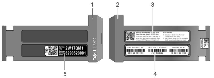
Table 1. Product comparison with predecessor (continued)
Feature                   PowerEdge R230                                         PowerEdge R240
                          ●   IPMI 2.0 compliant; Full Open Manage suite         ●   IPMI 2.0 compliant; Full Open Manage suite
                          ●   Optional iDRAC8 Express                            ●   Optional iDRAC9 Express
                          ●   Optional iDRAC8 Enterprise                         ●   Optional iDRAC9 Enterprise
                          ●   Vflash                                             ●   Vflash
I/O slots                 ● 1 x16 slot PCIe Gen3 for HL/FH from                  ● 1 x16 slot PCIe Gen3 for HL/FH from
                            CPU1(x8 lanes)                                         CPU1(x8 lanes)
                          ● 1 x 8 slot PCIe Gen3 for LP from CPU1(x4             ● 1 x 8 slot PCIe Gen3 for LP from CPU1(x4
                            lanes)                                                 lanes)
NIC/LOM                   ● 2x GbE LOM                                           ● 2x GbE LOM
USB                       ● 2 rear USB 3.0                                       ● 2 rear USB 3.0
                          ● 2 front USB 2.0                                      ● 1 front USB 2.0
                          ● 1 internal USB 3.0                                   ● 1 internal USB 3.0
Power supplies            ● 250W AC 1U cable (Bronze)                            ● 250W AC 1U cable (Bronze)
                                                                                 ● 450W AC 1U cable (Platinum)
Fans                      ● 3 or 4 non-redundant, non-hot swappable              ● 3 or 4 non-redundant, non-hot swappable
                            fans                                                   fans
Form factor               ● 1U rack                                              ● 1U rack
Dimensions (HxWxD)        ● 42.8 x 434.0 x 551 (mm) (w/o bezel)                  ● 42.8 x 434.0 x 596 (mm) (w/o bezel)
                          ● 1.67” x 17.09” x 26.2”(in)                           ● 1.67” x 17.09” x 23.5”(in)
Weight                    ● Max 20.96 lb/10.6 Kg                                 ● Max 26.89 lb/12.2 Kg

Product specifications
The following table lists the technical specifications for the PowerEdge R240:

Table 2. Technical specifications
Features                                                         Specifications
Form factor                                                      ● 1U rack
Processors                                                       ● Intel®   Xeon® processor E-2100 and E-2200 product
                                                                   family
                                                                 ● Intel®   Core™ i3
                                                                 ● Intel®   Pentium®
                                                                 ● Intel®   Celeron
Processor sockets                                                ● 1
Front Side Bus or HyperTransport                                 ● Intel DMI 3.0
Cache                                                            ● 2.0 MB per core
                                                                 ● 8 MB or 12 MB
Chipset                                                          ● Intel C246 Chipset
Memory1                                                          ● Up to 64GB (4 DIMM Slots)
                                                                 ● 8GB/16GB 2666MT/s Unbuffered with ECC only
                                                                 ● MIN/ MAX RAM: 8GB/64GB
I/O slots                                                        ● 2 GEN3 PCIe slots:
                                                                   ○ X16 slot FH (1x8 Gen3)
                                                                   ○ X8 Slot LP (1X4 Gen3)
RAID controller                                                  ● S140

8        System features
Table 2. Technical specifications (continued)
Features Specifications
● PERC H330
● PERC H730P
Host Bus Adapter (HBA) ● 12Gb SAS External HBA
● HBA330 Internal adapter
Drive bays ● Up to 4 x 3.5-inch cable drives
● Up to 4 x 3.5-inch or 2.5-inch Hot-Plug drives
Maximum internal storage ● 56.0TB for 4 x HDD config
Hard drives ● 2.5-inch SSD SATA 6Gb
● 2.5-inch SATA 7.2K
● 2.5-inch SAS 15K HDs
● 2.5-inch Near Line SAS 7.2K
● 2.5-inch SAS 10K HDDs
● 3.5-inch Enterprise SATA 7.2K HDDs
● 3.5-inch Near Line SAS 7.2K HDDs
● 3.5-inch 7.2K SATA client drives
● 2.5-inch SAS SSDs
HDDs capacities:
300GB, 600GB, 900GB, 1TB, 1.2TB, 1.8TB, 2TB, 2.4TB, 4TB,
6TB, 8TB, 10TB, 12TB, 14TB
SSD capacities:
240GB, 480GB, 960GB, 1.2TB, 1.6TB, 1.92TB, 3.84TB, and
7.68TB
Embedded LOM/NIC ● Integrated BROADCOM BCM5720 Gigabit Ethernet
Controller
Communications Optional add-in cards:
● 1GbE Intel (Dual) Powerville Troi-Stony Dual port 1Gb
Base-T adapter – FH or LP
● 1GbE Intel (Quad) Powerville Lore-Stony Quad port 1Gb
Base-T adapter – FH or LP
● 1GbE Broadcom (Dual) 5720 Bashir Dual port 1Gb Base-T
adapter – FH or LP
● 1GbE Broadcom (Quad) 5719 Cardassia Quad port 1Gb
Base-T adapter – FH or LP
Power supply ● Cabled 250W Bronze power supply (100–240 V AC)
● Cabled 450W Platinum power supply (100–240 V AC)
Availability ● TPM/No TPM
● ECC memory, UDIMM
● Hot-plug hard drives
● Single output power supplies
Video ● Integrated Matrox G200 with iDRAC9
Remote management ● Lifecycle Controller 3.0
● iDRAC9 Enterprise
● VFlash (Optional)
Systems management ● Dell Open Manage featuring Dell Management Console
● Lifecycle Controller 3.0
● iDRAC9 Enterprise
● VFlash (Optional)
System features 9Table 2. Technical specifications (continued)
Features Specifications
Rack support ● ReadyRails™ static rails for tool-less mounting in 4-post
racks with square or unthreaded round holes or tooled
mounting in 4-post threaded and 2-post (Telco) racks
Featured database applications ● Microsoft® SQL Server® solutions
10 System features3
Chassis views and features
Topics:
• Front view of the system
• Rear view of the system
• Inside the system
• Locating the information tag of your system
Front view of the system
Figure 2. Front view of the 4 x 3.5-inch drive system
1. Left control panel 2. Optical drive
3. Right control panel 4. Information tag
5. Drive
Figure 3. Front view of the 4 x 3.5-inch cabled drive system
1. Left control panel 2. Optical drive
3. Right control panel 4. Information tag
5. Drive
NOTE: LED functionality is not supported on cabled hard disk drive configuration.
Chassis views and features 11Rear view of the system Figure 4. Rear view of the system 1. Serial port 2. NIC port (Gb 1) 3. NIC port (Gb 2) 4. Half-height PCIe expansion card slot 5. Full-height PCIe expansion card slot 6. Power supply unit 7. PSU Built-in Self Test (BIST) LED 8. PSU Built-in Self Test (BIST) button 9. System identification button 10. System status indicator cable port (CMA) 11. USB 3.0 ports (2) 12. iDRAC dedicated NIC port 13. VGA port For more information, see the Dell EMC PowerEdge R240 Technical Specifications on the product documentation page. 12 Chassis views and features
Inside the system
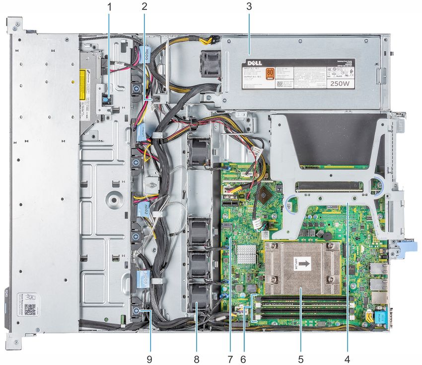
Figure 5. Inside the system - 4 x 3.5-inch drive system
1. Optical drive 2. Intrusion switch
3. Cabled AC power supply unit 4. Expansion card riser
5. Processor and heat sink 6. Memory module sockets
7. System board 8. Fan (4)
9. Drive backplane
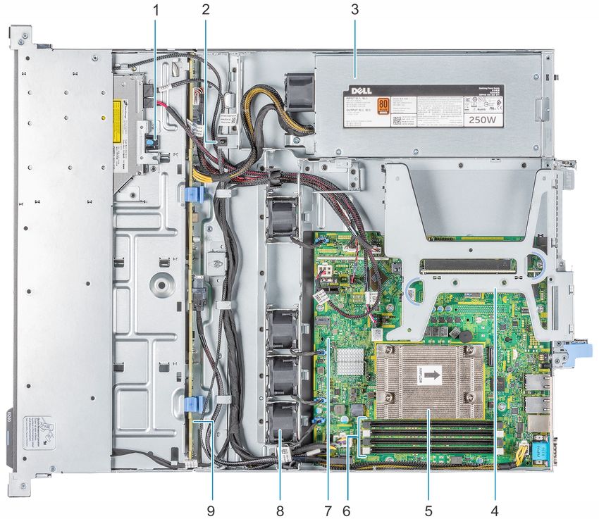
Chassis views and features 13Figure 6. Inside the system - 4 x 3.5-inch cabled drive system 1. Optical drive 2. Intrusion switch 3. Cabled AC power supply unit 4. Expansion card riser 5. Processor and heat sink 6. Memory module sockets 7. System board 8. Fan (4) 9. Cabled drive Locating the information tag of your system Your system is identified by a unique Express Service Code and Service Tag number. You can view the Express Service Code and Service Tag by pulling out the information tag located on the front of the system. Alternatively, the information may be on the Mini Enterprise Service Tag (MEST) label on the chassis, on the rear of the system. This information is used by Dell to route support calls to the appropriate personnel. Figure 7. Locating Service Tag of your system 1. Information tag (front view) 2. Information tag (back view) 14 Chassis views and features
3. OpenManage Mobile (OMM) label                  4. iDRAC MAC address and iDRAC secure password label
5. Service Tag, Express Service Code, QRL label

                                                                         Chassis views and features      15
4
Processor
The PowerEdge R240 is entry-level single-socket rack server based on the Intel® Xeon® E-2100 and E-2200 processor family.
Topics:
• Processor features
• Supported processors
• Chipset
Processor features
The following list highlights the features of the Intel® Xeon E-2100 and E-2200 processor family:
● Up to eight execution cores per processor
● Four DMI3 lanes
● 16 PCIe Gen 3 links capable of 8.0 GT/s
● Socket H4, LGA package (LGA1151)
● Integrated 2 channel DDR4 memory controller
● Execute Disable Bit
● Support Turbo Boost Technology 2.0
● Increases CPU frequency if operating below thermal, power, and current limits
● Intel® Virtualization Technology (Intel® VT)
NOTE: We do not support graphics with E-2100 and E-2200 processors, Graphics cannot be enabled on Dell servers using
this processor due to technical restrictions.
Software Guard Extensions (SGX): Intel SGX functions are available on Coffee Lake Refresh SKUs: Xeon E-2274G, E-2276G,
E-2286G, E-2288G processors and on these original Coffee Lake SKUs: Xeon E-2174G, E-2176G, E-2186G processors on
PowerEdge R240. SGX option will be available in BIOS SETUP only if one of the supported processors are installed.
Supported processors
Table 3. Supported processors
Coffee Lake Refresh Processors
Model Speed Power Cores L3 Cache Threads Turbo Max Hyper- SGX
(GHz) (Watts) (MB) Memory threading Support
Speed
(MT/s)
E-2288G 3.7 95 8 16 16 Yes 2666 Yes Y
E-2286G 4.0 95 6 12 12 Yes 2666 Yes Y
E-2278G 3.4 80 8 12 16 Yes 2666 Yes N
E-2276G 3.8 80 6 12 12 Yes 2666 Yes Y
E-2274G 4.0 83 4 8 8 Yes 2666 Yes Y
E-2246G 3.6 80 6 12 12 Yes 2666 Yes N
E-2244G 3.8 71 4 8 8 Yes 2666 Yes N
E-2236 3.4 80 6 12 12 Yes 2666 Yes N
E-2234 3.6 71 4 8 8 Yes 666 Yes N
16 ProcessorTable 3. Supported processors (continued)
Coffee Lake Refresh Processors
Model Speed Power Cores L3 Cache Threads Turbo Max Hyper- SGX
(GHz) (Watts) (MB) Memory threading Support
Speed
(MT/s)
E-2226G 3.4 80 6 12 6 Yes 2666 Yes N
E-2224 3.4 71 4 8 4 Yes 2666 Yes N
Core i3 3.6 65 4 8 4 No 2666 No N
9100
Pentium 3.8 58 2 4 4 No 2666 No N
G5420
Celeron 3.2 54 2 2 2 No 2666 No N
G4930
Coffee Lake Refresh Processors
Model Speed Power Cores L3 Cache Threads Turbo Max Hyper- SGX
(GHz) (Watts) (MB) Memory threading Support
Speed
(MT/s)
E-2186G 3.8 95 6 12 12 Yes 2666 Yes Y
E-2176G 3.7 80 6 12 12 Yes 2666 Yes Y
E-2174G 3.8 71 4 8 8 Yes 2666 Yes Y
E-2146G 3.5 80 6 12 12 Yes 2666 Yes N
E-2144G 3.6 71 4 8 8 Yes 2666 Yes N
E-2136 3.3 80 6 12 12 Yes 2666 Yes N
E-2134 3.5 71 4 8 8 Yes 2666 Yes N
E-2126G 3.3 80 6 12 6 Yes 2666 No N
E-2124 * 3.3 71 4 8 4 Yes 2666 No N
Core i3 3.6 65 4 6 4 No 2666 No N
8100
Pentium 3.8 54 2 4 2 No 2666 No N
G5500
Celeron 3.1 54 2 2 2 No 2666 No N
G4900
Chipset
The PowerEdge R240 incorporates the Intel® C246 chipset. The following high level features supported by the chipset and may
not implemented on R240:
PCH feature C246 R240
PCH feature C246 R240
TXT Y Y
Node Manager Y N
ECC Y Y
Processor 17PCH feature C246 R240 FlexIO - USB3.0 - 10 (means 6 is enough) 10 3 USB 2.0 4 4 FlexIO - 8 SATA ports 8 5 FlexIO - SATA Express 3 0 FlexIO - PCIE 3.0 ports - additional required 20 8 SPI (MB) FW image 7 UI Intel vPRO/AMT11 Y N Rapid Strorage technology Y N Rapid Strorage technology enterprise Y N Data Center Graphics N N supported displays 3 N Int. Gbe MAC Y N eSPI Y N IO Flex - ability to change SATA/PCIE/USB Y N Software Guard Extensions (SGX) N Y ● Direct Media Interface 3 (DMI3) connects the CPU1 to the PCH ● PCI Express Generation 3 (PCIe Gen3) is capable of 8 GT/s bit rate ● PCH SATA controller provides hardware support for Advanced Host Controller Interface (AHCI), a standardized programming interface for SATA host controllers developed through a joint industry effort. ● Low Pin Count Interface (LPC) ● Serial Peripheral Interface (SPI) ● Advanced Programmable Interrupt Controller (APIC) ● Real-Time Clock ● GPIO Serial Expander (GSX) is the capability provided by the PCH to expand the GPIOs on a platform that needs more GPIOs than the ones provided by the PCH. ● System Management Bus (SMBus) 2.0 ● JTAG Boundary-Scan 18 Processor
5
                                                                                                        Memory
The PowerEdge R240 Integrated Memory Controller (IMC) supports DDR4/-RS protocols with two independent, 64-bit wide
channels.
The maximum system population at launch will be 64GB. (4 DIMM slots x16 GB DDR4 UDIMM)
● System Memory Organization Modes
   ○ The IMC supports two memory organization modes, single-channel and dual-channel. Depending upon how the DDR
      Schema and DIMM Modules are populated in each memory channel, a number of different configurations can exist.
● Single-Channel Mode
   ○ In this mode, all memory cycles are directed to a single channel. Single-Channel mode is used when either the Channel A
      or Channel B DIMM connectors are populated in any order, but not both.
● Dual-Channel Mode – Intel® Flex Memory Technology Mode
   ○ The IMC supports Intel Flex Memory Technology Mode. Memory is divided into a symmetric and asymmetric zone. The
      symmetric zone starts at the lowest address in each channel and is contiguous until the asymmetric zone begins or until
      the top address of the channel with the smaller capacity is reached. In this mode, the system runs with one zone of
      dual-channel mode and one zone of single-channel mode, simultaneously, across the whole memory array.

Memory Features
Key features of the PowerEdge R240 memory system include:
● Unbuffer (UDIMM) ECC DDR4 technology
● Each channel carries 64 data and 8 ECC bits
● Up to 64 GB of UDIMM memory (4 x 16GB UDIMM)
● Up to 2666 MT/s DIMMs
● Single DIMM configuration with 8 GB DIMM at socket DIMM A1
● Flexible Memory Configuration
● ODT (On Die Termination)
● Clock gating (CKE) to conserve power when DIMMs are not accessed
   ○ DIMMs enter a low power self-refresh mode
● I2C access to SPD EEPROM for access to thermal sensors
● Memory Optimized (Independent Channel) Mode
● 100% Single Bit Error Correction
● Memory Off-lining is NOT supported

Memory speed
The system will run all memory on all CPUs and channels at the same speed and voltage. By default the system will run at the
highest speed for the lowest voltage of the worst case channel DIMM configuration.
Operating speed of the memory is determined by:
●   Supported speed of the DIMMs
●   DIMM configuration on any channel
●   Max speed supported by the CPU
●   Speed requested by user in BIOS setup screen
Operating voltage of the system is determined by:
● Voltages supported by the DIMMs which is 1.2V
● Voltage supported by the platform.
The following table shows the memory populations and the system speed frequencies:

                                                                                                              Memory           19
Table 4. Memory populations and system speed
DIMM DIMM Ranking Capacity DIMM Rated 1 DIMM per channel 2 DIMMs per
Type voltage channel
UDIMM 1R/2R 8GB, and 16GB DDR4 (1.2V) 2666 2666
Supported Configurations
The following table highlights the PowerEdge R240 DIMM offering list
DIMM Speed DIMM Type DIMM Ranks per Data Width SDDC DIMM Volts Comments
Capacity DIMM Support
(GB)
2666 UDIMM 8 1 x8 Advanced 1.2
ECC
2666 UDIMM 8 1 x8 Advanced 1.2 BCC Version
ECC
2666 UDIMM 16 1 x8 Advanced 1.2
ECC
2666 UDIMM 16 1 x8 Advanced 1.2 BCC Version
ECC
2400 UDIMM 4 1 x8 Advanced 1.2
ECC
2400 UDIMM 8 1 x8 Advanced 1.2
ECC
2400 UDIMM 8 1 x8 Advanced 1.2 BCC Version
ECC
2400 UDIMM 16 2 x8 Advanced 1.2
ECC
2400 UDIMM 16 2 x8 Advanced 1.2 BCC Version
ECC
2133 UDIMM 4 1 x8 Advanced 1.2
ECC
2133 UDIMM 4 1 x8 Advanced 1.2 BCC Version
ECC
2133 UDIMM 8 2 x8 Advanced 1.2
ECC
2133 UDIMM 8 1 x8 Advanced 1.2 BCC Version
ECC
2133 UDIMM 16 2 x8 Advanced 1.2
ECC
2133 UDIMM 16 2 x8 Advanced 1.2 BCC Version
ECC
20 Memory6
Storage
The PowerEdge R240 supports the following drive configurations:
● 2 x 3.5-inch cabled HDD configuration
● 4 x 3.5-inch cabled HDD configuration
● 4 x 3.5-inch hot-plug HDD configuration
● 4 x 2.5-inch (in 3.5-inch carrier) hot-plug HDD configuration
Topics:
• Supported drives
• Storage controller specifications
• Optical Drives
• Tape Drives
• Internal Dual SD Module
Supported drives
The PowerEdge R240 system supports SAS, SATA, Nearline SAS drives and SSD drives.
NOTE: SSD drives only available in the hot-plug configurations
Table 5. Supported Drives
x2 cabled chassis x4 cabled chassis x4 hot plug hard drive
Hard drive form factor 3.5-inch only 3.5-inch only 3.5-inch or 2.5-inch only
Hard drive type SATA, Nearline SAS SATA, Nearline SAS SATA, Nearline SAS, SAS,
SSD
NOTE: Both 6Gbps and 12Gbps drives are supported by the PowerEdge R240
Storage controller specifications
The PowerEdge R240 system supports:
● Internal storage controller cards: PERC H330, H730P, S140, HBA330 and Boot Optimized Storage Subsystem (BOSS)
modules.
● External storage controller cards: 12 Gbps SAS HBA.
Optical Drives
The PowerEdge R240 supports one of the following internal optical drive options:
● DVD-ROM
● DVD+ROM
Tape Drives
Due to its dense form factor, the PowerEdge R240 does not support internal tape drives. However, here is a list of supported
external tape backup devices:
Storage 21Supported external tape drives: ● External LTO-6 SAS tape drives ● External LTO-7 SAS tape drives ● External LTO-8 SAS tape drives Internal Dual SD Module The Internal Dual SD Module (IDSDM) is optional. The IDSDM contains two SD ports directly on the motherboard. The modules are redundant. Supported iDSDM microSD cards capacity are 8/16/32/64GB The IDSDM card provides the following functions: ● Dual SD interface is maintained in a mirrored configuration (primary and secondary SD) ● Provides full RAID1 functionality ● Dual SD cards are not required; the module can operate with only one card but will provide no redundancy ● Enables support for Secure Digital eXtended Capacity (SDXC) cards ● USB interface to host system ● I²C interface to host system and onboard EEPROM for out-of-band status reporting ● Onboard LEDs show status of each SD card ● A BIOS Setup Redundancy setting supports Mirror Mode or Disabled Boot Optimized Storage Subsystem (BOSS) BOSS is offered as a means of booting the PowerEdge R240 servers to a full OS when: ● A solution such as IDSDM may be desired, but the target OS for BOSS is a full OS (not just a hypervisor) ● The user needs to maximize their number of drive bays BOSS cards take up a PCIe slot and are not hot-plug capable. 1x or 2x 240GB modules are available. Dual (2x) module configs can be set up for either RAID 1 or No RAID. Single (1x) module configs can only be set up in a No RAID config. 22 Storage
7
                                                                  Networking and PCIe
The following lists the supported add in communication cards:
● Intel Ethernet I350 DP 1Gb server adapter – FH or LP
● Intel Ethernet I350 QP 1Gb server adapter – FH or LP
● Broadcom 5720 DP 1Gb Network Interface Card – FH or LP
● Broadcom 5719 QP 1Gb Network Interface Card – FH or LP

PCIe slots
The PowerEdge R240 provides one riser PCIe expansion slot and one R/A PCIe internal storage slot:
● Slot 1 : One x8 PCIe Gen3 for LP from CPU (x4 lanes)
● Slot 2 : One x16 PCIe Gen3 for FH/HL from CPU (x8 lanes)

PCI card dimensions
The PCI card dimensions allowed in the PowerEdge R240 are as below:

Table 6. PCI card dimensions
Card type                   Height                                         Length
Slot 1 (Low Profile, half   68.90 mm (2.731 inches) max                    167.65 mm (6.600 inches) max
length card)
Slot 2 (Full height, Half   111.15 mm (4.376 inches) max                   167.65 mm (6.600 inches) max
length card)

                                                                                             Networking and PCIe   23
8
Power, thermal, and acoustics
Topics:
• Power supply units
• Thermal
• Acoustics
Power supply units
The power supply subsystem is formed with a AC-DC cable power supply. The power supply provides +12V and +12Vaux for
non-redundant design. There are several voltage regulators in the system to supply different voltage levels needed by different
logic devices.
The Dell EMC PowerEdge R240 supports 250W and 450W cabled AC power supply units (PSU).
The following table shows the technical specifications of the power supply:
Table 7. Dell EMC PowerEdge R240 PSU specifications
AC
Heat
dissipation High line Low line
PSU Class (maximum) Frequency Voltage 100–240 V 100–120 V Current
250 W AC Bronze 1039 BTU/hr 100-240 V 250 W N/A 4.0A - 2.0 A
50/60 Hz AC,autorangin
g
450 W AC Platinum 1725 BTU/hr 100-240 V 450 W NA 6.5A - 3.5A
50/60 Hz AC,
autoranging
NOTE: This system is designed to connect to the IT power systems with a phase-to-phase voltage not exceeding 230 V.
Thermal
The thermal design of the PowerEdge R240 reflects the following:
● Optimized thermal design
○ The system layout is architected for an optimum thermal design i.e. system component placement and layout are
designed to provide maximum airflow coverage to critical components with minimum expense of fan power.
○ Custom heat sink designs for CPU, chipset for optimum component cooling
● Comprehensive thermal design
○ The power required to cool a server can contribute a significant amount to the overall system power. Thermal control
is the active management of system cooling through fan speed and system power management to make sure that the
system is reliable while minimizing system fan power consumption, airflow, and system acoustic output.
○ The PowerEdge R240 thermal control system regulates the fan speed based on several different responses from critical
components’ temperature sensors as well as inventory for system configurations:
■ Open and closed loop fan speed control. Open loop control uses system configuration information to determine fan
speed based on system inlet temperature. Closed loop control method uses component temperature feedback from
various sub-systems to dynamically determine optimum fan speeds.
■ Increase airflow through a fan offset if required.
■ Increase airflow through increasing minimum fan speed.
24 Power, thermal, and acousticsAcoustics
PowerEdge R240 acoustics
Dell EMC PowerEdge R240 is a rack-mount server appropriate for attended data center environment. However, lower acoustical
output is attainable with proper hardware or software configurations. For example, the minimum configuration of PowerEdge
R240 is quiet enough for typical office environment. The list below are the PowerEdge R240's acoustical dependencies:
● Ambient Temperature: For a similar workload fan speeds (and thus, acoustical noise) may increase as ambient temperature
increases.
● High Wattage CPU: High-power (TDP) CPU parts may result in higher acoustical noise output.
● Rear Drives: When rear drives are installed in R340, fan speed may increase for cooling the drives, and hence both idle and
operating acoustical outputs may be higher.
● System Thermal Profile Selected in BIOS: The default setting is “Power Optimized (DAPC)”, which generally means
lower fan speed and acoustics. If “Performance Optimized” is selected, fan speed and acoustical noise may increase.
The PowerEdge R240 acoustical performance is characterized for 3 configurations: Minimum, Typical and Feature Rich. The
following tables summarizes the configuration and acoustical performance of the PowerEdge R240. Each configuration has been
tested according to Dell EMC acoustical standards for rack-mounted servers.
Configuration Minimum Typical-1 Typical-2 Feature Rich
CPU Type Intel E-2124 Intel E-2124 Intel E-2124 Intel E-2126G
CPU TDP 71 W 71 W 71 W 80 W
CPU Quantity 1 1 1 1
Memory Type 8GB UDIMM 8GB UDIMM 16GB UDIMM 16GB UDIMM
DIMM Quantity 1 1 2 4
Backplane Type 2x 3.5" Cabled 4x 3.5" Cabled 4X 3.5" Hot-plug 4X 3.5" Hot-plug
Fan Quantity 2 x 4028 3 x 4028 4 x 4028 4 x 4028
HDD Type 3.5" SATA 1-TB 3.5" SATA 1-TB 3.5" SATA 2-TB 3.5" SATA 2-TB
HDD Quantity 1 2 2 4
PSU Type 250 W 250 W 250 W 250 W
PSU Quantity 1 1 1 1
PCI 1 - - PERC H330 PERC H330
PCI 2 - - - -
PCI 3 - - - -
Acoustical Performance: Idle/ Operating @ 25 °C Ambient
LwA-UL² (Bels) Idle 1 4.6 4.6 5.1 5.2
Operating 1 4.7 4.8 5.1 5.2
LpA³ (dBA) Idle 1 39 39 43 43
Operating 1 40 40 43 43
Acoustical Performance: Idle @ 28 °C Ambient
LwA-UL² (Bels) 5.5 5.7 6.1 6.1
LpA³ (dBA) 38 41 45 44
Power, thermal, and acoustics 25Acoustical Performance: Max. Loading @ 35 °C Ambient LwA-UL² (Bels) 7.7 7.7 7.8 7.8 LpA³ (dBA) 59 61 62 62 26 Power, thermal, and acoustics
9
                                           Supported operating systems
The following lists the supported operating systems for the PowerEdge R240:
● Windows 2019 w/Hyper-V Standard
● Windows 2019 Essentials
● Windows 2016 w/Hyper-V Standard
● Windows 2016 Essentials
● Windows 2012 R2 Essentials
● Windows 2012 R2 Standard
        NOTE: Windows 2012 R2 is not supported with E-2200 processor configurations.
●   RHEL 7.5
●   SLES 15
●   Ubuntu server 18.04.1
●   Citrix XenServer 7.1
●   VMWare ESXi 6.7
●   VMWare ESXi 6.5

                                                                                  Supported operating systems   27
10
Dell EMC OpenManage systems management
Figure 8. Dell EMC OpenManage Portfolio
Dell EMC delivers management solutions that help IT Administrators effectively deploy, update, monitor, and manage IT assets.
OpenManage solutions and tools enable you to quickly respond to problems by helping them to manage Dell EMC servers
effectively and efficiently; in physical, virtual, local, and remote environments, operating in-band, and out-of-band (agent-free).
The OpenManage portfolio includes innovative embedded management tools such as the integrated Dell Remote Access
Controller (iDRAC), Chassis Management Controller and Consoles like OpenManage Enterprise, OpenManage Power Manager
plug in, and tools like Repository Manager.
Dell EMC has developed comprehensive systems management solutions based on open standards and has integrated with
management consoles that can perform advanced management of Dell hardware. Dell EMC has connected or integrated the
advanced management capabilities of Dell hardware into offerings from the industry's top systems management vendors and
frameworks such as Ansible, thus making Dell EMC platforms easy to deploy, update, monitor, and manage.
The key tools for managing Dell EMC PowerEdge servers are iDRAC and the one-to-many OpenManage Enterprise console.
OpenManage Enterprise helps the system administrators in complete lifecycle management of multiple generations of
PowerEdge servers. Other tools such as Repository Manager, which enables simple yet comprehensive change management.
OpenManage tools integrate with systems management framework from other vendors such as VMware, Microsoft, Ansible, and
ServiceNow. This enables you to use the skills of the IT staff to efficiently manage Dell EMC PowerEdge servers.
Topics:
• Server and Chassis Managers
• Dell EMC consoles
• Automation Enablers
• Integration with third-party consoles
• Connections for third-party consoles
• Dell EMC Update Utilities
• Dell resources
28 Dell EMC OpenManage systems managementServer and Chassis Managers
● Integrated Dell Remote Access Controller (iDRAC)
● iDRAC Service Module (iSM)
Dell EMC consoles
● Dell EMC OpenManage Enterprise
● Dell EMC Repository Manager (DRM)
● Dell EMC OpenManage Enterprise Power Manager plugin to OpenManage Enterprise
● Dell EMC OpenManage Mobile (OMM)
Automation Enablers
● OpenManage Ansible Modules
● iDRAC RESTful APIs (Redfish)
● Standards-based APIs (Python, PowerShell)
● RACADM Command Line Interface (CLI)
● GitHub Scripting Libraries
Integration with third-party consoles
● Dell EMC OpenManage Integrations with Microsoft System Center
● Dell EMC OpenManage Integration for VMware vCenter (OMIVV)
● Dell EMC OpenManage Ansible Modules
● Dell EMC OpenManage Integration with ServiceNow
Connections for third-party consoles
● Micro Focus and other HPE tools
● OpenManage Connection for IBM Tivoli
● OpenManage Plug-in for Nagios Core and XI
Dell EMC Update Utilities
● Dell System Update (DSU)
● Dell EMC Repository Manager (DRM)
● Dell EMC Update Packages (DUP)
● Dell EMC Server Update Utility (SUU)
● Dell EMC Platform Specific Bootable ISO (PSBI)
Dell resources
For additional information about white papers, videos, blogs, forums, technical material, tools, usage examples, and other
information, go to the OpenManage page at https://www.dell.com/openmanagemanuals or the following product pages:
Dell EMC OpenManage systems management 29Table 8. Dell resources
Resource Location
Integrated Dell Remote Access Controller (iDRAC) https://www.dell.com/idracmanuals
iDRAC Service Module (iSM) https://www.dell.com/support/article/sln310557
OpenManage Ansible Modules https://www.dell.com/support/article/sln310720
OpenManage Essentials (OME) https://www.dell.com/support/article/sln310714
OpenManage Mobile (OMM) https://www.dell.com/support/article/sln310980
OpenManage Integration for VMware vCenter (OMIVV) https://www.dell.com/support/article/sln311238
OpenManage Integration for Microsoft System Center https://www.dell.com/support/article/sln312177
(OMIMSSC)
Dell EMC Repository Manager (DRM) https://www.dell.com/support/article/sln312652
Dell EMC System Update (DSU) https://www.dell.com/support/article/sln310654
Dell EMC Platform Specific Bootable ISO (PSBI) Dell.com/support/article/sln296511
Dell EMC Chassis Management Controller (CMC) www.dell.com/support/article/sln311283
OpenManage Connections for Partner Consoles https://www.dell.com/support/article/sln312320
OpenManage Enterprise Power Manager https://www.dellemc.com/solutions/openmanage/power-
management.htm
OpenManage Integration with ServiceNow (OMISNOW) Dell.com/support/article/sln317784
NOTE: Features may vary by server. Please refer to the product page on https://www.dell.com/manuals for details.
30 Dell EMC OpenManage systems management11
Appendix A. Additional specifications
The following sections contain information about additional system specifications.
Topics:
• Technical specifications
Technical specifications
The technical and environmental specifications of your system are outlined in this section.
Chassis dimensions
Figure 9. Chassis dimensions
Table 9. Dell EMC PowerEdge R240 chassis dimensions
Xa Xb Y Za Zb Zc
482.0 mm 434.0 mm 42.8 mm With bezel: 35.64 534.496 mm 573.596 mm
(18.97 inches) (17.08 inches) (1.68 inches) mm (1.4 inches) (21.04 inches) (22.58 inches)
Appendix A. Additional specifications 31Table 9. Dell EMC PowerEdge R240 chassis dimensions
Xa Xb Y Za Zb Zc
Without bezel: 22.0
mm (0.87 inches)
Chassis weight
Table 10. Dell EMC PowerEdge R240 system weight
System configuration Maximum weight (with all drives/SSDs)
4 x 3.5-inch drives 12.2 kg (26.89 lb)
Video specifications
The Dell EMC PowerEdge R240 system supports integrated Matrox G200 graphics controller with 16 MB of video frame buffer.
Table 11. Supported video resolution options
Resolution Refresh rate (Hz) Color depth (bits)
640 x 480 60, 72 8, 16, 24
800 x 600 60, 75, 85 8, 16, 24
1024 x 768 60, 75, 85 8, 16, 24
1152 x 864 60, 75, 85 8, 16, 24
1280 x 1024 60, 75 8, 16, 24
USB ports specifications
Table 12. Dell EMC PowerEdge R240 system USB specifications
Front Rear Internal
USB port type No. of ports USB port type No. of ports USB port type No. of ports
USB 2.0- One USB 3.0- Two Internal USB 3.0- One
compliant port compliant ports compliant port
Micro USB 2.0- One
compliant port for
iDRAC Direct
NOTE: The micro USB 2.0 compliant port can only be used as an iDRAC Direct or a management port.
Drives
The PowerEdge R240 system supports SAS, SATA drives and Solid State Drives (SSDs).
Drives:
● 4 x 3.5-inch hot-swappable SAS, SATA, or SSD
● 4 x 3.5-inch cabled drives
● 2 x 3.5-inch cabled drives
NOTE: LED functionality is not supported on cabled hard disk drive configuration.
Backplane:
● Supports 4 x 3.5-inch and 4 x 2.5-inch SAS, SATA, or SSD drives passive backplane
32 Appendix A. Additional specifications● Up to 4 x 3.5-inch SAS, SATA, or SSD drives
NIC ports specifications
The Dell EMC PowerEdge R240 system supports up to two 10/100/1000 Mbps Network Interface Controller (NIC) ports that
are located on the back panel.
Environmental specifications
NOTE: For additional information about environmental certifications, refer to the Product Environmental Datasheet located
with the Manuals & Documents on www.dell.com/support/home.
Table 13. Temperature specifications
Temperature Specifications
Storage -40–65°C (-40–149°F)
Continuous operation (for altitude less than 950 10–35°C (50–95°F) with no direct sunlight on the equipment
m or 3117 ft)
Fresh air For information about fresh air, see the Expanded operating temperature
section.
Maximum temperature gradient (operating and 20°C/h (68°F/h)
storage)
Table 14. Relative humidity specifications
Relative humidity Specifications
Storage 5% to 95% RH with 33°C (91°F) maximum dew point.
Atmosphere must be noncondensing at all times.
Operating 10% to 80% RH with 29°C (84.2°F) maximum dew point.
Table 15. Maximum vibration specifications
Maximum vibration Specifications
Operating 0.26 G rms at 5 Hz to 350 Hz (all operation orientations)
Storage 1.88 G rms at 10 Hz to 500 Hz for 15 minutes (all six sides tested)
Table 16. Maximum shock pulse specifications
Maximum shock pulse Specifications
Operating Six consecutively executed shock pulses in the positive and negative x, y,
and z axis of 6 G for up to 11 ms.
Storage Six consecutively executed shock pulses in the positive and negative x, y,
and z axis (one pulse on each side of the system) of 71 G for up to 2 ms.
Table 17. Maximum altitude specifications
Maximum altitude Specifications
Operating 3048 m (10,000 ft)
Storage 12,000 m (39,370 ft)
Appendix A. Additional specifications 33Table 18. Operating temperature derating specifications
Operating temperature derating Specifications
Up to 35°C (95°F) Maximum temperature is reduced by 1°C/300 m (1°F/547 ft), above 950
m (3,117 ft).
35–40°C (95–104°F) Maximum temperature is reduced by 1°C/175 m (1°F/319 ft), above 950 m
(3,117 ft).
40–45°C (104–113°F) Maximum temperature is reduced by 1°C/125 m (1°F/228 ft), above 950 m
(3,117 ft).
Standard operating temperature
Table 19. Standard operating temperature specifications
Standard operating temperature Specifications
Continuous operation (for altitude less than 950 m or 10–35°C (50–95°F) with no direct sunlight on the equipment.
3117 ft)
Expanded operating temperature
Table 20. Expanded operating temperature specifications
Expanded operating temperature Specifications
Continuous operation 5°C–40°C at 5% to 85% RH with 29°C dew point.
NOTE: Outside the standard operating temperature
(10°C–35°C), the system can operate continuously in
temperatures as low as 5°C and as high as 40°C.
For temperatures 35°C– 40°C, derate maximum allowable
temperature by 1°C per 175 m (1°F per 319 ft) above 950
m (3,1171 ft).
≤ 1% of annual operating hours -5°C–45°C at 5% to 90% RH with 29°C dew point.
NOTE: Outside the standard operating temperature
(10°C–35°C), the system can operate down to -5°C or
up to 45°C for a maximum of 1% of its annual operating
hours.
For temperatures 40°C– 45°C, derate maximum allowable
temperature by 1°C per 125 m (1°F per 228 ft) above 950
m (3.117 ft).
NOTE: When operating in the expanded temperature range, the performance of the system may be impacted.
NOTE: When operating in the expanded temperature range, ambient temperature warnings may be reported on the System
Event Log.
Expanded operating temperature restrictions
● Do not perform a cold startup of the system below 5°C.
● The operating temperature specified is for a maximum altitude of 950m for fresh air cooling.
● Four system fans are required.
● Support for up to 71W processor.
● GPU is not supported.
● Non-Dell qualified peripheral cards and/or peripheral cards greater than 25 W are not supported.
34 Appendix A. Additional specificationsParticulate and gaseous contamination specifications
The following table defines the limitations that help avoid any damages to the IT equipment and/or, or both failure from
particulate and gaseous contamination. If the levels of particulate or gaseous pollution exceed the specified limitations and
results in equipment damage or failure, you must rectify the environmental conditions. Remediation of environmental conditions
is the responsibility of the customer.
Table 21. Particulate contamination specifications
Particulate contamination Specifications
Air filtration Data center air filtration as defined by ISO Class 8 per ISO
14644-1 with a 95% upper confidence limit.
NOTE: This condition applies to data center environments
only. Air filtration requirements do not apply to IT
equipment designed to be used outside a data center, in
environments such as an office or factory floor.
NOTE: Air entering the data center must have MERV11 or
MERV13 filtration.
Conductive dust Air must be free of conductive dust, zinc whiskers, or other
conductive particles.
NOTE: This condition applies to data center and non-data
center environments.
Corrosive dust ● Air must be free of corrosive dust.
● Residual dust present in the air must have a deliquescent
point less than 60% relative humidity.
NOTE: This condition applies to data center and non-data
center environments.
Table 22. Gaseous contamination specifications
Gaseous contamination Specifications
Copper Coupon Corrosion12
Appendix B. Standards compliance
Table 23. Industry standard documents
Standard URL for information and specifications
ACPI Advance Configuration and Power Interface acpi.info
Specification, v2.0c
Ethernet IEEE 802.3-2005 standards.ieee.org/getieee802/802.3.html
HDG Hardware Design Guide Version 3.0 for Microsoft microsoft.com/whdc/system/platform/pcdesign/desguide/
Windows Server serverdg.mspx
IPMI Intelligent Platform Management Interface, v2.0 intel.com/design/servers/ipmi
DDR4 Memory DDR4 SDRAM Specification jedec.org/standards-documents/docs/jesd79-4.pdf
PCI Express PCI Express Base Specification Rev. 2.0 and 3.0 pcisig.com/specifications/pciexpress
PMBus Power System Management Protocol Specification, pmbus.info/specs.html
v1.2
SAS Serial Attached SCSI, v1.1 t10.org
SATA Serial ATA Rev. 2.6; SATA II, SATA 1.0a Extensions, sata-io.org
Rev. 1.2
SMBIOS System Management BIOS Reference Specification, dmtf.org/standards/smbios
v2.7
TPM Trusted Platform Module Specification, v1.2 and v2.0 trustedcomputinggroup.org
UEFI Unified Extensible Firmware Interface Specification, v2.1 uefi.org/specifications
USB Universal Serial Bus Specification, Rev. 2.0 usb.org/developers/docs
36 Appendix B. Standards compliance13
Appendix C Additional resources
Table 24. Additional resources
Resource Description of contents Location
Installation and Service Manual This manual, available in PDF format, provides the following Dell.com/Support/Manuals
information:
● Chassis features
● System Setup program
● System messages
● System codes and indicators
● System BIOS
● Remove and replace procedures
● Troubleshooting
● Diagnostics
● Jumpers and connectors
Getting Started Guide This guide ships with the system, and is also available in PDF Dell.com/Support/Manuals
format. This guide provides the following information:
● Initial setup steps
● Key system features
● Technical specifications
Rack Installation Instructions This document ships with the rack kits, and provides Dell.com/Support/Manuals
instructions for installing a server in a rack.
Information Update This document ships with the system, is also available in PDF Dell.com/Support/Manuals
format online, and provides information on system updates.
System Information Label The system information label documents the system board Inside the system chassis
layout and system jumper settings. Text is minimized due cover
to space limitations and translation considerations. The label
size is standardized across platforms.
Quick Resource Locator (QRL) This code on the chassis can be scanned by a phone Inside the system chassis
application to access additional information and resources for cover
the server, including videos, reference materials, service tag
information, and Dell EMC contact information.
Energy Smart Solution Advisor The Dell EMC online ESSA enables easier and more Dell.com/calc
(ESSA) meaningful estimates to help you determine the most
efficient configuration possible. Use ESSA to calculate the
power consumption of your hardware, power infrastructure,
and storage.
Appendix C Additional resources 3714
Appendix D. Support and deployment
services
Topics:
• Dell EMC ProDeploy Enterprise Suite
• Deployment services
• Dell EMC Remote Consulting Services
• Dell EMC Data Migration Service
• ProSupport Enterprise Suite
• ProSupport Plus
• ProSupport
• ProSupport One for Data Center
• Support Technologies
• Additional professional services
• Dell Education Services
• Dell EMC Global Infrastructure Consulting Services
• Dell EMC Managed Services
Dell EMC ProDeploy Enterprise Suite
ProDeploy Enterprise Suite gets your server out of the box and into optimized production—fast. Our elite deployment engineers
with broad and deep experience utilizing best-in-class processes along with our established global scale can help you around the
clock and around the globe. From simple to the most complex server installations and software integration, we take the guess
work and risk out of deploying your new server technology.
Figure 10. ProDeploy Enterprise Suite capabilities
NOTE: Hardware installation not applicable on selected software products.
38 Appendix D. Support and deployment servicesDell EMC ProDeploy Plus
From beginning to end, ProDeploy Plus provides the skill and scale needed to successfully execute demanding deployments
in today's complex IT environments. Certified Dell EMC experts start with extensive environmental assessments and detailed
migration planning and recommendations. Software installation includes set up of most versions of Dell EMC SupportAssist and
OpenManage system management utilities. Post-deployment configuration assistance, testing, and product orientation services
are also available.
Dell EMC ProDeploy
ProDeploy provides full service installation and configuration of both server hardware and system software by certified
deployment engineers including set up of leading operating systems and hypervisors as well as most versions of Dell EMC
SupportAssist and OpenManage system management utilities. To prepare for the deployment, we conduct a site readiness
review and implementation planning exercise. System testing, validation, and full project documentation with knowledge transfer
complete the process.
Dell EMC Basic Deployment
Basic Deployment delivers worry-free professional installation by experienced technicians who know Dell EMC servers inside and
out.
Dell EMC Residency Services
Residency Services helps customers transition to new capabilities quickly with the assistance of on-site or remote Dell EMC
experts whose priorities and time you control. Residency experts can provide post implementation management and knowledge
transfer related to a new technology acquisition or day-to-day operational management of the IT infrastructure.
Deployment services
Deployment services details and exceptions can be found in service description documents at the Enterprise Configuration and
Deployment pageon Dell.com.
Dell EMC Remote Consulting Services
When you are in the final stages of your PowerEdge server implementation, you can rely on Dell EMC Remote Consulting
Services and our certified technical experts to help you optimize your configuration with best practices for your software,
virtualization, server, storage, networking, and systems management.
Dell EMC Data Migration Service
Protect your business and data with our single point of contact to manage your data migration project. Your project manager will
work with our experienced team of experts to create a plan using industry-leading tools and proven processes based on global
best practices to migrate your existing files and data so your business system get up and running quickly and smoothly.
ProSupport Enterprise Suite
With the ProSupport Enterprise Suite, we can help you keep your operation running smoothly, so you can focus on running
your business. We will help you maintain peak performance and availability of your most essential workloads. ProSupport
Enterprise Suite is a suite of support services that enable you to build the solution that is right for your organization. Choose
support models based on how you use technology and where you want to allocate resources. From the desktop to the data
center, address everyday IT challenges, such as unplanned downtime, mission-critical needs, data and asset protection, support
Appendix D. Support and deployment services 39You can also read