Digital temperature transmitter, model T15 Digitaler Temperaturtransmitter, Typ T15 - Head mounting version, model T15.H Rail mounting version ...
←
→
Page content transcription
If your browser does not render page correctly, please read the page content below
Operating instructions
                                            Betriebsanleitung

Digital temperature transmitter, model T15                                 EN

Digitaler Temperaturtransmitter, Typ T15                                   DE

 Head mounting version, model T15.H   Rail mounting version, model T15.R
EN Operating instructions model T15                                             Page            3 - 36

DE Betriebsanleitung Typ T15                                                    Seite         37 - 65

    Further languages can be found at www.wika.com.

   © 12/2015 WIKA Alexander Wiegand SE & Co. KG
   All rights reserved. / Alle Rechte vorbehalten.
   WIKA® is a registered trademark in various countries.
   WIKA® ist eine geschützte Marke in verschiedenen Ländern.

   Prior to starting any work, read the operating instructions!
   Keep for later use!
                                                                                                          14139245.06 01/2020 EN/DE

   Vor Beginn aller Arbeiten Betriebsanleitung lesen!
   Zum späteren Gebrauch aufbewahren!

    2                                                             WIKA operating instructions model T15
Contents

                            Contents
                                                                                                                                                                  EN

                            1. General information                                                                                                           5
                            2. Design and function                                                                                                           6
                               2.1    Description  .   .   .   .   .   .   .   .   .   .   .   .   .   .   .   .   .   .   .   .   .   .   .   .   .   .   . 6
                               2.2    Dimensions in mm  .   .   .   .   .   .   .   .   .   .   .   .   .   .   .   .   .   .   .   .   .   .   .   .   . 6
                               2.3    Scope of delivery  .  .  .  .  .  .  .  .  .  .  .  .  .  .  .  .  .  .  .  .  .  .  .  .  . 7
                            3. Safety                                                                                                                        8
                               3.1    Explanation of symbols  .  .  .  .  .  .  .  .  .  .  .  .  .  .  .  .  .  .  .  .  .  .  . 8
                               3.2    Intended use  .   .   .   .   .   .   .   .   .   .   .   .   .   .   .   .   .   .   .   .   .   .   .   .   .   .   . 8
                               3.3    Responsibility of the operator  .  .  .  .  .  .  .  .  .  .  .  .  .  .  .  .  .  .  .  .  . 9
                               3.4    Personnel qualification  .   .   .   .   .   .   .   .   .   .   .   .   .   .   .   .   .   .   .   .   .   .   . 9
                               3.5    Labelling, safety marks  .  .  .  .  .  .  .  .  .  .  .  .  .  .  .  .  .  .  .  .  .  . 10
                               3.6    Ex marking  .   .   .   .   .   .   .   .   .   .   .   .   .   .   .   .   .   .   .   .   .   .   .   .   .   .   . 11
                            4. Transport, packaging and storage                                                                                              12
                               4.1    Transport  .   .   .   .   .   .   .   .   .   .   .   .   .   .   .   .   .   .   .   .   .   .   .   .   .   .   .  12
                               4.2    Packaging and storage  .  .  .  .  .  .  .  .  .  .  .  .  .  .  .  .  .  .  .  .  .  . 12
                            5. Commissioning, operation                                                                                                      13
                               5.1 Grounding  .  .  .  .  .  .  .  .  .  .  .  .  .  .  .  .  .  .  .  .  .  .  .  .  .  .  .                                13
                               5.2 Mounting  .   .   .   .   .   .   .   .   .   .   .   .   .   .   .   .   .   .   .   .   .   .   .   .   .   .   .       15
                                 5.2.1 Transmitter in head mounting version (model T15.H)  .  .  .  .  .  .  .  .  .  .  .                                   15
                                 5.2.2 Transmitter in rail mounting version (model T15.R)  .   .   .   .   .   .   .   .   .   .   .   .                     16
                               5.3 Electrical connection  .   .   .   .   .   .   .   .   .   .   .   .   .   .   .   .   .   .   .   .   .   .   .          16
                                 5.3.1 Power supply, 4 ... 20 mA current loop  .  .  .  .  .  .  .  .  .  .  .  .  .  .  .  .                                17
                                 5.3.2 Sensors   .   .   .   .   .   .   .   .   .   .   .   .   .   .   .   .   .   .   .   .   .   .   .   .   .   .   .   18
                               5.4 Configuration  .  .  .  .  .  .  .  .  .  .  .  .  .  .  .  .  .  .  .  .  .  .  .  .  .  .                               19
                                 5.4.1 Configurable monitoring functionality  .  .  .  .  .  .  .  .  .  .  .  .  .  .  .  .  .                              19
                                 5.4.2 Configuration via the PC  .   .   .   .   .   .   .   .   .   .   .   .   .   .   .   .   .   .   .   .   .           19
                                 5.4.3 Programming unit model PU-548  .   .   .   .   .   .   .   .   .   .   .   .   .   .   .   .   .   .                  20
                                 5.4.4 Configuration software WIKAsoft-TT  .   .   .   .   .   .   .   .   .   .   .   .   .   .   .   .   .                 20
                            6. Special conditions for safe use (X conditions)                                                                                21
                               6.1 Approval ATEX und IECEx  .  .  .  .  .  .  .  .  .  .  .  .  .  .  .  .  .  .  .  .  .                                    21
                                 6.1.1 Models T15.x-AC, T15.x-AI  .   .   .   .   .   .   .   .   .   .   .   .   .   .   .   .   .   .   .   .              21
                                 6.1.2 Model T15.x-AN  .  .  .  .  .  .  .  .  .  .  .  .  .  .  .  .  .  .  .  .  .  .  .  .                                21
14139245.06 01/2020 EN/DE

                                 6.1.3 Model T15.x-AE  .  .  .  .  .  .  .  .  .  .  .  .  .  .  .  .  .  .  .  .  .  .  .  .                                21
                               6.2 Approval FM  .   .   .   .   .   .   .   .   .   .   .   .   .   .   .   .   .   .   .   .   .   .   .   .   .   .        22
                                 6.2.1 Models T15.x-AC, T15.x-AI  .   .   .   .   .   .   .   .   .   .   .   .   .   .   .   .   .   .   .   .              22
                                 6.2.2 Model T15.x-AN  .  .  .  .  .  .  .  .  .  .  .  .  .  .  .  .  .  .  .  .  .  .  .  .                                22
                                 6.2.3 Model T15.x-AE  .  .  .  .  .  .  .  .  .  .  .  .  .  .  .  .  .  .  .  .  .  .  .  .                                22

                             WIKA operating instructions model T15                                                                                            3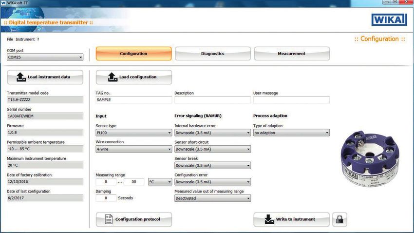
Contents
7. Configuration software WIKAsoft-TT 23
7.1 Starting the software . . . . . . . . . . . . . . . . . . . . . . . 23
7.2 Configuration procedure . . . . . . . . . . . . . . . . . . . . . . 24
7.3 Fault diagnosis . . . . . . . . . . . . . . . . . . . . . . . . . 24
EN 7.4 Measured values . . . . . . . . . . . . . . . . . . . . . . . . . 24
7.5 Configure several instruments identically . . . . . . . . . . . . . . . . 24
8. Faults 25
9. Maintenance 27
10. Return and disposal 27
10.1 Return . . . . . . . . . . . . . . . . . . . . . . . . . . . . 27
10.2 Disposal . . . . . . . . . . . . . . . . . . . . . . . . . . . 27
11. Specifications 28
11.1 Safety-related characteristic values for models T15.x-AI, T15.x-AC . . . . . . . . 29
11.2 Safety-related characteristic values for models T15.x-AN, T15.x-AE . . . . . . . 30
11.3 Versioning per NAMUR NE53 . . . . . . . . . . . . . . . . . . . . 31
12. Accessories 31
Appendix 1: Control drawing CSA/FM 32
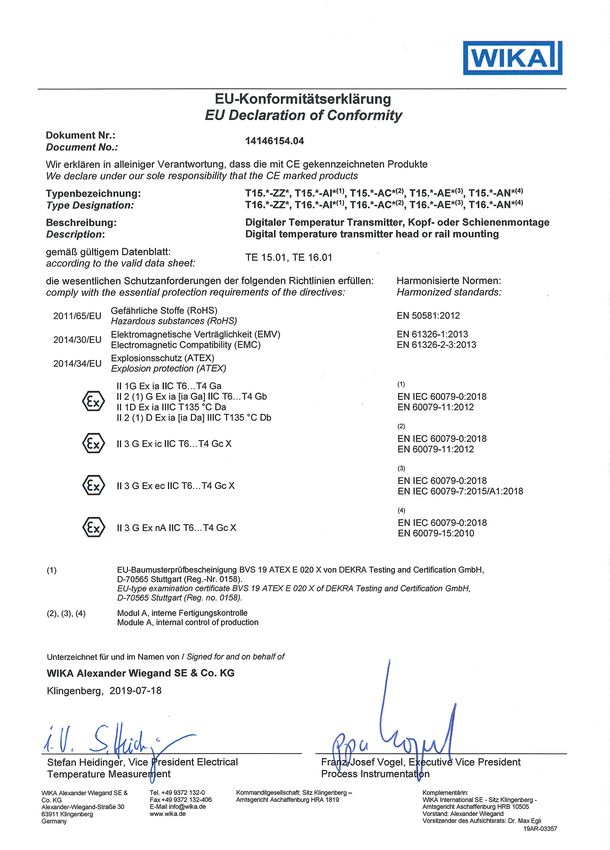
Appendix 2: EU declaration of conformity 36
Declarations of conformity can be found online at www.wika.com.
14139245.06 01/2020 EN/DE
4 WIKA operating instructions model T15
1. General information

                            1. General information
                            ■ The temperature transmitter described in the operating instructions has been designed
                              and manufactured using state-of-the-art technology. All components are subject
                              to stringent quality and environmental criteria during production. Our management
                              systems are certified to ISO 9001 and ISO 14001.
                                                                                                                             EN

                            ■ These operating instructions contain important information on handling the instrument.
                              Working safely requires that all safety instructions and work instructions are observed.

                            ■ Observe the relevant local accident prevention regulations and general safety
                              regulations for the instrument's range of use.

                            ■ The operating instructions are part of the product and must be kept in the immediate
                              vicinity of the instrument and readily accessible to skilled personnel at any time. Pass
                              the operating instructions onto the next operator or owner of the instrument.

                            ■ Skilled personnel must have carefully read and understood the operating instructions
                              prior to beginning any work.

                            ■ The general terms and conditions contained in the sales documentation shall apply.

                            ■ Subject to technical modifications.

                            ■ Further information:
                               - Internet address:           www.wika.de / www.wika.com
                               - Relevant data sheet:        TE 15.01
                               - Application consultant:     Tel.: +49 9372 132-0
                                                             Fax: +49 9372 132-406
                                                             info@wika.de
14139245.06 01/2020 EN/DE

                             WIKA operating instructions model T15                                                       5
2. Design and function

     2. Design and function
     2.1 Description
     The model T15 temperature transmitter is used for converting a resistance value or a
     resistance ratio (potentiometer) into a proportional current signal (4 ... 20 mA). Thus the
EN   sensors are permanently monitored for their fault-free operation.

     The transmitter meets the requirements for:
     ■ Explosion protection (depending on the version)
     ■ Electromagnetic compatibility in accordance with NAMUR recommendation NE21
     ■ Signalling at the analogue output in accordance with NAMUR recommendation NE43
     ■ Sensor break signalling in accordance with NAMUR recommendation NE89 (corrosion
       monitoring sensor connection)

     2.2 Dimensions in mm
     ■ Head mounting version, model T15.H

                                                                         14263238.01

                                                                                                      14139245.06 01/2020 EN/DE

      6                                                       WIKA operating instructions model T15
2. Design and function

                            ■ Rail mounting version, model T15.R

                                                                                14263238.01
                                                                                              EN

                            2.3 Scope of delivery
                            Cross-check scope of delivery with delivery note.
14139245.06 01/2020 EN/DE

                             WIKA operating instructions model T15                   7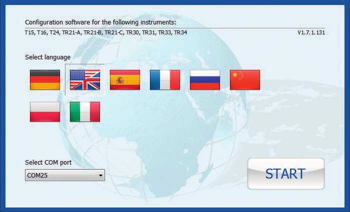
3. Safety

     3. Safety
     3.1 Explanation of symbols

                  WARNING!
EN                ... indicates a potentially dangerous situation that can result in serious injury
                  or death, if not avoided.

                  CAUTION!
                  ... indicates a potentially dangerous situation that can result in light injuries or
                  damage to equipment or the environment, if not avoided.

                  DANGER!
                  ... identifies hazards caused by electrical power. Should the safety
                  instructions not be observed, there is a risk of serious or fatal injury.

                  DANGER!
                  ... indicates a potentially dangerous situation in the hazardous area that can
                  result in serious injury or death, if not avoided.

                  WARNING!
                  ... indicates a potentially dangerous situation that can result in burns, caused
                  by hot surfaces or liquids, if not avoided.

                  Information
                  ... points out useful tips, recommendations and information for efficient and
                  trouble-free operation.

     3.2 Intended use
     The model T15 temperature transmitter is a universal transmitter, configurable via a PC, for
     use with resistance thermometers and potentiometers.

     The instrument has been designed and built solely for the intended use described here,
     and may only be used accordingly.

     The technical specifications contained in these operating instructions must be observed.
                                                                                                         14139245.06 01/2020 EN/DE

     Improper handling or operation of the instrument outside of its technical specifications
     requires the instrument to be taken out of service immediately and inspected by an
     authorised WIKA service engineer.

     The manufacturer shall not be liable for claims of any type based on operation contrary to
     the intended use.

      8                                                       WIKA operating instructions model T15
3. Safety

                            3.3 Responsibility of the operator
                            The instrument is used in the industrial sector. The operator is therefore responsible for
                            legal obligations regarding safety at work.

                            The safety instructions within these operating instructions, as well as the safety, accident
                            prevention and environmental protection regulations for the application area must be               EN
                            maintained.

                            The operator is obliged to maintain the product label in a legible condition.

                            The responsibility for classification of zones lies with the plant operator and not the
                            manufacturer/supplier of the equipment.

                            3.4 Personnel qualification

                                          WARNING!
                                          Risk of injury should qualification be insufficient
                                          Improper handling can result in considerable injury and damage to
                                          equipment.
                                          ▶ The activities described in these operating instructions may only be
                                            carried out by skilled electrical personnel who have the qualifications
                                            described below.

                            Skilled electrical personnel
                            Skilled electrical personnel are understood to be personnel who, based on their technical
                            training, know-how and experience as well as their knowledge of country-specific
                            regulations, current standards and directives, are capable of carrying out work on
                            electrical systems and independently recognising and avoiding potential hazards. The
                            skilled electrical personnel have been specifically trained for the work environment they
                            are working in and know the relevant standards and regulations. The skilled electrical
                            personnel must comply with current legal accident prevention regulations.

                            Special knowledge for working with instruments for hazardous areas:
                            The skilled electrical personnel must have knowledge of ignition protection types,
                            regulations and provisions for equipment in hazardous areas.

                            Special operating conditions require further appropriate knowledge, e.g. of aggressive
                            media.
14139245.06 01/2020 EN/DE

                             WIKA operating instructions model T15                                                         9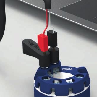
3. Safety
3.5 Labelling, safety marks
■ Head mounting version, model T15.H
T15.H-AIZZZ S# 1106FIDB159
0158
EN V 1.0.0 2015-12 DC 8 ... 30 V
T15.H-AIZZZ S# 1106FIDB159
0158
TAG-NR. Pt100/3 -150 ... +180 °C
WIKA A. Wiegand SE & Co. KG D-63911
BVSTAG-NR.
V 1.0.0Klingenberg
15 ATEX E 139 X
2015-12
Pt100/3 -150 ... +180 °C
Made
DC 8 in
... Germany
30 V
IECEx BVS 15.0112X
WIKA A. Wiegand SE & Co. KG D-63911 Klingenberg Made in Germany
II 1 G Ex ia IIC T6...T4 Ga
II 1 D Ex ia IIIC 15
T135 °C Da T15.H-AIZZZ S# 1106FIDB159
BVS ATEX E 139 X
Tamb T4/T5/T6: -40 ... +85/70/55 °C V 1.0.0 2015-12 DC 8 ... 30 V
IECEx BVS 15.0112X
II 1 G Ex ia IIC T6...T4 Ga TAG-NR. Pt100/3 -150 ... +180 °C
II 1 D Ex ia IIIC T135 °C Da WIKA A. Wiegand SE & Co. KG D-63911 Klingenberg Made in G
Tamb T4/T5/T6: -40 ... +85/70/55 °C
BVS 15 ATEX E 139 X
IECEx BVS 15.0112X
II 1 G Ex ia IIC T6...T4 Ga
II 1 D Ex ia IIIC T135 °C Da
Tamb T4/T5/T6: -40 ... +85/70/55 °C
T15.R-AIZZZ S# 1106FIDB159
■ Rail mounting version, model T15.R
mA-Loop
V 1.0.0 DC 8 ... 30 V
Sensor
Pt100/3 -150 ... +180 °C
TAG-NR.
T15.R-AIZZZ S# 1106FIDB159
mA-Loop
V 1.0.0 DC 8 ... 30 V
Sensor
T15.R-AIZZZ
Pt100/3 -150 ... +180 °C T15.R-AIZZZ S# 1106FIDB159
mA-Loop
V 1.0.0 DC 8 ... 30 V
Sensor
V 1.0.0 2015-12
DC 8 ... 30 V
TAG-NR.
S# 1106FIDB159 Pt100/3 -150 ... +180 °C
0158
Pt100/3 TAG-NR.
-150 ... +180 °C T15.R-AIZZZ
TAG-NR.
V 1.0.0 2015-12 T15.R-AIZZZ
BVS 15DC ATEX
8 ... 30 E
V 139 X S# 1106FIDB159 V 1.0.0 2015-12
IECEx BVS 15.0112X S# 1106FIDB159
0158
Pt100/3 DC 8 ... 30 V
0158
II 2(1)G
-150Ex ia [ia°CGa] IIC T6...T4 Ga
... +180
Pt100/3
II 2(1)D Ex ia [ia Da] IIIC T135 °C Da -150 ... +180 °C
TAG-NR.
Tamb T4/T5/T6: -40 ... +85/70/55 °C TAG-NR.
BVS 15 ATEX E 139 X BVS 15 ATEX E 139 X
IECEx BVS 15.0112X Model IECEx BVS 15.0112X
Resistance sensor
II 2(1)G Ex ia [ia Ga] IIC T6...T4 Ga Firmware
II 2(1)G Ex ia [ia Ga] IIC T6...T4 Ga
II 2(1)D Ex ia [ia Da] IIIC T135 °C Da II 2(1)D Ex ia [ia Da] IIIC T135 °C Da
1
Date
Tambof manufacture
T4/T5/T6: -40(year-month)
... +85/70/55 °C
Tamb T4/T5/T6: -40 ... +85/70/55 °C
2 2 2
Serial number
3 3 3 Sensor information (model, connection
method, power supply,
Resistance measuring range)
sensor
4 4
Resistance sensor
Approval-related
1
data
WIKA A. Wiegand SE & Co. KG D-63911 Klingenberg
1 TAG no.
14139245.06 01/2020 EN/DE
Made in Germany 2 2 2
2 2 2
Pin assignment
3 3 3
3 3 3 4 4
Before4 mounting
4 and commissioning the instrument,
WIKA A. Wiegand ensure
SE & Co. KG D-63911 you
Klingenberg
read the operating instructions! Made in Germany
WIKA A. Wiegand SE & Co. KG D-63911 Klingenberg
Made in Germany
10 WIKA operating instructions model T153. Safety
3.6 Ex marking
DANGER!
Danger to life due to loss of explosion protection
Non-observance of these instructions and their contents may result in the
loss of explosion protection. EN
▶ Observe the safety instructions and further explosion instructions in these
operating instructions.
▶ Follow the requirements of the ATEX directive.
▶ Observe the information given in the applicable type examination
certificate and the relevant country-specific regulations for installation and
use in hazardous areas (e.g. IEC 60079-14, NEC, CEC).
Check whether the classification is suitable for the application. Observe the relevant
national regulations.
Model overview of European approvals
Model Ex marking Ignition protection type
BVS 19 ATEX E 020 X
IECEx BVS 19.0022X
T15.H-AI II 1G Ex ia IIC T6 ... T4 Ga Intrinsically safe equipment
(Head mounting version) II 1D Ex ia IIIC T135 °C Da
T15.R-AI II 2(1)G Ex ia [ia Ga] IIC T6 ... T4 Gb Intrinsically safe equipment
(Rail mounting version) II 2(1)D Ex ia [ia Da] IIIC T135 °C Db
T15.x-AC II 3G Ex ic IIC T6 ... T4 Gc X Intrinsically safe equipment
T15.x-AN II 3G Ex nA IIC T6 ... T4 Gc X Non-incendive equipment
T15.x-AE II 3G Ex ec IIC T6 ... T4 Gc Non-incendive equipment
14139245.06 01/2020 EN/DE
WIKA operating instructions model T15 114. Transport, packaging and storage
4. Transport, packaging and storage
4.1 Transport
Check the instrument for any damage that may have been caused by transport.
Obvious damage must be reported immediately.
EN
CAUTION!
Damage through improper transport
With improper transport, damage to property can occur.
▶ Do not use transmitters with any damage to the exterior!
If the instrument is transported from a cold into a warm environment, the formation of
condensation may result in instrument malfunction. Before putting it back into operation,
wait for the instrument temperature and the room temperature to equalise.
4.2 Packaging and storage
Do not remove packaging until just before mounting.
Permissible conditions at the place of storage:
■ Storage temperature: -40 ... +85 °C
■ Humidity: 95 % r. h. (condensation permitted)
Avoid exposure to the following factors:
■ Direct sunlight or proximity to hot objects
■ Mechanical vibration, mechanical shock (putting it down hard)
■ Soot, vapour, dust and corrosive gases
14139245.06 01/2020 EN/DE
12 WIKA operating instructions model T155. Commissioning, operation
5. Commissioning, operation
Personnel: Skilled electrical personnel
Tools: Screwdriver (see chapter 5.3 “Electrical connection”)
EN
DANGER!
Danger to life from explosion!
Through working in flammable atmospheres, there is a risk of explosion
which can cause death.
▶ Only carry out set-up work in non-hazardous environments!
▶ In hazardous areas, only use temperature transmitters that are approved
for those hazardous areas. Observe the approvals on the product label.
5.1 Grounding
WARNING!
Prevention of electrostatic discharge
When working during a running process operation, measures to prevent
electrostatic discharge from the connection terminals should be taken, as a
discharge could lead to temporary corruption of the measured value.
▶ Only use model T15.H temperature transmitters in grounded thermometer
heads!
▶ Connection of a resistance sensor (e.g. Pt100) to the T15.R with a
shielded cable. The shield must be electrically connected to the case of
the grounded thermometer.
Connection head BSZ
Loop cable
grounded
14139245.06 01/2020 EN/DE
Only use the model T15
temperature transmitter in
grounded thermometers!
WIKA operating instructions model T15 135. Commissioning, operation
Connection head BSZ
grounded shield Field case/
Control cabinet
Sensor wire
EN
Equipotential bonding
grounded grounded T15
Thermowell
with sensor
In applications with higher EMC requirements, using a shielded cable between the
transmitter and the sensor is recommended, especially in connection with long leads to the
sensor. For an exemplary illustration, see drawing.
When using the T15.R rail mounting version and supply wires longer than 30 m, using a
shielded wire is mandatory.
Field case/
Control cabinet
Sensor wire
Equipotential bonding
grounded T15
14139245.06 01/2020 EN/DE
Sensor
grounded shield
14 WIKA operating instructions model T155. Commissioning, operation
5.2 Mounting
5.2.1 Transmitter in head mounting version (model T15.H)
When fitting the head-mounted version of the transmitter, do not exceed a
torque of 1 Nm! EN
The transmitters for head mounting are designed to be mounted on a measuring insert
within a form B, DIN connection head. The connection wires of the measuring insert must
be approx. 50 mm long and insulated.
Mounting example
14139114.01
Mounting in connection head
Insert the measuring insert with the mounted transmitter into the protective fitting and
secure into the connection head using screws in pressure springs.
14139114.01
Mounting in the connection head cover
When mounting it in the cover of a connection head, use suitable screws and matching
washers.
14139245.06 01/2020 EN/DE
Mounting with DIN rail adapter
With the mechanical adapter, available as an accessory, the T15.H head-mounted
transmitters can also be fixed on a DIN rail (see chapter 12 “Accessories”).
WIKA operating instructions model T15 155. Commissioning, operation
5.2.2 Transmitter in rail mounting version (model T15.R)
Fasten the rail mounting case onto a 35 mm DIN rail (EN 60175) by simply locking it into
place without the need for any tools.
Disassembly involves unlocking the detent element.
EN
5.3 Electrical connection
DANGER!
Danger to life caused by electric current
Upon contact with live parts, there is a direct danger to life.
▶ The instrument may only be installed and mounted by skilled personnel.
▶ Operation using a defective power supply unit (e.g. short-circuit from the
mains voltage to the output voltage) can result in life-threatening voltages
at the instrument!
▶ Carry out mounting work only with power disconnected.
▶ The connected wires must be checked to ensure they are connected
properly. Only well-secured wires can guarantee a fault-free operation.
This is protection class 3 equipment for connection at low voltages, which are separated
from the power supply or voltages of greater than AC 50 V or DC 120 V. Preferably, a
connection to an SELV or PELV circuit is recommended; alternatively protective measures
from HD 60346-4-41 (DIN VDE 0100-410).
Alternatively for North America
The connection can be made in line with “Class 2 Circuits” or “Class 2 Power Units” in
accordance with CEC (Canadian Electrical Code) or NEC (National Electrical Code).
The functional galvanic isolation present in the instrument does not ensure sufficient
protection against electrical impulses in the sense of EN 61140.
Recommended tool for screw terminals
Model Screwdriver Tightening torque
T15.H Cross head ('Pozidriv' tip), size 2 (ISO 8764) 0.5 Nm
T15.R Slotted, 3 x 0.5 mm (ISO 2380) 0.5 Nm
14139245.06 01/2020 EN/DE
16 WIKA operating instructions model T155. Commissioning, operation
5.3.1 Power supply, 4 ... 20 mA current loop
The model T15 is a 2-wire, powered temperature transmitter. Depending on the version, it
can be supplied with various types of power supply.
With flexible leads we recommend the use of crimped connector sleeves.
The integrated reverse polarity protection (wrong polarity on the terminals ⊕ and ⊖) EN
prevents the transmitter from being damaged.
Maximum values
■ Model T15.x-ZZ: DC 35 V
■ Model T15.x-AI: DC 30 V
■ Model T15.x-AC: DC 30 V
■ Model T15.x-AN: DC 35 V
■ Model T15.x-AE: DC 35 V
Minimum terminal voltage
DC 8 V
The load must not be too high, as otherwise, in the case of relatively high currents, the
terminal voltage at the transmitter will be too low.
Maximum permissible load depending on the supply voltage
Load diagram
14141236.02
Load RA in Ω
Min. voltage Operating Ex instru- Non-Ex
voltage ments instruments
Voltage UB in V
14139245.06 01/2020 EN/DE
WIKA operating instructions model T15 175. Commissioning, operation
5.3.2 Sensors
Designation of connection terminals
Input
EN Output
Resistance thermometer/ Potentiometer
Resistance sensor 4 ... 20 mA loop
in
4-wire 3-wire 2-wire
Connection programming
unit PU-548
T15.H T15.R
Resistance thermometer (RTD) and resistance sensor
The connection of a resistance thermometer (e.g. per DIN EN 60751) in a 2-, 3- or 4-wire
connection is possible or the connection of a potentiometer in a 3-wire connection.
The sensor input of the transmitter must be configured in accordance with the sensor
connection type actually used, otherwise a complete use of the possibilities of connection
cable compensation is not possible and may potentially cause additional measuring errors.
14139245.06 01/2020 EN/DE
For the safety-relevant maximum values for the connection of the voltage
supply and the sensors, see chapter 11 “Specifications”.
18 WIKA operating instructions model T155. Commissioning, operation
5.4 Configuration
Configurable are
■ Sensor type
■ Sensor connection
■ Measuring range EN
■ Unit
■ Signalling
■ Measuring range monitoring
■ Damping
■ Write protection
■ “Several” TAG numbers
■ 2-point scaling
The temperature transmitters are delivered with a basic configuration (see data sheet
TE 15.01) or configured according to customer specifications. If the configuration is
changed afterwards, the modifications must be noted on the product label using a water-
resistant fibre-tip pen.
A simulation of the input value is not required to configure the T15. A sensor
simulation is only required for the functional test.
5.4.1 Configurable monitoring functionality
Measuring range monitoring:
If this function is activated, an error is signalled on the current loop if the measured value is
either below or over the limits of the measuring range.
5.4.2 Configuration via the PC
Configuration is carried out using a USB interface with a PC via the model PU-548
programming unit (see chapter 12 “Accessories”) and the WIKAsoft-TT configuration
software.
The required Windows device driver for the PU-548 is installed automatically
during the installation setup of WIKAsoft-TT.
Windows® is a registered trademark of Microsoft Corporation in the United States and other countries.
14139245.06 01/2020 EN/DE
WIKA operating instructions model T15 195. Commissioning, operation
5.4.3 Programming unit model PU-548
■ Easy to use
■ LED status display
■ Compact design
■ No further voltage supply needed, neither for the
EN
programming unit nor for the transmitter
■ No driver installation needed (Windows® standard drivers
are used)
(replaces programming unit model PU-448)
Connection of the PU-548
Head mounting version,
model T15.H
Rail mounting version, model T15.R
5.4.4 Configuration software WIKAsoft-TT
The WIKAsoft-TT configuration software is regularly updated and adapted to the firmware
extensions of the T15. Thus, full access to all functionalities and parameters of the
transmitter is permanently ensured (see chapter 7 “Configuration software WIKAsoft-TT”).
14139245.06 01/2020 EN/DE
Free download of the current version of the WIKAsoft-TT software at
www.wika.com.
20 WIKA operating instructions model T156. Special conditions for safe use (X conditions)
6. Special conditions for safe use (X conditions)
The influence of power dissipation of other devices placed beside the transmitter has
to be taken into account with regard to a temperature rise of the transmitter’s ambient
temperature.
EN
General information:
Transmitters with “ia” marking may also be used in supply circuits of type “ib” with the same
connection parameters. Thus the entire measuring circuit (including the sensor circuit) is an
“ib” circuit. Transmitters were operated with supply circuits of type “ib” may not be re-used
with supply circuits of type “ia”.
6.1 Approval ATEX und IECEx
6.1.1 Models T15.x-AC, T15.x-AI
■ The transmitter shall be mounted in an enclosure in accordance with IEC 60079-11
suitable for the relevant installation area. The enclosure has to fulfil at least IP20 for
areas requiring EPL Ga, Gb or Gc and IP54 in accordance with IEC 60079-0 for areas
requiring EPL Db or Dc.
■ During the installation internal wiring, clearances, creepage distances and separations
have to be considered according to IEC 60079-11.
6.1.2 Model T15.x-AN
■ The transmitter shall be mounted in an enclosure fulfilling at least IP54 in accordance
with IEC 60079-0 and IEC 60079-15.
■ During the installation clearances, creepage distances and separations have to be
considered according to IEC 60079-15.
■ The equipment shall only be used in an area of at least pollution degree 2, as defined in
IEC 60664-1.
■ Maximum overvoltage category II according to IEC 60664-1 is permitted for the circuits.
6.1.3 Model T15.x-AE
■ The transmitter shall be mounted in an enclosure fulfilling at least IP54 in accordance
with IEC 60079-0 and IEC 60079-7.
■ During the installation clearances, creepage distances and separations have to be
considered according to IEC 60079-7.
14139245.06 01/2020 EN/DE
■ The equipment shall only be used in an area of at least pollution degree 2, as defined in
IEC 60664-1.
■ Maximum overvoltage category II according to IEC 60664-1 is permitted for the circuits.
WIKA operating instructions model T15 216. Special conditions for safe use (X conditions)
6.2 Approval FM
For installation in Division 2, the transmitter shall be mounted in a final enclosure meeting
the requirements of ANSI/UL 121201.
6.2.1 Models T15.x-AC, T15.x-AI
EN ■ The transmitters shall be mounted in an enclosure in accordance with
ANSI/ISA 60079-11 suitable for the relevant installation area. The enclosure has to fulfil
at least IP20.
■ During the installation internal wiring, clearances, creepage distances and separations
have to be considered according to ANSI/ISA 60079-11.
6.2.2 Model T15.x-AN
■ The transmitters shall be mounted in an enclosure fulfilling at least IP54 in accordance
with ANSI/ISA 60079-0 and ANSI/ISA 60079-15.
■ During the installation clearances, creepage distances and separations have to be
considered according to ANSI/ISA 60079-15.
■ The equipment shall only be used in an area of at least pollution degree 2, as defined in
ANSI/ISA 61010-1 resp. IEC 60664-1.
■ Maximum overvoltage category II in accordance with ANSI/ISA 61010-1 resp.
IEC 60664-1 is permitted for the circuits.
6.2.3 Model T15.x-AE
■ The transmitters shall be mounted in an enclosure fulfilling at least IP54 in accordance
with ANSI/ISA 60079-0 and ANSI/ISA 60079-7.
■ During the installation clearances, creepage distances and separations have to be
considered according to ANSI/ISA 60079-7.
■ The equipment shall only be used in an area of at least pollution degree 2, as defined in
ANSI/ISA 61010-1 resp. IEC 60664-1.
■ Maximum overvoltage category II in accordance with ANSI/ISA 61010-1 resp.
IEC 60664-1 is permitted for the circuits.
14139245.06 01/2020 EN/DE
22 WIKA operating instructions model T157. Configuration software WIKAsoft-TT
7. Configuration software WIKAsoft-TT
For installation please follow the instructions of the installation routine.
7.1 Starting the software
EN
Start the configuration software by double-clicking on the WIKAsoft-TT icon.
After starting the software, the language
can be changed, via the selection of the
appropriate country's flag.
The selection of the COM port is made
automatically.
After the connection of a transmitter (using the
PU-548), on pressing the “Start” button, the
configuration interface is loaded.
The configuration interface can only be loaded when an instrument is
connected.
14139245.06 01/2020 EN/DE
WIKA operating instructions model T15 237. Configuration software WIKAsoft-TT
7.2 Configuration procedure
Steps 1 and 2 are carried out automatically when starting the software.
1. “Loading the instrument data”
2. “Loading configuration”
3. [optional] Cancel write protection (“key” symbol at the bottom right)
EN 4. Change the required parameters
→ Sensor/Measuring range/Error signalling etc.
5. “Save to the instrument”
6. [optional] Activate write protection
7. [optional] Print configuration protocol
8. [optional] Test: “Loading configuration” → checking the configuration
7.3 Fault diagnosis
Here, in the event of an “error detected by the transmitter”, the error message is displayed.
Examples: Sensor break, permitted highest temperature exceeded, etc.
In normal operation, “No fault - No maintenance requirement” is displayed here.
7.4 Measured values
Line recorder - Here the measured value progression is represented in the format of a
chart recorder with a constant sampling rate in a defined time interval (180 seconds) and a
variable temperature axis.
The display purely serves as a functional check and for information.
An export of the data is not possible.
7.5 Configure several instruments identically
■ First instrument
1. “Loading configuration”
2. [optional] Cancel write protection (“key” symbol at the bottom right)
3. Change the required parameters
4. “Save to the instrument”
5. [optional] Activate write protection
■ All subsequent instruments
1. “Loading the instrument data”
2. [optional] Cancel write protection
3. [optional] Change the required parameters, e. g. TAG number
4. “Save to the instrument”
5. [optional] Activate write protection
14139245.06 01/2020 EN/DE
For further information, see chapter 1 “General information”, “Contact data” or
the back page of these operating instructions
24 WIKA operating instructions model T158. Faults
8. Faults
DANGER!
Danger to life from explosion
Through working in flammable atmospheres, there is a risk of explosion
EN
which can cause death.
▶ Only rectify faults in non-flammable atmospheres!
CAUTION!
Physical injuries and damage to property and the environment
If faults cannot be eliminated by means of the listed measures, the instrument
must be taken out of operation immediately.
▶ Ensure that there is no longer any signal present and protect against being
put into operation accidentally.
▶ Contact the manufacturer.
▶ If a return is needed, please follow the instructions given in chapter 10.1
“Return” and enclose a short description of the problem, details of ambient
conditions as well as the time of use before the problem occurred with the
temperature transmitter.
For contact details, please see chapter 1 “General information” or the back
page of the operating instructions.
14139245.06 01/2020 EN/DE
WIKA operating instructions model T15 258. Faults
Fault tree
Current loop disconnected
l = 0 mA Transmitter not connected
EN
Voltage supply connected
incorrectly (wrong polarity)
Process temperature out of Sensor Wrong 2-, 3- or
l > 20 mA
measuring range = RTD 4-wire connection
l < 4 mA
Sensor break or short circuit
Wrong sensor type
Sensor connected incorrectly
Wrong temperature
range
4 mA < l < 20 mA Wrong transmitter configuration
but wrong values
Current value falls while the measured Wrong polarity of
temperature rises (and the other way around) thermocouple
Capacitive or inductive
coupling via the sensor
Electromagnetic Capacitive or inductive
Current value is unstable and changes within
interferences coupling via the current
seconds
loop
Current value is okay at low values, but too
Load too high
low at higher temperatures
14139245.06 01/2020 EN/DE
26 WIKA operating instructions model T159. Maintenance / 10. Return and disposal
9. Maintenance
For contact details, please see chapter 1 “General information” or the back
page of the operating instructions.
EN
The temperature transmitter described in these operating instructions is maintenance-free.
The electronics are completely encapsulated and incorporate no components which could
be repaired or replaced.
Repairs must only be carried out by the manufacturer.
Only use original parts.
10. Return and disposal
10.1 Return
Strictly observe the following when shipping the instrument:
All instruments delivered to WIKA must be free from any kind of hazardous substances
(acids, bases, solutions, etc.) and must therefore be cleaned before being returned.
When returning the instrument, use the original packaging or a suitable transport
packaging.
To avoid damage:
1. Place the instrument, along with the shock-absorbent material, in the packaging.
Place shock-absorbent material evenly on all sides of the transport packaging.
2. If possible, place a bag containing a desiccant inside the packaging.
3. Label the shipment as carriage of a highly sensitive measuring instrument.
Information on returns can be found under the heading “Service” on our local
website.
10.2 Disposal
Incorrect disposal can put the environment at risk.
14139245.06 01/2020 EN/DE
Dispose of instrument components and packaging materials in an environmentally
compatible way and in accordance with the country-specific waste disposal regulations.
Do not dispose of with household waste. Ensure a proper disposal in accord-
ance with national regulations.
WIKA operating instructions model T15 2711. Specifications
11. Specifications
DANGER!
Danger to life due to loss of explosion protection
EN The non-observance of the instructions for use in hazardous areas can lead
to the loss of the explosion protection.
▶ Adhere to the following limit values and instructions.
Specifications Model T15
Permissible ambient temperature range {-50} -40 ... +85 {+105} °C
{-58} -40 ... +185 {+221} °F
Climate class per IEC 654-1:1993 Cx (-40 ... +85 °C / -40 ... +185 °F, 5 ... 95 % r. h.)
Maximum permissible humidity
■ Model T15.H Test max. temperature variation 65 °C (149 °F) /
per IEC 60068-2-38:2009 -10 °C (14 °F), 93 % ±3 % r. h.
■ Model T15.R Test max. temperature 55 °C (131 °F), 95 % r. h.
per IEC 60068-2-30:2005
Vibration resistance Test Fc: 10 ... 2,000 Hz; 10 g,
per IEC 60068-2-6:2008 amplitude 0.75 mm (0.03 in)
Shock resistance Acceleration / shock width
per IEC 68-2-27:2009 Model T15.H: 100 g / 6 ms
Model T15.R: 30 g / 11 ms
Salt fog Severity level 1
per IEC68-2-52:1996, IEC 60068-2-52:1996
Condensation Model T15.H: Acceptable
Model T15.R: Acceptable in vertical mounting
position
Free fall Drop height 1.5 m (4.9 ft)
in line with IEC 60721-3-2:1997,
DIN EN 60721-3-2:1998
Electromagnetic compatibility (EMC) 1) EN 61326 emission (group 1, class B) and
per DIN EN 55011:2010, DIN EN 61326-2-3:2013, interference immunity (industrial application)
NAMUR NE21:2012, GL 2012 VI part 7 [HF field, HF cable, ESD, Burst, Surge]
{ } Items in curved brackets are options for an additional price, not for ATEX versions of the head mounting version and not for
T15.R rail mounting version
1) In the event of interference caused by high-frequency electromagnetic fields in a frequency range from 80 to 400 MHz, an
14139245.06 01/2020 EN/DE
increased measuring deviation of up to 0,8 % is expected. During transient interferences (e.g. burst, surge, ESD) take into
account an increased measuring deviation of up to 1,5 %.
28 WIKA operating instructions model T1511. Specifications
11.1 Safety-related characteristic values for models T15.x-AI, T15.x-AC
Intrinsically safe connection values for the current loop (4 ... 20 mA)
Level of protection Ex ia IIC/IIB/IIA, Ex ia IIIC or Ex ic IIC/IIB/IIA
Parameters Models T15.x-AI, T15.x-AC Model T15.x-AI EN
Gas hazardous application Dust hazardous
application
Terminals +/- +/-
Voltage Ui DC 30 V DC 30 V
Current li 130 mA 130 mA
Power Pi 800 mW 750/650/550 mW
Effective internal capacitance Ci 18.4 nF 18.4 nF
Effective internal inductance Li 20 µH 20 µH
Sensor circuit
Parameters Model T15.x-AI Model T15.x-AC
Ex ia IIC/IIB//IIA Ex ic IIC/IIB//IIA
Ex ia IIIC
Terminals 1-4 1-4
Voltage Uo DC 30 V DC 30 V
Current Io 8.2 mA 8.2 mA
Power Po 62 mW 62 mW
Max. external IIC 30 nF 2) 180 nF 2)
capacitance Co
IIB IIIC 0.520 µF 2) 1.37 µF 2)
IIA 1.70 µF 2) 5.40 µF 2)
Max. external IIC 1 mH 2 mH
inductance Lo
IIB IIIC 1 mH 2 mH
IIA 1 mH 2 mH
Characteristics Linear
Notes:
Uo: Maximum voltage of any conductor against the other three conductors
Io: Maximum output current for the least favourable connection of the internal current limiting resistors
14139245.06 01/2020 EN/DE
Po: Uo x Io divided by 4 (linear characteristic)
2) Internal L and C is already taken into account
The electrical parameters of the head and rail mounting versions are identical.
WIKA operating instructions model T15 2911. Specifications
Models T15.x-AI
The intrinsically safe sensor circuit (optional 2-wire, 3-wire or 4-wire configuration) for both
versions is intended for the supply of equipment in areas with 1G or 1D requirements.
The version T15.H-AI is designed for installation in cases or connection heads in areas
with 1G, 2G or 1D, 2D requirements.
EN
The version T15.R-AI is intended for installation in a case which guarantees at least
ingress protection IP20 (2G application or installation outside the hazardous area) or IP6x
(2D application).
Ambient temperature range
Application Ambient temperature range Temperature class Power Pi
Group II -40 °C (-40 °F) ≤ Ta ≤ +85 °C (+185 °F) T4 800 mW
-40 °C (-40 °F) ≤ Ta ≤ +70 °C (+158 °F) T5 800 mW
-40 °C (-40 °F) ≤ Ta ≤ +55 °C (+131 °F) T6 800 mW
Group IIIC -40 °C (-40 °F) ≤ Ta ≤ +40 °C (+104 °F) N/A 750 mW
-40 °C (-40 °F) ≤ Ta ≤ +75 °C (+167 °F) N/A 650 mW
-40 °C (-40 °F) ≤ Ta ≤ +85 °C (+185 °F) N/A 550 mW
N / A = not applicable
11.2 Safety-related characteristic values for models T15.x-AN, T15.x-AE
Power and signal circuit (4 ... 20 mA loop)
Level of protection Ex nA IIC/IIB/IIA
Parameters Models T15.x-AN, T15.x-AE
Gas hazardous application
Terminals +/-
Voltage Ui DC 35 V
Current Ii 21.5 mA
Sensor circuit
Level of protection Ex nA IIC/IIB/IIA
14139245.06 01/2020 EN/DE
Parameters Models T15.x-AN, T15.x-AE
Terminals 1-4
Power Po 0.33 mW
DC 3.3 V
0.1 mA
30 WIKA operating instructions model T1511. Specifications / 12. Accessories
Ambient temperature range
Application Ambient temperature range Temperature class
Group II -40 °C (-40 °F) ≤ Ta ≤ +85 °C (+185 °F) T4
-40 °C (-40 °F) ≤ Ta ≤ +70 °C (+158 °F) T5
-40 °C (-40 °F) ≤ Ta ≤ +55 °C (+131 °F) T6 EN
N / A = not applicable
11.3 Versioning per NAMUR NE53
Firmware version Comments WIKAsoft-TT Modem
V 1.0.0 First “Launch” v 1.2 PU-448 (S. no. < 10000) or PU-548
version of the T15
V 1.0.6 - v 1.3 PU-448 (S. no. > 10000) or PU-548
V 1.1.4 Current version v 1.7 PU-448 (S. no. > 10000) or PU-548
For further specifications see WIKA data sheet TE 15.01 and the order documentation.
12. Accessories
Model Special features Order no.
Programming unit ■ Simple operation 14231581
Model PU-548 ■ LED status display
■ Compact design
■ No further voltage supply is needed for either the
programming unit or for the transmitter
■ No driver installation needed (Windows® standard
drivers are used)
■ 2 mm banana plug
■ Incl. 1 model magWIK magnetic quick connector
(replaces programming unit model PU-448)
Magnetic quick ■ Replacement for fine alligator clips and HART® terminals 14026893
connector ■ Fast, safe and tight electrical connection
magWIK ■ For all configuration and calibration processes
■ 2 mm socket
■ Incl. 2 adapters (2 mm to 4 mm socket)
Adapter ■ Suitable for TS 35 per DIN EN 60715 (DIN EN 50022) 3593789
14139245.06 01/2020 EN/DE
or TS 32 per DIN EN 50035
■ Material: Plastic / stainless steel
■ Dimensions: 60 x 20 x 41.6 mm (2.3 x 0.7 x 1.6 in)
Adapter ■ Suitable for TS 35 per DIN EN 60715 (DIN EN 50022) 3619851
■ Material: Steel, tin-plated
■ Dimensions: 49 x 8 x 14 mm (1.9 x 0.3 x 0.5 in)
WIKA operating instructions model T15 31Appendix 1: Control drawing CSA/FM
EN
14139245.06 01/2020 EN/DE
32 WIKA operating instructions model T15Appendix 1: Control drawing CSA/FM
EN
14139245.06 01/2020 EN/DE
WIKA operating instructions model T15 33Appendix 1: Control drawing CSA/FM
EN
14139245.06 01/2020 EN/DE
34 WIKA operating instructions model T15Appendix 1: Control drawing CSA/FM
EN
14139245.06 01/2020 EN/DE
WIKA operating instructions model T15 35Appendix 2: EU declaration of conformity
EN
14139245.06 01/2020 EN/DE
36 WIKA operating instructions model T15Inhalt
Inhalt
1. Allgemeines 39 DE
2. Aufbau und Funktion 40
2.1 Beschreibung . . . . . . . . . . . . . . . . . . . . . . . . . . 40
2.2 Abmessungen in mm . . . . . . . . . . . . . . . . . . . . . . . 40
2.3 Lieferumfang . . . . . . . . . . . . . . . . . . . . . . . . . . 41
3. Sicherheit 42
3.1 Symbolerklärung . . . . . . . . . . . . . . . . . . . . . . . . . 42
3.2 Bestimmungsgemäße Verwendung . . . . . . . . . . . . . . . . . . 42
3.3 Verantwortung des Betreibers . . . . . . . . . . . . . . . . . . . . 43
3.4 Personalqualifikation . . . . . . . . . . . . . . . . . . . . . . . 43
3.5 Beschilderung, Sicherheitskennzeichnungen . . . . . . . . . . . . . . . 44
3.6 Ex-Kennzeichnung . . . . . . . . . . . . . . . . . . . . . . . . 45
4. Transport, Verpackung und Lagerung 46
4.1 Transport . . . . . . . . . . . . . . . . . . . . . . . . . . . 46
4.2 Verpackung und Lagerung . . . . . . . . . . . . . . . . . . . . . 46
5. Inbetriebnahme, Betrieb 47
5.1 Erdung . . . . . . . . . . . . . . . . . . . . . . . . . . . . 47
5.2 Montage . . . . . . . . . . . . . . . . . . . . . . . . . . . 49
5.2.1 Transmitter in Kopfversion (Typ T15.H) . . . . . . . . . . . . . . . . 49
5.2.2 Transmitter in Schienenversion (Typ T15.R) . . . . . . . . . . . . . . . 50
5.3 Elektrischer Anschluss . . . . . . . . . . . . . . . . . . . . . . . 50
5.3.1 Hilfsenergie, 4 ... 20 mA-Stromschleife . . . . . . . . . . . . . . . . 51
5.3.2 Sensoren . . . . . . . . . . . . . . . . . . . . . . . . . . 52
5.4 Konfiguration . . . . . . . . . . . . . . . . . . . . . . . . . . 53
5.4.1 Konfigurierbare Überwachungsfunktionen . . . . . . . . . . . . . . . 53
5.4.2 Konfigurieren mit dem PC . . . . . . . . . . . . . . . . . . . . . 53
5.4.3 Programmiereinheit Typ PU-548 . . . . . . . . . . . . . . . . . . 54
5.4.4 Konfigurationssoftware WIKAsoft-TT . . . . . . . . . . . . . . . . . 54
6. Besondere Bedingungen für die sichere Anwendung (X-Conditions) 55
6.1 Zulassung ATEX und IECEx . . . . . . . . . . . . . . . . . . . . . 55
6.1.1 Typen T15.x-AC, T15.x-AI . . . . . . . . . . . . . . . . . . . . . 55
6.1.2 Typ T15.x-AN . . . . . . . . . . . . . . . . . . . . . . . . . 55
14139245.06 01/2020 EN/DE
6.1.3 Typ T15.x-AE . . . . . . . . . . . . . . . . . . . . . . . . . 55
6.2 Zulassung FM . . . . . . . . . . . . . . . . . . . . . . . . . 56
6.2.1 Typen T15.x-AC, T15.x-AI . . . . . . . . . . . . . . . . . . . . . 56
6.2.2 Typ T15.x-AN . . . . . . . . . . . . . . . . . . . . . . . . . 56
6.2.3 Typ T15.x-AE . . . . . . . . . . . . . . . . . . . . . . . . . 56
WIKA Betriebsanleitung Typ T15 37Inhalt
7. Konfigurationssoftware WIKAsoft-TT 57
7.1 Starten der Software . . . . . . . . . . . . . . . . . . . . . . . 57
7.2 Ablauf Konfiguration . . . . . . . . . . . . . . . . . . . . . . . 58
7.3 Fehlerdiagnose . . . . . . . . . . . . . . . . . . . . . . . . . 58
7.4 Messwerte . . . . . . . . . . . . . . . . . . . . . . . . . . . 58
7.5 Mehrere Geräte identisch konfigurieren . . . . . . . . . . . . . . . . . 58
DE 8. Störungen 59
9. Wartung 61
10. Rücksendung und Entsorgung 61
10.1 Rücksendung . . . . . . . . . . . . . . . . . . . . . . . . . . 61
10.2 Entsorgung . . . . . . . . . . . . . . . . . . . . . . . . . . 61
11. Technische Daten 62
11.1 Sicherheitstechnische Kennwerte Typen T15.x-AI, T15.x-AC . . . . . . . . . . 63
11.2 Sicherheitstechnische Kennwerte Typen T15.x-AN, T15.x-AE . . . . . . . . . 64
11.3 Versionierung nach NAMUR NE53 . . . . . . . . . . . . . . . . . . 65
12. Zubehör 65
Anlage 1: Control drawing CSA/FM 32
Anlage 2: EU-Konformitätserklärung 36
Konformitätserklärungen finden Sie online unter www.wika.de.
14139245.06 01/2020 EN/DE
38 WIKA Betriebsanleitung Typ T151. Allgemeines
1. Allgemeines
■ Der in der Betriebsanleitung beschriebene Temperaturtransmitter wird nach dem aktuel-
len Stand der Technik konstruiert und gefertigt. Alle Komponenten unterliegen während
der Fertigung strengen Qualitäts- und Umweltkriterien. Unsere Managementsysteme
sind nach ISO 9001 und ISO 14001 zertifiziert.
■ Diese Betriebsanleitung gibt wichtige Hinweise zum Umgang mit dem Gerät. Voraus- DE
setzung für sicheres Arbeiten ist die Einhaltung aller angegebenen Sicherheitshinweise
und Handlungsanweisungen.
■ Die für den Einsatzbereich des Gerätes geltenden örtlichen Unfallverhütungsvorschrif-
ten und allgemeinen Sicherheitsbestimmungen einhalten.
■ Die Betriebsanleitung ist Produktbestandteil und muss in unmittelbarer Nähe des
Gerätes für das Fachpersonal jederzeit zugänglich aufbewahrt werden. Betriebsanlei-
tung an nachfolgende Benutzer oder Besitzer des Gerätes weitergeben.
■ Das Fachpersonal muss die Betriebsanleitung vor Beginn aller Arbeiten sorgfältig
durchgelesen und verstanden haben.
■ Es gelten die allgemeinen Geschäftsbedingungen in den Verkaufsunterlagen.
■ Technische Änderungen vorbehalten.
■ Weitere Informationen:
- Internet-Adresse: www.wika.de / www.wika.com
- zugehöriges Datenblatt: TE 15.01
- Anwendungsberater: Tel.: +49 9372 132-0
Fax: +49 9372 132-406
info@wika.de
14139245.06 01/2020 EN/DE
WIKA Betriebsanleitung Typ T15 392. Aufbau und Funktion
2. Aufbau und Funktion
2.1 Beschreibung
Der Temperaturtransmitter Typ T15 dient zur Umwandlung eines Widerstandswertes
oder eines Widerstandsverhältnisses (Potentiometer) in ein proportionales Stromsig-
nal (4 ... 20 mA). Dabei werden die Sensoren permanent auf ihre einwandfreie Funktion
überwacht.
DE
Der Temperaturtransmitter erfüllt die Anforderungen an:
■ Explosionsschutz (je nach Version)
■ Elektromagnetische Verträglichkeit nach NAMUR-Empfehlung NE21
■ Die Signalisierung am Analogausgang gemäß NAMUR-Empfehlung NE43
■ Eine Fühlerbruchsignalisierung gemäß NAMUR-Empfehlung NE89 (Korrosionsüberwa-
chung Sensoranschluss)
2.2 Abmessungen in mm
■ Kopfversion, Typ T15.H
14263238.01
14139245.06 01/2020 EN/DE
40 WIKA Betriebsanleitung Typ T152. Aufbau und Funktion
■ Schienenversion, Typ T15.R
14263238.01
DE
2.3 Lieferumfang
Lieferumfang mit dem Lieferschein abgleichen.
14139245.06 01/2020 EN/DE
WIKA Betriebsanleitung Typ T15 413. Sicherheit
3. Sicherheit
3.1 Symbolerklärung
WARNUNG!
... weist auf eine möglicherweise gefährliche Situation hin, die zum Tod oder
zu schweren Verletzungen führen kann, wenn sie nicht gemieden wird.
DE
VORSICHT!
... weist auf eine möglicherweise gefährliche Situation hin, die zu geringfügi-
gen oder leichten Verletzungen bzw. Sach- und Umweltschäden führen kann,
wenn sie nicht gemieden wird.
GEFAHR!
... kennzeichnet Gefährdungen durch elektrischen Strom. Bei Nichtbeach-
tung der Sicherheitshinweise besteht die Gefahr schwerer oder tödlicher
Verletzungen.
GEFAHR!
... weist auf eine möglicherweise gefährliche Situation im explosionsgefähr-
deten Bereich hin, die zum Tod oder zu schweren Verletzungen führen kann,
wenn sie nicht gemieden wird.
WARNUNG!
... weist auf eine möglicherweise gefährliche Situation hin, die durch heiße
Oberflächen oder Flüssigkeiten zu Verbrennungen führen kann, wenn sie
nicht gemieden wird.
Information
... hebt nützliche Tipps und Empfehlungen sowie Informationen für einen
effizienten und störungsfreien Betrieb hervor.
3.2 Bestimmungsgemäße Verwendung
Der Temperaturtransmitter Typ T15 ist ein universeller, via PC konfigurierbarer Transmitter
für Widerstandsthermometer und Potentiometer.
Das Gerät ist ausschließlich für den hier beschriebenen bestimmungsgemäßen Verwend-
14139245.06 01/2020 EN/DE
ungszweck konzipiert und konstruiert und darf nur dementsprechend verwendet werden.
Die technischen Spezifikationen in dieser Betriebsanleitung sind einzuhalten. Eine
unsachgemäße Handhabung oder ein Betreiben des Gerätes außerhalb der technischen
Spezifikationen macht die sofortige Stilllegung und Überprüfung durch einen autorisierten
WIKA-Servicemitarbeiter erforderlich.
42 WIKA Betriebsanleitung Typ T153. Sicherheit
Ansprüche jeglicher Art aufgrund von nicht bestimmungsgemäßer Verwendung sind
ausgeschlossen.
3.3 Verantwortung des Betreibers
Das Gerät wird im gewerblichen Bereich eingesetzt. Der Betreiber unterliegt daher den
gesetzlichen Pflichten zur Arbeitssicherheit.
DE
Die Sicherheitshinweise dieser Betriebsanleitung, sowie die für den Einsatzbereich des
Gerätes gültigen Sicherheits-, Unfallverhütungs- und Umweltschutzvorschriften einhalten.
Der Betreiber ist verpflichtet das Typenschild lesbar zu halten.
Die Verantwortung über die Zoneneinteilung unterliegt dem Anlagenbetreiber und nicht
dem Hersteller/Lieferanten der Betriebsmittel.
3.4 Personalqualifikation
WARNUNG!
Verletzungsgefahr bei unzureichender Qualifikation
Unsachgemäßer Umgang kann zu erheblichen Personen- und Sachschäden
führen.
▶ Die in dieser Betriebsanleitung beschriebenen Tätigkeiten nur durch
Elektrofachpersonal nachfolgend beschriebener Qualifikation durchführen
lassen.
Elektrofachpersonal
Das Elektrofachpersonal ist aufgrund seiner fachlichen Ausbildung, Kenntnisse und
Erfahrungen sowie Kenntnis der landesspezifischen Vorschriften, geltenden Normen
und Richtlinien in der Lage, Arbeiten an elektrischen Anlagen auszuführen und mögli-
che Gefahren selbstständig zu erkennen und zu vermeiden. Das Elektrofachpersonal ist
speziell für das Arbeitsumfeld, in dem es tätig ist, ausgebildet und kennt die relevanten
Normen und Bestimmungen. Das Elektrofachpersonal muss die Bestimmungen der
geltenden gesetzlichen Vorschriften zur Unfallverhütung erfüllen.
Besondere Kenntnisse bei Arbeiten mit Geräten für explosionsgefährdete Bereiche:
Das Elektrofachpersonal muss Kenntnisse haben über Zündschutzarten, Vorschriften und
Verordnungen für Betriebsmittel in explosionsgefährdeten Bereichen.
Spezielle Einsatzbedingungen verlangen weiteres entsprechendes Wissen, z. B. über
14139245.06 01/2020 EN/DE
aggressive Medien.
WIKA Betriebsanleitung Typ T15 433. Sicherheit
3.5 Beschilderung, Sicherheitskennzeichnungen
■ Kopfversion, Typ T15.H
T15.H-AIZZZ S# 1106FIDB159
0158
V 1.0.0 2015-12 DC 8 ... 30 V
T15.H-AIZZZ S# 1106FIDB159
0158
TAG-NR. Pt100/3 -150 ... +180 °C
DE
WIKA A. Wiegand SE & Co. KG D-63911
BVSTAG-NR.
V 1.0.0Klingenberg
15 ATEX E 139 X
2015-12
Pt100/3 -150 ... +180 °C
Made
DC 8 in
... Germany
30 V
IECEx BVS 15.0112X
WIKA A. Wiegand SE & Co. KG D-63911 Klingenberg Made in Germany
II 1 G Ex ia IIC T6...T4 Ga
II 1 D Ex ia IIIC 15
T135 °C Da T15.H-AIZZZ S# 1106FIDB159
BVS ATEX E 139 X
Tamb T4/T5/T6: -40 ... +85/70/55 °C V 1.0.0 2015-12 DC 8 ... 30 V
IECEx BVS 15.0112X
II 1 G Ex ia IIC T6...T4 Ga TAG-NR. Pt100/3 -150 ... +180 °C
II 1 D Ex ia IIIC T135 °C Da WIKA A. Wiegand SE & Co. KG D-63911 Klingenberg Made in G
Tamb T4/T5/T6: -40 ... +85/70/55 °C
BVS 15 ATEX E 139 X
IECEx BVS 15.0112X
II 1 G Ex ia IIC T6...T4 Ga
II 1 D Ex ia IIIC T135 °C Da
Tamb T4/T5/T6: -40 ... +85/70/55 °C
T15.R-AIZZZ S# 1106FIDB159
■ Schienenversion, Typ T15.R
mA-Loop
V 1.0.0 DC 8 ... 30 V
Sensor
Pt100/3 -150 ... +180 °C
TAG-NR.
T15.R-AIZZZ S# 1106FIDB159
mA-Loop
V 1.0.0 DC 8 ... 30 V
Sensor
T15.R-AIZZZ
Pt100/3 -150 ... +180 °C T15.R-AIZZZ S# 1106FIDB159
mA-Loop
V 1.0.0 DC 8 ... 30 V
Sensor
V 1.0.0 2015-12
DC 8 ... 30 V
TAG-NR.
S# 1106FIDB159 Pt100/3 -150 ... +180 °C
0158
Pt100/3 TAG-NR.
-150 ... +180 °C T15.R-AIZZZ
TAG-NR.
V 1.0.0 2015-12 T15.R-AIZZZ
BVS 15DC ATEX
8 ... 30 E
V 139 X S# 1106FIDB159 V 1.0.0 2015-12
IECEx BVS 15.0112X S# 1106FIDB159
0158
Pt100/3 DC 8 ... 30 V
0158
II 2(1)G
-150Ex ia [ia°CGa] IIC T6...T4 Ga
... +180
Pt100/3
II 2(1)D Ex ia [ia Da] IIIC T135 °C Da -150 ... +180 °C
TAG-NR.
Tamb T4/T5/T6: -40 ... +85/70/55 °C TAG-NR.
BVS 15 ATEX E 139 X BVS 15 ATEX E 139 X
IECEx BVS 15.0112X
Resistance sensor Typ IECEx BVS 15.0112X
II 2(1)G Ex ia [ia Ga] IIC T6...T4 Ga II 2(1)G Ex ia [ia Ga] IIC T6...T4 Ga
IIFirmware
II 2(1)D
1 Ex ia [ia Da] IIIC T135 °C Da 2(1)D Ex ia [ia Da] IIIC T135 °C Da
Tamb T4/T5/T6: Herstellungsdatum
-40 ... +85/70/55 °C Tamb T4/T5/T6: -40 ... (Jahr-Monat)
+85/70/55 °C
Seriennummer
2 2 2
3 3 3 Sensorangaben (Typ, Schaltungsart,
4 4
Hilfsenergie, Messbereich)
Resistance sensor
Resistance sensor
Zulassungsrelevante
1
Daten
WIKA A. Wiegand SE & Co. KG D-63911 Klingenberg
1 TAG-Nr. 2
14139245.06 01/2020 EN/DE
Made in Germany 2 2
2 2 2 Anschlussbelegung
3 3 3
3 3 3 4 4
4 4 WIKA A. Wiegand SE & Co. KG D-63911 Klingenberg
Vor Montage und Inbetriebnahme des Gerätes unbedingt die
Made in Germany
Betriebsanleitung
WIKA A. Wiegand lesen!
SE & Co. KG D-63911 Klingenberg
Made in Germany
44 WIKA Betriebsanleitung Typ T153. Sicherheit
3.6 Ex-Kennzeichnung
GEFAHR!
Lebensgefahr durch Verlust des Explosionsschutzes
Die Nichtbeachtung dieser Inhalte und Anweisungen kann zum Verlust des
Explosionsschutzes führen.
▶ Sicherheitshinweise sowie Explosionshinweise in dieser Betriebsanleitung
beachten. DE
▶ Die Anforderungen der ATEX-Richtlinie beachten.
▶ Die Angaben der geltenden Baumusterprüfbescheinigung sowie die jeweili-
gen landesspezifischen Vorschriften zur Installation und Einsatz in explo-
sionsgefährdeten Bereichen (z. B. IEC 60079-14, NEC, CEC) einhalten.
Überprüfen, ob die Klassifizierung für den Einsatzfall geeignet ist. Die jeweiligen nationalen
Vorschriften und Bestimmungen beachten.
Typenübersicht der europäischen Zulassungen
Typ Ex-Kennzeichnung Zündschutzart
BVS 19 ATEX E 020 X
IECEx BVS 19.0022X
T15.H-AI II 1G Ex ia IIC T6 ... T4 Ga Eigensicheres Betriebsmittel
(Kopfversion) II 1D Ex ia IIIC T135 °C Da
T15.R-AI II 2(1)G Ex ia [ia Ga] IIC T6 ... T4 Gb Eigensicheres Betriebsmittel
(Schienenversion) II 2(1)D Ex ia [ia Da] IIIC T135 °C Db
T15.x-AC II 3G Ex ic IIC T6 ... T4 Gc X Eigensicheres Betriebsmittel
T15.x-AN II 3G Ex nA IIC T6 ... T4 Gc X Nicht-funkende Einrichtung
T15.x-AE II 3G Ex ec IIC T6 ... T4 Gc Nicht-funkende Einrichtung
14139245.06 01/2020 EN/DE
WIKA Betriebsanleitung Typ T15 454. Transport, Verpackung und Lagerung
4. Transport, Verpackung und Lagerung
4.1 Transport
Gerät auf eventuell vorhandene Transportschäden untersuchen.
Offensichtliche Schäden unverzüglich mitteilen.
VORSICHT!
DE Beschädigungen durch unsachgemäßen Transport
Bei unsachgemäßem Transport können Sachschäden entstehen.
▶ Äußerlich beschädigte Transmitter nicht verwenden!
Wird das Gerät von einer kalten in eine warme Umgebung transportiert, so kann durch
Kondensatbildung eine Störung der Gerätefunktion eintreten. Vor einer erneuten Inbetrieb-
nahme die Angleichung der Gerätetemperatur an die Raumtemperatur abwarten.
4.2 Verpackung und Lagerung
Verpackung erst unmittelbar vor der Montage entfernen.
Zulässige Bedingungen am Lagerort:
■ Lagertemperatur: -40 ... +85 °C
■ Feuchtigkeit: 95 % r. F. (Betauung zulässig)
Folgende Einflüsse vermeiden:
■ Direktes Sonnenlicht oder Nähe zu heißen Gegenständen
■ Mechanische Vibration, mechanischer Schock (hartes Aufstellen)
■ Ruß, Dampf, Staub und korrosive Gase
14139245.06 01/2020 EN/DE
46 WIKA Betriebsanleitung Typ T15You can also read