Document revision: F - WatchGuard Video ...
←
→
Page content transcription
If your browser does not render page correctly, please read the page content below
Document revision: F
Important Notice

     Copyright © 2020 WatchGuard, Inc. All rights reserved. This document and supporting data are
     the exclusive property of WatchGuard, Inc. and may not be copied and/or reproduced without
     permission.

Software and firmware updates
     WatchGuard is committed to the continual testing and improvement of our software and
     firmware. As new revisions become available, these updates will be made available to your
     agency. Fees may apply depending on your licensing agreement.

Contact information
     WatchGuard, Inc.

     415 East Exchange Parkway

     Allen, Texas 75002

     Customer Service: 800-605-6734

     Customer Service web portal: https://support.watchguardvideo.com/hc/en-us

Send us your suggestions
     Tell us about your experience and how you are using WatchGuard products. We will do our best
     to accommodate any suggestions you may have in future products.

     U.S. customers, call Customer Service or submit a ticket through the Customer Service web
     portal. International customers, contact your local distributor or submit a ticket through the
     Customer Service web portal.

Trademark notices
     3M, Scotch, and Super 33+ are worldwide trademarks or registered trademarks of 3M.

     Cradlepoint and IBR900 are trademarks of Cradlepoint, Inc. in the US and other countries.

     MikroTik is a registered trademark of SIA Mikrotikls.

     Sierra Wireless® and AirLink® are registered trademarks of Sierra Wireless.

     Ubiquiti® and Bullet™ are trademarks or registered trademarks of Ubiquiti Networks, Inc., in
     the United States and in other countries.

     VELCRO® is a registered trademark of Velcro Industries B. V.

     Wi-Fi® is a registered trademark of Wi-Fi Alliance.

     All other marks, names, and logos are the property of their respective owners.

                                                                                4RE Vehicle Installation
ii
                                                                                 WGD00085 Revision F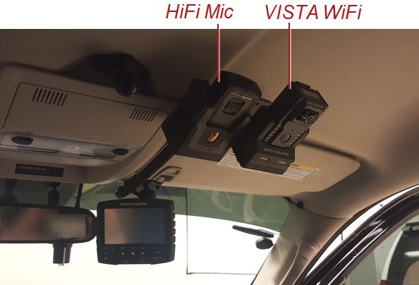
Contents

Contents

Introduction                                                5

     About this document                                     5

     Related documents and information                       6

     Installation training                                   6

Preparing for the Installation                              7

  Overview                                                   8

  Before Installing the System in a Vehicle                  9

  Standard Parts Lists                                     10

     4RE standard parts list                               10

     VISTA WiFi or VISTA XLT standard parts list           11

     V300 standard parts list                              12

  Recommended Tools                                        13

  Installation Required Practices                          14

     Cables                                                14

       HDMI cables                                         14

       Pulling cables                                      14

     Cameras                                               15

     Connections                                           15

     HiFi Microphone antenna                               15

     Power                                                 15

     Wireless radio                                        15

Installing the System                                      17

  Overview                                                 18

  Recommended Installation Workflow                        19

  Installing Cameras in the 4RE System                     23

     Installing the front camera using the puck            23

       Panoramic X2 HD                                     25

       Zero Sightline                                      25

       HD Mini Zoom                                        26

     Installing the cabin and other secondary cameras      26

4RE Vehicle Installation
                                                            iii
WGD00085 Revision F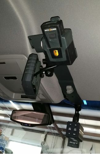
Contents

          Notes for secondary camera installation                                     27

      Installing the 4RE DVR Display                                                  28

      Installing the 4RE DVR                                                          29

      Installing a PoE adapter                                                        31

      Installing a PoE Switch                                                         33

      Installing the Wireless Radio                                                   35

        Mounting the wireless radio antenna                                           36

        MikroTik Groove                                                               39

      Installing the 4RE/VISTA or 4RE/V300 System                                     40

        Installing the Smart Power Switch                                             41

          Installing the Smart Power Switch power cable                               42

        Installing the VISTA or V300 WiFi Base                                        44

      Installing Microphones in the System                                            45

        Installing the HiFi Microphone                                                45

        Installing the cabin microphone                                               46

      Installing the GPS Antenna                                                      47

      Connecting the External Inputs Cable                                            48

      Connecting the System Power Cable to the Vehicle Battery                        50

      Testing the System Installation                                                 52

 Appendix A: Cellular LTE Upload                                                     55

 Appendix B: WatchGuard Mobile LPR                                                   56

 Index                                                                               57

                                                                 4RE Vehicle Installation
 iv
                                                                  WGD00085 Revision F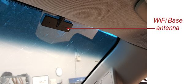
Introduction

Introduction

 Welcome to the WatchGuard 4RE Vehicle Installation Instructions. This guide is designed to
 provide basic information and instructions for installing the WatchGuard 4RE DVR and the
 VISTA or V300 body camera, with their related components, in a vehicle.

About this document
 The 4RE Vehicle Installation Instructions covers the following topics:

  l   Preparing for a vehicle installation, including:
       o   Pre-install checklist
       o   Example installation parts lists and recommended tools
       o   Installation best practices
  l   Installing WatchGuard equipment in a vehicle, including:
       o   Recommended installation workflow
       o   Cameras
       o   4RE DVR
       o   VISTA and VISTA WiFi Base or V300 and V300 WiFi Base
       o   Wireless radio
       o   Microphones
       o   Related components and cables
  l   Testing the installation

 This document also includes appendices that list basic equipment that can be added to a 4RE
 vehicle installation to provide additional functionality:

  l   Appendix A: Cellular LTE Upload
  l   Appendix B: WatchGuard Mobile LPR

 The images in this document are representative of what you could experience while installing.
 They are meant to serve as a guide.

 This guide contains general recommended instructions for installing a WatchGuard system in a
 vehicle. This document is not an exclusive or comprehensive blueprint for any particular vehicle
 installation. If you have a question about installing the system in a particular vehicle, contact
 WatchGuard Customer Service.

            Important! This document assumes knowledge of standard 12-volt vehicle
            installation best practices. It is meant to guide a technician through the specifics
            of installing WatchGuard equipment.

4RE Vehicle Installation
                                                                                                    5
WGD00085 Revision F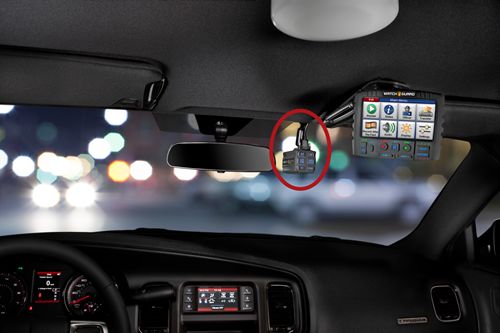
Introduction

Related documents and information
 For further information related to installing WatchGuard equipment in a vehicle that is not
 covered by the 4RE Vehicle Installation Instructions, see the following documents:

    l   4RE Installation Poster
    l   WatchGuard Bracket Guides
    l   4RE In-Car DVR User Guide
    l   VISTA HD Wearable Camera User Guide
    l   V300 Quick Start Guide
    l   Evidence Library Online Help
    l   HiFi Microphone User Guide

Installation training
 WatchGuard offers factory training courses several times per year for installers to become
 certified in WatchGuard equipment installation. For more information and to register, go to
 http://watchguardvideo.com/training.

                                                                           4RE Vehicle Installation
6
                                                                            WGD00085 Revision F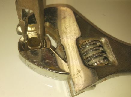
Preparing for the Installation

Preparing for the Installation

 In this section...

  l   Pre-installation checklist (page 9)
  l   Standard installation parts list examples (page 10)
  l   Recommended tools list (page 13)
  l   Installation required practices (page 14)

4RE Vehicle Installation
                                                                                      7
WGD00085 Revision F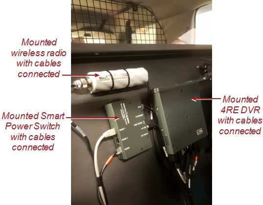
Preparing for the Installation

 Overview

  This section includes information to help you prepare for the in-vehicle installation of the
  WatchGuard 4RE DVR and the VISTA or V300 body camera and their related components. The
  section includes:

     l   Pre-installation checklist: Complete the items on this checklist before starting the
         installation (page 9)
     l   Standard installation parts lists: Contains examples of parts lists for standard 4RE/VISTA or
         4RE/V300 vehicle installations (page 10)
     l   Recommended tools list: Shows a list of tools, including some specialized items, you should
         have at hand before beginning the installation (page 13)
     l   Installation required practices: Lists a number of best practices that WatchGuard requires
         you to follow as you perform the vehicle installation (page 14)

                                                                              4RE Vehicle Installation
 8
                                                                               WGD00085 Revision F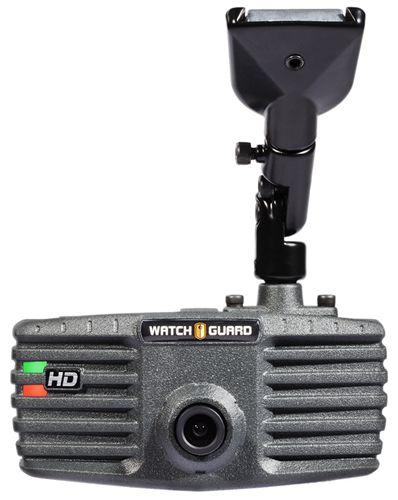
Before Installing the System in a Vehicle

Before Installing the System in a Vehicle

 Use the following list to help you prepare for a successful 4RE/VISTA or 4RE/V300 system
 installation in a vehicle:

  l   Prepare to document the installation for a first-time vehicle (year and/or model), as applicable
  l   Gather all necessary tools for the installation (page 13)
  l   Remove any old video equipment, as applicable
  l   Verify that you have received all the components for the 4RE/VISTA or 4RE/V300 system that
      you are installing (page 10)

                   Note: If you have any missing or damaged parts, contact WatchGuard
                   Customer Service.

       o   Make sure the mounting brackets are the correct type for the specific vehicle

                   Note: When installing brackets, follow the instructions included with the
                   bracket. If you need a copy of the bracket instructions, contact
                   WatchGuard Customer Service.

  l   Determine the installation locations (installation plan) for all components (including brackets
      and cables)
       o   Determine the wire connection points, for example, vehicle battery location, emergency
           light input, brake input, auxiliary input
  l   Roughly lay out the main components in their installation locations to test positioning
  l   Read through the Installation Required Practices (page 14) and add them to your installation
      plan

            Tip: Use the 4RE installation overview poster as a reference for the installation.
            You can download a copy of the installation poster from the WatchGuard Video
            website: https://support.watchguardvideo.com/hc/en-us

4RE Vehicle Installation
                                                                                                   9
WGD00085 Revision F
Preparing for the Installation

 Standard Parts Lists

  The parts lists in this section are included as examples. Your installation equipment order
  includes the actual parts list for your installation.

  If you need additional parts, contact WatchGuard Customer Service.

 4RE standard parts list
  The following table lists the standard parts included for a 4RE system installation (with wireless
  upload) in a vehicle.

       Qty   Part Number         Description

       1     WGA00428-           MikroTik Configured Wireless Kit, 4RE In-Car 802.11n (Radio,
             101                 Antenna, PoE, 2-10' Ethernet Cables)

       1     WGP01394-           Cable, WiFi Vehicle Antenna Mount, NMO, Drill 3/4" Hole, 17'
             001                 long

       1     WGA00480-           4RE, HD DVR, Gen 2, 200GB HDD
             101

       1     WGA00370-           4RE, Remote Display Control Panel, Gen 3
             200

       1     WGA00496            Front Camera, 4RE, HD Zero Sightline (ZSL)

       Or 1 WGA00543             Front Camera, 4RE, HD Panoramic

       Or 1 WGA00500             Front Camera, 4RE, HD Mini Zoom

       1     WGP01760-           Camera, Infrared Analog, WMv.2, 114 Degree, 2-Pin Connector
             200

       1     WGP01903-           Cable, 4RE, HDMI, (HD Mini Zoom, Panoramic, ZSL) Straight, 15'
             001

       1     WGP01832            Cable, 4RE, HDMI, Port 2 IR Camera, 2-Pin Connect, Straight,
                                 16' (5000mm)

       1     WGP02055-           R/A Adapter KIT, HDMI Cables, Dual Mount Bracket, 4RE DVR
             KIT

       1     WGA00382-           Cable, 4RE, HDMI/Mini, Display ONLY, Straight, 15'
             100

       1     WGA00420            Bracket Kit, 4RE, Display, w/ Diamond 1" Ball Mounts & 2" RAM

       1     WGP01459-           Bracket Kit, 4RE, Display, Universal Visor Post (Ford PI SUV &
             008-KIT             Sedan)

       1     WGP01443-           Bracket Kit, 4RE, DVR, Universal
             001-KIT

                                                                               4RE Vehicle Installation
 10
                                                                                WGD00085 Revision F
VISTA WiFi or VISTA XLT standard parts list
Qty Part Number Description
1 WGP01487- Bracket Kit, 4RE, DVR, Console Faceplate, 2"
KIT
1 WGP362 GPS Antenna, Magnetic Mount
1 WGP02073- Cable Assembly, DV-1C/4RE, Power/Input, R/A 24'
300-KIT
1 WGA00475- Hi-Fi Microphone Kit 1v.2 (Transmitter, Cradle, Belt clip, Pivot
KIT1-V2 clip, 3' + 12' antenna)
1 WGP01475 Bracket, Hi-Fi Microphone, Universal
1 WGA00510- Cable Assembly, DVR to Hi-Fi MIC, 180"
005
1 WGP412 Cabin Microphone - 7'
1 WGP412-300 Cabin Microphone Extension Cable - 12'
1 WGD00085- Kit, 4RE DVR Installation Kit
KIT
1 WGD00089- Kit, 4RE In-Car Video System User Guide
KIT
1 WGD00122 Document, Groove Setup Instructions
VISTA WiFi or VISTA XLT standard parts list
The following table lists the standard parts included when adding integrated VISTA WiFi or
VISTA XLT body camera to the 4RE system installation in a vehicle.
Qty Part Number Description
1 WGA00600 VISTA HD, WiFi Extended Wearable Camera
OR
1 VIS-XLT-WIF-001 VISTA XLT Wi-Fi System Body-Mounted Camera Kit
OR
1 VIS-XLT-WIF-002 VISTA XLT Wi-Fi System Head-Mounted Camera Kit
1 WGA00586-KIT VISTA HD, WiFi Charging Radio Base Kit, incl. Power and
Cables
1 WGA00574 4RE, VISTA HD WiFi, Smart PoE Switch
1 WGP02225-203-KIT Bracket, VISTA WiFi base Universal, All-In-One, with
Screws
1 WGP02225-202-KIT Bracket Kit, Wi-Fi Base, Universal w/ screws
4RE Vehicle Installation
11
WGD00085 Revision FPreparing for the Installation
V300 standard parts list
The following table lists the standard parts included when adding the V300 body camera to the
4RE system installation in a vehicle.
Qty Part Number Description
1 WGA00625 V300 Wearable Camera
1 WGA00635-KIT V300 WiFi Dock, D330, In-Vehicle Charge/Upload Kit, incl.
Cables and Brackets
1 WGA00635 V300 Base Assembly, WiFi Dock
1 WGP02494 Cable Assembly, Bullet to Antenna, Smart POE Switch
1 WGP02495 Cable Assembly, Power, Smart POE Switch
1 WGP02791 Cable Assembly, RJ50 10P10C, Straight, 25FT, G2 Wear, WiFi
Base
1 WGP01090-001 Cable Assembly, Straight Ethernet, CAT5E, 5FT
1 WGP584-102 Cable Assembly, Fused, +12V, 7.5 AMP
1 WGP587-103 Cable Assembly, Battery Ground 16 AWG, 16IN
1 WGP582-002 Fuse, ATO/ATC, 7.5 AMP
1 WGP02504 Antenna, Windshield Mount, 2.4 GHz, 3FT, VISTA WiFi Base
1 WGP01573-400 Extension Cable, PFP195, 12FT, PCTEL WiFi Antenna to
VISTA WiFi Base
1 WGP02225-202- Bracket Kit, WiFi Base, Universal, w/ Screws
KIT
1 WGP02225-203- Bracket Kit, WiFi Base, Offset, w/ Screws
KIT
4RE Vehicle Installation
12
WGD00085 Revision FRecommended Tools
Recommended Tools
The following tools are recommended for installing the 4RE DVR and VISTA or V300 body
camera and their related components in a vehicle.
l Drill and bits, including 3/4-inch bit for antenna mounting
l Coarse sandpaper, 60 or 80 grain
l 10-30 feet of 16-20 gauge primary wire for extending input cable connections if necessary
l Wire strippers
l Wire crimpers
l Various wrenches and sockets, including 24mm or 15/16-inch open-ended wrench
l Pliers
l Utility knife
l Torx® screwdrivers or bits, sizes T20, T15, and T10
l 1/16-inch hex screwdriver or Allen® wrench
l Electrical tape and/or heat-shrink tubing
l Zip ties
l Hand-held butane torch or lighter (Optional)
l Loctite® 312 adhesive and primer
l 3M™ Scotch® Super 33+™ tape
4RE Vehicle Installation
13
WGD00085 Revision FPreparing for the Installation
Installation Required Practices
Important! These practices are required by WatchGuard. Using them helps you
have a more successful installation experience.
Cables
HDMI cables
Important! The HDMI cables included with the WatchGuard installation kits are
customized to be as rugged as possible; however, HDMI cables are very
susceptible to damage. They do not work if kinked or pinched.
Keep the following required practices in mind when working with the system HDMI cables:
l Be careful of cable bends—use no more than a soft S-bend
l Leave the plastic caps on the cable ends until you are ready to connect them to a component
l Use the 10 VELCRO® strips included with each system when you install the HDMI cables
l If you use zip ties on HDMI cables, make the loops loose enough to allow the cable or cable
bundle to barely spin in the loop
Zip ties that are pulled too tight damage HDMI cables. Be careful not to damage the HDMI
cables if you use a zip tie gun.
Tip: If you are mounting the 4RE DVR in the console, you may need to use the
HDMI right-angle adapter kit to avoid making sharp bends in the HDMI cables
where they connect to the 4RE DVR. For more information and to order the kit,
contact WatchGuard Customer Service.
Pulling cables
Pulling cables in the vehicle can be difficult and can damage the cables. Order and install new
cables if you move a system from one vehicle to another.
4RE Vehicle Installation
14
WGD00085 Revision FCameras
Cameras
If you plan to mount the front camera on a puck, install the puck on the windshield first to allow
the glue to dry.
Tip: You can use a hand-held butane torch or lighter to heat the puck. This can
help speed up the installation process (page 23).
Connections
l Always butt-splice and crimp wire connections
Important! Do not use 3M™ ScotchLok™ or similar types of connectors.
l Use 3M Scotch® Super 33+™ tape to cover any soldered electrical connections
HiFi Microphone antenna
Always position and install the HiFi Microphone (HiFi Mic) antenna horizontally. The antenna
inside the HiFi Mic transmitter is horizontal. For good performance, you should mount the HiFi
Mic antenna horizontally to match.
Warning! Do not follow the manufacturer's online specifications for installing
the antenna vertically. If you mount the antenna vertically, the HiFi Mic loses 90
percent of its operational range.
Power
Wire power to the battery. The battery is the cleanest source of power in the vehicle.
Wireless radio
Always mount the wireless radio in a position where you can easily see its LEDs. Access to the
LEDs is needed for diagnostic purposes.
Important! Do not mount the wireless radio in a location that is difficult to
access, for example, in the console.
4RE Vehicle Installation
15
WGD00085 Revision FPreparing for the Installation
This page intentionally left blank.
4RE Vehicle Installation
16
WGD00085 Revision FInstalling the System
Installing the System
In this section...
l Recommended installation workflow (page 19)
l Installation information and procedures for:
o Front and secondary cameras (page 23)
o 4RE DVR (page 29) and its display (page 28)
o PoE (power over Ethernet) adapter (page 31) and switch (page 33)
o Smart Power Switch (page 41)
o Wireless radio and its antenna (page 35)
o Wireless and cabin microphones (page 45)
o VISTA or V300 WiFi Base (page 44)
o GPS antenna (page 47)
o Connecting the system to external inputs (page 48)
o Connecting power to the 4RE (page 50)
o Connecting power to the Smart Power Switch (page 42)
l Testing the 4RE/VISTA or 4RE/V300 installation (page 52)
4RE Vehicle Installation
17
WGD00085 Revision FInstalling the System
Overview
This section includes a full system installation workflow (page 19). WatchGuard recommends
that you follow this workflow for best results.
It also includes individual sections for installing the following components:
l Front and secondary cameras (page 23)
l 4RE DVR (page 29) and its display (page 28)
l PoE (power over Ethernet) adapter (page 31) and switch (page 33)
l Smart Power Switch (page 41)
l Wireless radio and its antenna (page 35)
l Wireless and cabin microphones (page 45)
l VISTA or V300 WiFi Base (page 44)
l GPS antenna (page 47)
l Connecting the system to external inputs (page 48)
l Connecting power to the 4RE (page 50)
l Connecting power to the Smart Power Switch (page 42)
The final section provides instructions for testing the 4RE installation (page 52).
4RE Vehicle Installation
18
WGD00085 Revision FRecommended Installation Workflow
Recommended Installation Workflow
The following steps make up a recommended workflow for installing the 4RE DVR and the
VISTA or V300 body camera with their related components:
Warning! Only connect cables when this workflow instructs you to. Connecting
cables out of sequence can damage components.
1. Complete all items in the Before Installing the 4RE System in a Vehicle list (page 9).
2. Remove vehicle panels, as needed.
3. Remove cables from their packaging, and roughly lay them throughout the vehicle to verify
routing and length.
Note: If a cable is too short, contact WatchGuard customer service for a
longer cable.
4. Install the front camera (page 23):
a. If you are using a puck (rearview mirror button), glue the puck to the windshield.
(page 23)
If you are using a front camera bracket, install the bracket then attach the camera
to it.
b. Connect the HDMI cable to the front camera then run it to the location where you will
install the 4RE DVR, but DO NOT connect the cable to the 4RE.
5. Install the 4RE Display (page 28):
a. Position and install the display bracket.
b. Install the bracket-side RAM® ball on the display bracket.
c. On the back of the display, connect the HDMI cable.
d. Install the display-side RAM bracket and ball on the back of the display.
e. Attach the display to the display bracket using the RAM ball mount.
f. Run the HDMI cable to the DVR location, but DO NOT connect it to the 4RE DVR.
6. Install the 4RE DVR (page 29):
a. Install the DVR bracket.
b. Position and loosely install the DVR, but DO NOT connect cables to it.
4RE Vehicle Installation
19
WGD00085 Revision FInstalling the System
7. Perform one of the following options, depending on the equipment you have:
If you have a wireless radio kit, position and install (but DO NOT connect cables):
o PoE (power over Ethernet) adapter (page 31) or PoE switch (page 33)
Note: If you have a switch in your set of components to be installed,
you should install the switch, not the adapter.
o Wireless radio (page 35)
If you have a wireless radio kit AND a VISTA WiFi or V300 kit, position and install
(but DO NOT connect cables):
o Smart Power Switch (page 41)
o Wireless radio (page 35)
If you have a VISTA WiFi or V300 kit but NO wireless radio kit, position and install
(but DO NOT connect cables):
o Smart Power Switch (page 41)
If you have a mobile data computer (MDC) kit, and/or a modem, AND a
VISTA WiFi or V300 kit, position and install (but DO NOT connect cables):
o Smart Power Switch (page 41)
If you have an MDC kit, and/or a modem, but NO VISTA WiFi or V300 kit, position
and install (but DO NOT connect cables):
o PoE switch (page 33)
8. If you have a wireless radio kit, install the wireless radio antenna and the radio-to-4RE
Ethernet cables:
a. Mount (drilled, magnetic, or trunk mount) the wireless radio antenna cable then run it to
the wireless radio. (page 36)
b. Connect the antenna cable to the wireless radio.
c. Connect an Ethernet cable from the wireless radio to the Radio connector port on the PoE
adapter/switch or the Smart Power Switch.
d. Connect an Ethernet cable from the DVR connector port on the PoE adapter/switch or the
Smart Power Switch to the Ethernet port on the 4RE DVR.
9. If you have a VISTA WiFi or V300 kit but NO wireless radio kit, connect an Ethernet
cable from the DVR connector port on the Smart Power Switch to the Ethernet port on the
4RE DVR.
10. If you have an MDC kit, connect an Ethernet cable from one of the following switch
connector ports to the MDC/laptop:
o PoE switch: One of the numbered connector ports (for example, Port 1)
o Smart Power Switch: Ethernet connector port
11. If you have a modem, connect an Ethernet cable from one of the following switch
connector ports to the modem:
o PoE switch: One of the numbered connector ports (for example, Port 2)
o Smart Power Switch: Base 2 or Ethernet connector port (whichever is available)
4RE Vehicle Installation
20
WGD00085 Revision FRecommended Installation Workflow
12. If you have a HiFi Microphone kit, install the HiFi Mic and its related components (page
45):
a. Position and install the HiFi Mic antenna on the windshield.
Note: You may need to install two HiFi Mics in some vehicles. For
information on antenna placement in this case, see the HiFi
Microphone User Guide.
b. Install the HiFi Mic bracket and attach the HiFi Mic base to it.
c. Connect the HiFi Mic antenna cable to the HiFi Mic base.
d. Connect the HiFi Mic cable to the HiFi Mic base then run it to the 4RE DVR location (but DO
NOT connect the cable).
13. If you have a VISTA WiFi or V300 kit, install the VISTA or V300 WiFi Base and its related
components (page 44):
a. Position and install the WiFi Base antenna on the windshield.
b. Install the WiFi Base bracket and attach the WiFi Base to it.
c. Connect the WiFi Base antenna cable to the WiFi Base.
d. Connect the WiFi Base cable to the WiFi Base, run it to the Smart Power Switch, then
connect it to the Base 1 connector port on the switch.
14. Install the cabin microphone and run its cable to the 4RE DVR location (but DO NOT connect
the cable). (page 46)
15. Install the GPS antenna and run its cable to the 4RE DVR location (but DO NOT connect the
cable). (page 47)
16. Install the cabin camera and any other secondary cameras, then run their cables to the
4RE DVR location (but DO NOT connect the cables). (page 26)
17. Position the external inputs cable part of the power and external inputs harness (page 48):
a. Run the DVR connector end of the power and external inputs harness to the 4RE DVR
location, but DO NOT connect the harness to the 4RE.
b. Run the external inputs cable to the best location for the vehicle, according to your
installation plan.
c. If you installed a PoE adapter (page 31) or a PoE switch (page 33), connect the
orange and brown wires from the external inputs cable to the appropriate component.
d. Connect each remaining sense wire in the external inputs cable to the corresponding
external device input wire, as needed. (page 49)
18. Install the system power cable part of the power and external inputs harness (but DO NOT
insert the 7.5 amp fuse in the fuse holder) (page 50):
a. Run the power cable to the vehicle battery location.
b. Connect the red and black wire extensions to the red and black (and drain) wires in the
power cable.
c. Connect the red and black ring terminals to the appropriate vehicle battery posts, but
DO NOT insert the 7.5 amp fuse in the fuse holder.
4RE Vehicle Installation
21
WGD00085 Revision FInstalling the System
19. If you installed a Smart Power Switch, install the Smart Power Switch power cable (but
DO NOT insert the 7.5 amp fuse in the fuse holder) (page 42).
a. Position the Smart Power Switch end of the power cable near the Smart Power Switch
location, but DO NOT connect it to the switch.
b. Run the power cable to the vehicle battery location.
c. Connect the red and black wire extensions to the red and black wires in the power cable, as
needed.
d. Connect the red and black ring terminals to the appropriate vehicle battery posts, but DO
NOT insert the 7.5 amp fuse in the fuse holder.
20. Connect the following cables to the 4RE DVR, as applicable:
a. Cabin microphone cable to the Cab Mic connector port
b. Display HDMI cable to the Display connector port
c. All camera cables to their appropriate connector ports
d. HiFi Microphone cable to the Wireless Mic connector port
e. GPS cable to the GPS connector port
Note: If you are mounting the 4RE DVR in the console, you may need to
use the HDMI right-angle adapter kit to avoid making sharp bends in the
HDMI cables where they connect to the 4RE DVR. For more information
and to order the kit, contact WatchGuard Customer Service.
21. If you installed a Smart Power Switch, connect the Smart Power Switch power cable to
the +12 VDC connector port on the switch.
22. Connect the system power and external inputs harness to the External
Inputs/Power connector port on the 4RE DVR.
23. If you installed a Smart Power Switch, insert the 7.5 amp fuse into the Smart Power
Switch power cable fuse holder.
24. Insert the 7.5 amp fuse into the system power cable fuse holder.
25. Test the installation (page 52).
4RE Vehicle Installation
22
WGD00085 Revision FInstalling Cameras in the 4RE System
Installing Cameras in the 4RE System
The 4RE Standard system can have up to three cameras in an installation, one front camera
and two secondary cameras. The 4RE Elite system can have up to six cameras in an
installation, one front camera and five secondary cameras.
WatchGuard offers three types of front camera:
l ZSL (Zero Sightline) (page 25)
l Panoramic X2 HD (page 25)
The Panoramic X2 HD counts as two cameras in the installation, one front camera and one
secondary camera.
l Mini-Zoom (page 26)
Each type is mounted either with a puck (rearview mirror button) adhered to the windshield
(below) or to a bracket.
A vehicle installation typically includes one secondary camera facing the back seat (cabin
camera), but it can include up to five secondary cameras. (page 26)
Installing the front camera using the puck
If you are using a puck (rearview mirror button) to install the front camera, attach the puck to
the windshield using Loctite® 312 adhesive.
Tip: You can use a hand-held butane torch or lighter to heat the puck. This can
help speed up the installation process.
1. Clean the windshield surface using a microfiber cloth (or something similar), and alcohol or
window cleaner.
2. Clean any residue from the puck, using alcohol or window cleaner.
Important! DO NOT score the surface of the puck. Scoring the puck can
keep it from properly adhering to the windshield.
3. Place the puck in the front camera mount.
Tip: Do not over-tighten the mount to the puck. Over-tightening causes
a slight curve in the puck that keeps it from adhering properly to the
windshield.
4RE Vehicle Installation
23
WGD00085 Revision FInstalling the System
4. Determine where exactly on the windshield you want to mount the front camera.
Note: Place the puck as high as possible on the windshield for a better
viewing angle.
5. (Optional) Heat the puck for 10 to 15 seconds, using a lighter or a hand-held butane torch,
until it is warm to the touch.
Note: Wipe off any black residue left from the lighter flame.
The color of the puck changes slightly when it is heated.
6. Carefully spray Loctite® primer on the puck AND the windshield (1 or 2 sprays to cover the
area where you are mounting the puck).
7. Let the primer dry.
8. Apply a drop (5/16-inch or pea size) of the Loctite adhesive to the puck.
Tip: Apply enough adhesive that it spreads to every corner of the puck
when you press the puck to the glass.
9. Quickly press the puck with the camera attached to the windshield and hold it there for 60
seconds.
10. Leave the camera in place for at least 10 minutes to allow the adhesive to dry completely.
Note: If the puck does not successfully adhere to the windshield, replace
the used puck with a new one and try again.
11. Connect the HDMI cable to the front camera then run the cable to the 4RE DVR location (but
DO NOT connect the cable to the 4RE).
12. When instructed to do so in the full installation workflow on page 22, connect the front
camera HDMI cable to the Front connector port on the 4RE DVR.
Important! Only connect cables when the full installation workflow on
page 19 instructs you to. Connecting cables out of sequence can
damage components.
4RE Vehicle Installation
24
WGD00085 Revision FPanoramic X2 HD
Panoramic X2 HD
The Panoramic X2 HD contains two cameras: a rotatable HD (high
definition) camera that functions as the front camera in the vehicle,
and a fixed panoramic camera that has a very wide field of view and
functions as a secondary camera.
You can mount the Panoramic X2 HD camera using one of two
options:
l Puck mounted to the windshield just behind the rearview
mirror (page 23)
l Bracket mounted to the passenger visor post
Zero Sightline
The Zero Sightline (ZSL) is an HD (high definition) camera that
functions as the front camera in the vehicle. It typically mounts in
front of the rearview mirror so it does not obstruct the officer's line of
sight.
You can mount the ZSL camera using one of two options:
l Puck mounted to the windshield just behind the rearview
mirror (page 23)
l Bracket mounted to the passenger visor post
4RE Vehicle Installation
25
WGD00085 Revision FInstalling the System
HD Mini Zoom
The HD Mini Zoom camera is an HD (high definition) camera that
functions as the front camera in the vehicle. It features a 12X optical
zoom.
You can mount the HD Mini Zoom camera using one of two options:
l Puck mounted to the windshield about one inch to the right of
the rearview mirror (page 23)
l Bracket mounted to the passenger visor post
Installing the cabin and other secondary cameras
Typically, a vehicle installation includes one secondary camera facing the back seat (cabin
camera), but an installation can have up to five secondary cameras.
To install the cabin and other secondary cameras:
1. Mount each secondary camera according to your installation plan.
2. Connect each camera's cable to the camera then run it to the 4RE DVR location but DO NOT
connect the cables to the 4RE.
3. When instructed to do so in the full installation workflow on page 22, connect the secondary
camera cables to the appropriate connector ports on the 4RE DVR.
4RE Vehicle Installation
26
WGD00085 Revision FNotes for secondary camera installation
Notes for secondary camera installation
Where you connect the secondary cameras to the 4RE DVR depends on which cameras and
which version of the 4RE are part of the installation. For two examples of 4RE DVR connections,
see Installing the 4RE DVR on page 29.
Keep the following items in mind when you install secondary cameras:
l If you installed a Panoramic X2 HD camera as your front camera OR you have an Auxiliary
Cameras connector port (mezzanine card) on the 4RE DVR, you can only connect one camera
to port 2 (you cannot use a splitter on camera port 2)
l If you installed a Panoramic X2 HD camera as your front camera AND you have an Auxiliary
Cameras connector port (mezzanine card) on the 4RE DVR, you cannot use camera port 2
If you need more information about connecting secondary cameras to the 4RE, contact
WatchGuard customer service.
4RE Vehicle Installation
27
WGD00085 Revision FInstalling the System
Installing the 4RE DVR Display
Typically you mount the 4RE Display on a bracket using a RAM® ball mount. The mount has
two main parts: a ball that attaches to the display bracket and a ball that attaches to the back of
the display. A joint connects the two parts of the mount together.
Tip: Where you mount the 4RE DVR Display varies from vehicle to vehicle. For
more information, see the mounting instructions included with the brackets.
To install the 4RE DVR Display:
1. Position and install the display bracket.
Note: You may have already installed the display bracket when you
installed the front camera bracket.
2. Attach the bracket-side part of the display mount to the display bracket.
3. Remove the back panel from the display and connect the display HDMI cable.
4. Replace the back panel on the display.
Important! Make sure that you do not pinch the HDMI cable when you
replace the back panel on the display.
5. Attach the display-side RAM bracket and ball to the back of the display.
6. Attach the display to the display bracket using the mount knuckle joint to connect the two
mount parts together.
7. Run the display HDMI cable to the 4RE DVR location, but DO NOT connect it to the DVR.
8. When instructed to do so in the full installation workflow on page 22, connect the display
HDMI cable to the 4RE DVR.
Important! Only connect cables when the full installation workflow on
page 19 instructs you to. Connecting cables out of sequence can
damage components.
4RE Vehicle Installation
28
WGD00085 Revision FInstalling the 4RE DVR
Installing the 4RE DVR
How and where you mount the 4RE DVR depends on agency preference as well as the vehicle
where you are installing the system. The most common locations for mounting the 4RE DVR
include:
l Behind the front seat (photo below)
l In the console
l On an equipment tray in the trunk
To install the 4RE DVR:
1. Install the 4RE DVR bracket.
Note: For information about installing the DVR bracket for a particular
vehicle, see the mounting instructions included with the bracket.
2. Position and loosely install the 4RE DVR, but DO NOT connect cables to it.
Important! Only connect cables when the full installation workflow on
page 19 instructs you to. Connecting cables out of sequence can
damage components.
4RE Vehicle Installation
29
WGD00085 Revision FInstalling the System
3. When instructed to do so in the full installation workflow on page 22, connect cables to the
back of the 4RE DVR.
Tip: If you are mounting the 4RE DVR in the console, you may need to
use the HDMI right-angle adapter kit to avoid making sharp bends in the
HDMI cables where they connect to the 4RE DVR. For more information
and to order the kit, contact WatchGuard Customer Service.
Note: The 4RE DVR you are installing is one of multiple possible
versions. Two of the most common variations are pictured above.
4RE Vehicle Installation
30
WGD00085 Revision FInstalling a PoE adapter
Installing a PoE adapter
Important! If the system you are installing includes the integrated VISTA or
V300 body camera and 4RE DVR components, you must install the Smart Power
Switch instead of the PoE adapter. For more information and instructions, see
Installing the 4RE/VISTA or 4RE/V300 System on page 40.
If you are installing a wireless radio in the system, you
need to install and connect the PoE (power over Ethernet)
adapter. The PoE adapter allows the 4RE DVR to provide
power and the data connection for the wireless radio.
Typically you mount the adapter within a few feet of the wireless radio, for example, behind the
seat.
Note: If you need to include an MDC (mobile data computer) or modem in the
system, you need to install a PoE switch instead of the adapter. For instructions
how to install the PoE switch, see Installing a PoE Switch on page 33.
4RE Vehicle Installation
31
WGD00085 Revision FInstalling the System
To connect the PoE adapter into the system and to the radio:
1. Mount the adapter according to your installation plan, but DO NOT connect any cables.
Important! Only connect cables when the full installation workflow on
page 19 instructs you to. Connecting cables out of sequence can
damage components.
2. Locate the two Ethernet cables included in the DVR installation kit.
3. Connect the following cables ONLY when instructed to do so in the full installation workflow on
page 20:
a. Connect one Ethernet cable from the Radio connector port on the PoE adapter to the
wireless radio.
Warning! DO NOT plug in the wireless radio's PoE connector
(Ethernet connection) and power up the radio WITHOUT an antenna
connected. Powering up the radio without an antenna can damage
the radio.
b. Connect the other Ethernet cable from the DVR connector port on the PoE adapter to the
4RE DVR.
Warning! Make sure you connect the Ethernet cables to the correct
ports on the PoE adapter. Plugging the cables in backwards will
damage the Ethernet port on the 4RE DVR.
4. After running the external inputs cable (and when instructed to do so in the full installation
workflow on page 21), insert the orange (positive 12 volt power) and brown (ground) wires
from the external inputs cable into the appropriate labeled holes on the adapter, then tighten
down the screws.
Note: For more information on connecting the wires from the external
inputs cable, see Connecting the External Inputs Cable on page 48.
4RE Vehicle Installation
32
WGD00085 Revision FInstalling a PoE Switch
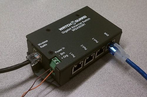
Installing a PoE Switch
Important! If the system you are installing includes the integrated VISTA WiFi
and 4RE DVR components, you must install the Smart Power Switch instead of
the PoE switch. For more information and instructions, see Installing the
4RE/VISTA or 4RE/V300 System on page 40.
If you need to include an MDC (mobile data
computer), laptop, or modem (for example, Sierra
Wireless®) in the system as well as a wireless radio,
you need to install and connect the PoE (power over
Ethernet) switch. The PoE switch allows the 4RE
DVR to provide power and a data connection for the
wireless radio as well as an additional data
connection for the MDC/laptop or modem.
Typically you mount the PoE switch within a few feet of the wireless radio, for example, behind
the seat.
Note: If you do not need to include an MDC (mobile data computer) or modem in
the system, you only need to install a PoE adapter instead of the switch. For
instructions how to install the adapter, see Installing a PoE adapter on page 31.
4RE Vehicle Installation
33
WGD00085 Revision FInstalling the System
To connect the PoE switch into the system:
1. Mount the switch according to your installation plan, but DO NOT connect any cables.
Important! Only connect cables when the full installation workflow on
page 19 instructs you to. Connecting cables out of sequence can
damage components.
2. Locate the two Ethernet cables included in the DVR installation kit and the additional Ethernet
cables included with the MDC package and/or modem.
3. Connect the following cables ONLY when instructed to do so in the full installation workflow on
page 19:
a. Connect one Ethernet cable from the Wireless Radio connector port on the PoE switch to
the wireless radio.
Warning! DO NOT connect the wireless radio's Ethernet connection
or power up the radio WITHOUT an antenna connected. Powering up
the radio without an antenna can damage the radio.
b. Connect one Ethernet cable from the DVR connector port on the PoE switch to the 4RE
DVR.
Warning! Make sure you connect the Ethernet cables to the correct
ports on the PoE switch. Plugging the cables into the wrong ports will
damage the Ethernet port on the 4RE DVR.
c. As needed, connect one Ethernet cable from any of the numbered ports on the PoE switch
to the MDC/laptop (or laptop docking station).
Warning! Make sure you only connect the MDC/laptop to one of the
numbered ports on the PoE switch. Plugging the MDC cable into the
wrong port on the switch will damage the MDC/laptop.
d. As needed, connect one Ethernet cable from any of the numbered ports on the PoE switch
to the modem.
4. After running the external inputs cable (and when instructed to do so in the full installation
workflow on page 21), insert the orange (positive 12 volt power) and brown (ground) wires
from the external inputs cable into the appropriate labeled holes on the switch, then tighten
down the screws.
Note: For more information on connecting the wires from the external
inputs cable, see Connecting the External Inputs Cable on page 48.
4RE Vehicle Installation
34
WGD00085 Revision FInstalling the Wireless Radio
Installing the Wireless Radio
Important! WatchGuard recommends that wireless radios be configured before
you mount them in the vehicle. Typically, radios purchased from WatchGuard are
configured before they leave the factory. If you have chosen to configure your
own wireless radios, before starting the configuration process, contact
WatchGuard Customer Service for instructions.
WatchGuard provides the following type of wireless radio:
l MikroTik Groove (page 39)
Note: If you are reinstalling older equipment, you may have a Ubiquiti® Bullet™
radio. If you need information or instructions specific to the Bullet radio, contact
WatchGuard Customer Service.
Typically you mount the wireless radio near the switch and/or 4RE DVR, for example, behind
the front seat, using zip ties.
Note: No mounting hardware is included with the wireless radio.
4RE Vehicle Installation
35
WGD00085 Revision FInstalling the System
To install the wireless radio:
1. Mount the wireless radio according to your installation plan, but DO NOT connect any cables.
Important! Make sure you mount the wireless radio in a position where
you can easily see its LEDs. The LEDs are needed for diagnostic purposes.
2. Mount the wireless radio antenna. (below)
3. Run the antenna cable to the wireless radio then connect it.
Warning! DO NOT plug in the wireless radio's PoE connector (Ethernet
connection) and power up the radio WITHOUT an antenna connected.
Powering up the radio without an antenna can damage the radio.
4. When instructed to do so in the full installation workflow on page 20, connect an Ethernet
cable from the radio connector port on the switch or the PoE adapter to the wireless radio.
Warning! Make sure you connect the Ethernet cable to the correct port
on the switch or adapter. Plugging the cables into the wrong ports will
damage the Ethernet port on the 4RE DVR.
Mounting the wireless radio antenna
Typically, you mount the radio antenna on the roof or trunk of the vehicle.
Important! WatchGuard recommends that you keep 9 inches between the
wireless radio antenna and other antennas. You must keep a minimum of 6
inches between antennas.
You route the antenna cable into the vehicle to the location where you plan to mount the
wireless radio. You can choose from two different types of radio antenna mounts:
l Through-hole antenna (NMO mount) which requires that you drill a 3/4-inch hole through the
vehicle roof
The example installation in this section shows an NMO mount antenna.
l Magnetic mount which does not require that you drill a hole
Important! WatchGuard Video recommends that you use the NMO mount
antenna because it provides better signal strength.
4RE Vehicle Installation
36
WGD00085 Revision FMounting the wireless radio antenna
To install an NMO mount radio antenna:
1. Access the roof of the vehicle in your preplanned location (for example, through the rear seat
dome light or by removing the headliner).
2. Drill a 3/4-inch hole for the antenna cable.
3. Sand the paint off the metal around the interior hole to ensure a good ground.
4. Remove the NMO nut from the radio antenna cable.
5. Starting with the radio-connector end, feed the antenna cable through the exterior hole in the
vehicle until only the antenna mount (NMO-connector) end of the cable remains outside the
vehicle.
6. Tilt the antenna mount end to guide it through the exterior hole, then center the flange in the
hole.
7. Make sure that the antenna mount ridges are in contact with the bare metal (from your
sanding) inside the vehicle.
4RE Vehicle Installation
37
WGD00085 Revision FInstalling the System
8. On the antenna mount outside the vehicle, reattach the NMO nut, with the O-ring facing down
to create a seal.
9. Tighten the nut with a 24mm or 15/16-inch open-end wrench, making sure that the mount
stays centered in the hole and does not turn and kink the cable.
Tip: To keep the cable from turning and kinking, use needle-nose pliers
in the holes on the antenna mount to anchor the mount while you
tighten the NMO nut.
Warning! DO NOT tighten the NMO nut using channel-lock pliers.
Tightening the NMO nut using a channel-lock pliers can damage the nut
and cause an unreliable wireless signal.
10. Inside the vehicle, route the radio-connector end of the antenna cable to the location where
you plan to mount the radio, making sure that you leave enough slack to avoid kinks.
11. Attach the antenna connector to the radio.
Warning! DO NOT plug in the wireless radio's PoE connector (Ethernet
connection) and power up the radio WITHOUT an antenna connected.
Powering up the radio without an antenna can damage the radio.
4RE Vehicle Installation
38
WGD00085 Revision FMikroTik Groove
MikroTik Groove
Warning! Do not connect the wireless radio's Ethernet connection or power up
the radio without an antenna connected. Powering up the radio without an
antenna can damage the radio.
To verify that the MikroTik Groove wireless radio is working properly, check the LEDs on the side
of the device:
l Power/Connectivity LED: When lit, shows that the radio has power and is connected to the
4RE DVR system
Tip: To see whether the Groove radio is communicating successfully with
the 4RE DVR, after the 4RE is configured, navigate to the Wireless
screen on the 4RE (press Menu on the Control Panel, then touch
Settings > Diagnose > Wireless on the Screen) and look for the
Access Connected value. If the value is Yes, the Groove radio can see
the 4RE to communicate with it.
l Signal strength LEDs: When lit, shows that the radio is associated with the agency's access
point
All of the LEDs on the Groove radio are green when lit. The signal between the radio and the
access point is strongest when all five signal-strength LEDs are lit.
4RE Vehicle Installation
39
WGD00085 Revision FInstalling the System
Installing the 4RE/VISTA or 4RE/V300 System
If your vehicle installation includes the VISTA or V300 body camera with the 4RE, you need to
install:
l Smart Power Switch (page 41)
l VISTA or V300 WiFi Base (page 44)
The Smart Power Switch is typically mounted near the 4RE DVR. The WiFi Base is typically
mounted on or near the passenger visor post.
Important! Only connect cables when the full installation workflow on page 19
instructs you to. Connecting cables out of sequence can damage components.
4RE Vehicle Installation
40
WGD00085 Revision FInstalling the Smart Power Switch
Installing the Smart Power Switch
If the system you are installing includes
the VISTA or V300 body camera and 4RE
DVR components, you must install the
Smart Power Switch instead of the PoE
(power over Ethernet) switch (page 33)
or adapter (page 31).
The Smart Power Switch is required for the
integrated body camera and 4RE to form a
recording group. As part of the local
recording group network, the Smart Power
Switch:
l Functions as the central connection
point
l Intelligently manages power
l Functions as the local network DHCP
server
Typically you mount the Smart Power Switch within a few feet of the wireless radio, for
example, in the console or behind the seat.
Note: For a cabling diagram showing the 4RE/VISTA or 4RE/V300 system, see
Installing the 4RE/VISTA or 4RE/V300 System on page 40.
To connect the Smart Power Switch into the system:
1. Mount the switch according to your installation plan, but DO NOT connect any cables.
Important! Only connect cables when the full installation workflow on
page 19 instructs you to. Connecting cables out of sequence can
damage components.
2. Locate the two Ethernet cables included in the DVR installation kit and the additional Ethernet
cables (as needed) for the MDC package or modem (for example, Sierra Wireless®).
3. Connect the following cables only when instructed to do so in the full installation workflow on
page 20:
a. Connect one Ethernet cable from the Radio connector port on the Smart Power Switch to
the wireless radio.
Warning! Do not connect the wireless radio's Ethernet connection
or power up the radio without an antenna connected. Powering up
the radio without an antenna can damage the radio.
4RE Vehicle Installation
41
WGD00085 Revision FInstalling the System
b. Connect one Ethernet cable from the DVR connector port on the Smart Power Switch to
the 4RE DVR.
Warning! Make sure you connect the Ethernet cables to the correct
ports on the Smart Power Switch. Plugging the cables into the wrong
ports will damage the Ethernet port on the 4RE DVR.
c. As needed, connect one Ethernet cable from the Ethernet connector port on the Smart
Power Switch to the MDC/laptop.
Note: If you are installing a laptop docking station, connect the cable
from the switch to the Ethernet port on the docking station. For
more information, see the manufacturer's documentation for the
docking station.
Warning! Make sure you only connect the MDC/laptop to the
Ethernet connector port on the Smart Power Switch. Plugging the
MDC cable into the wrong port on the switch will damage the
MDC/laptop.
d. As needed, connect one Ethernet cable from either the Ethernet or the Base 2 connector
port (whichever is available) on the Smart Power Switch to the modem.
4. After running the WiFi Base cable (and when instructed to do so in the full installation workflow
on page 21), connect the base cable to the Base 1 connector port on the Smart Power
Switch.
5. When instructed to do so in the full installation workflow on page 22, install the Smart Power
Switch power cable (below).
Installing the Smart Power Switch power cable
Warning! Only connect cables when the full installation workflow on page 19
instructs you to. Connecting cables out of sequence can damage components.
When you install the Smart Power Switch power cable, connect it directly to the vehicle battery.
To install the Smart Power Switch power cable:
1. Route the power cable to the vehicle battery.
Important! Use the firewall holes and grommets provided by the
vehicle manufacturer to route the cable to the battery. Consult your
vehicle manufacturer's documentation for specific information.
2. Pull the power cable, including any excess cable, toward the battery, leaving some slack for a
drip loop.
4RE Vehicle Installation
42
WGD00085 Revision FInstalling the Smart Power Switch power cable
3. Wind up and tie off or cut the excess power cable.
4. Strip back the sheath on the power cable and its red (positive) and black (ground) wires.
5. Crimp the black (ground) wire to the provided black (ground) wire extension with the attached
ring terminal.
Tip: Use butt splices when you connect the wires to ensure good
connection.
6. Crimp the red (positive) wire to the provided red (positive) 7.5 amp fuse holder with the
attached ring terminal but DO NOT insert the 7.5 amp fuse in the fuse holder.
7. Connect the red (positive) and black (ground) ring terminals to their vehicle battery posts.
8. When instructed to do so in the full installation workflow on page 22, connect the Smart
Power Switch power cable to the +12 VDC connector port on the Smart Power Switch.
9. When instructed to do so in the full installation workflow on page 22, insert the 7.5 amp fuse
in the fuse holder.
Warning! DO NOT insert the 7.5 amp fuse until you have finished
installing and connecting all the system equipment. Inserting the fuse
before you finish the full installation can damage the system.
4RE Vehicle Installation
43
WGD00085 Revision FInstalling the System
Installing the VISTA or V300 WiFi Base
If the system you are installing includes the VISTA
WiFi or V300 kit, you must install the VISTA or V300
WiFi Base.
The WiFi Base is required for the integrated body
camera and 4RE DVR to form a recording group. As
part of the local recording group network, the WiFi
Base:
l Pairs with the VISTA WiFi or V300 body camera
so the camera can associate with the local
recording group
l Acts as a Wi-Fi access point (hotspot) for the
VISTA WiFi or V300 camera
Typically, you mount the WiFi Base on or near the passenger visor post, but the universal
bracket can be mounted in almost any location in the vehicle. If you are also installing the HiFi
Microphone (HiFi Mic), you can install both bases next to each other on a bracket designed for
two bases.
Note: For a cabling diagram showing the 4RE/VISTA or 4RE/V300 system, see
Installing the 4RE/VISTA or 4RE/V300 System on page 40.
To install the VISTA or V300 WiFi Base:
1. Position and install the WiFi Base antenna on the windshield inside the vehicle at least 2 to 3
inches away from any metal.
Tip: For best performance, install the WiFi base antenna in the upper
center area of the windshield, behind the rearview mirror.
2. Install the WiFi Base bracket (if not already installed) and attach the WiFi Base to it.
3. Run the WiFi Base antenna cable to the WiFi Base and connect it.
4. Connect the WiFi Base cable to the WiFi Base then run it to the Smart Power Switch location.
5. When instructed to do so in the full installation workflow on page 21, connect the WiFi Base
cable to the Base 1 connector port on the Smart Power Switch.
4RE Vehicle Installation
44
WGD00085 Revision FInstalling Microphones in the System
Installing Microphones in the System
WatchGuard provides two types of microphones for the 4RE system:
l Wireless (HiFi Microphone) (below)
l Cabin (page 46)
The officer wears the HiFi Microphone (HiFi Mic) during his shift then docks it in the HiFi Mic base
in the vehicle to charge. The HiFi Mic base mounts on a bracket installed in a location that the
officer can easily reach.
The cabin microphone mounts in a location where it can pick up any audio inside the vehicle.
Installing the HiFi Microphone
Typically, you mount the HiFi Microphone (HiFi Mic) base on or near the
passenger visor post, but the universal bracket can be mounted in almost
any location in the vehicle, as needed.
To install the HiFi Mic:
1. Position and install the HiFi Mic antenna horizontally in the upper
right corner of the windshield inside the vehicle.
Warning! Do not mount the HiFi Mic antenna vertically. If you mount
the antenna vertically, the HiFi Mic will have very poor signal strength.
Note: If you need to install two HiFi Mics in a vehicle, for information on
antenna placement, see the HiFi Microphone User Guide.
2. Install the HiFi Mic bracket and attach the HiFi Mic base to it.
3. Run the HiFi Mic antenna cable to the HiFi Mic base and connect it.
4. Connect the HiFi Mic cable to the HiFi Mic base then run it to the 4RE DVR location (but DO NOT
connect the cable).
5. When instructed to do so in the full installation workflow on page 22, connect the HiFi Mic
cable to the Wireless Mic connector port on the 4RE DVR.
4RE Vehicle Installation
45
WGD00085 Revision FInstalling the System
Installing the cabin microphone
You should mount the cabin microphone in a location where it can pick up any audio inside the
vehicle.
Important! Do not mount the cabin microphone within 5 to 6 inches of the
wireless microphone. Mounting the cabin microphone too close to the HiFi Mic
can cause interference in the recorded audio.
To install the cabin microphone:
1. Mount the cabin microphone according to your installation plan.
2. Run the cabin microphone cable to the 4RE DVR location (but DO NOT connect the cable).
3. When instructed to do so in the full installation workflow on page 22, connect the cabin
microphone cable to the Cab Mic connector port on the 4RE DVR.
Warning! Make sure you connect the cabin microphone cable to the
4RE DVR before you power the DVR ON. Connecting the cabin
microphone cable after you power ON the DVR can damage the cabin
microphone connector port and the 4RE DVR.
4RE Vehicle Installation
46
WGD00085 Revision FInstalling the GPS Antenna
Installing the GPS Antenna
You should mount the GPS antenna with line-of-sight to the sky, for example, exterior roof,
exterior trunk, or interior dashboard.
Tip: WatchGuard recommends that you mount the GPS antenna in the center
of the dashboard no more than 3 inches from the windshield and not blocked by
any window tint.
To install the GPS antenna:
1. Mount the GPS antenna according to your installation plan.
2. Run the GPS antenna cable to the 4RE DVR location (but DO NOT connect the cable).
3. When instructed to do so in the full installation workflow on page 22, connect the GPS
antenna cable onto the GPS connector port on the 4RE DVR.
Tip: Due to different vehicle and windshield manufacturers, in some cases when
the GPS antenna is mounted on the dashboard, the antenna does not
consistently lock in on satellites. This can cause the 4RE to record incorrect
speeds and possibly trigger an erroneous recorded event with the over-speed
trigger.
In this case, remount the GPS antenna outside the vehicle on the roof or the
trunk in line-of-sight to the sky.
4RE Vehicle Installation
47
WGD00085 Revision FYou can also read