PFOW Enabling Actions Project: Sub-sea Cable Lifecycle Study - February 2015
←
→
Page content transcription
If your browser does not render page correctly, please read the page content below
PFOW Enabling Actions Project:
Sub-sea Cable Lifecycle Study
February 2015
This report has been published by The Crown Estate as part of its Enabling Actions work to support development of
the Pentland Firth and Orkney waters wave and tidal projects. The Crown Estate commissioned the European Marine
Energy Centre (EMEC) Ltd to complete the work which aims to accelerate and de-risk the development process, looking
at a range of key issues. Under the Enabling Actions Programme, work is selected, commissioned and steered by The
Crown Estate in close discussion with the PFOW project developers.

© Crown Copyright 2015

Disclaimer
 The report is provided for general information purposes only and should not be relied upon. It does not constitute
 advice, is not exhaustive and does not indicate any specific course of action. Detailed professional advice should
 be sought before any decision is made as to the matters covered. In no event will the European Marine Energy
 Centre Ltd or The Crown Estate, or the employees or agents of either, be liable to you or anyone else for any
 decision made or action taken in reliance on the information in this report or for any consequential, special or
 similar damages, even if advised of the possibility of such damages.

 While we have made every attempt to ensure that the information contained in the report has been obtained
 from reliable sources, neither the authors nor the European Marine Energy Centre Ltd or The Crown Estate accept
 any responsibility for and exclude all liability for damages and loss in connection with the use of the information
 or expressions of opinion that are contained in this report, including but not limited to any errors, inaccuracies,
 omissions and misleading or defamatory statements, whether direct or indirect or consequential. Whilst we
 believe the contents to be true and accurate as at the date of writing, we can give no assurances or warranty
 regarding the accuracy, currency or applicability of any of the content in relation to specific situations or particular
 circumstances.

                                                                                                       Page 2 of 47
Contents
1.     EXECUTIVE SUMMARY ................................................................................................................................... 4
2.     INTRODUCTION ............................................................................................................................................. 6
3.     BACKGROUND ............................................................................................................................................... 7
     3.1      SCOPE OF WORK...............................................................................................................................................7
     3.2      METHODOLOGY ................................................................................................................................................8
     3.3      BRIEF OVERVIEW OF STATE OF THE ART IN DESIGN FOR RELIABILITY OF SUB-SEA CABLES.................................................9
     3.4      OTHER WORK IN THIS FIELD: HEALTH MANAGEMENT SYSTEM FOR SUB-SEA CABLES ....................................................10
4.     CABLES IN HIGH ENERGY ENVIRONMENTS: CURRENT KNOWLEDGE ............................................................ 13
5.     CABLE AND SITE INFORMATION .................................................................................................................. 14
     5.1      WAVE ENERGY TEST SITE..................................................................................................................................14
     5.2      TIDAL ENERGY TEST SITE ..................................................................................................................................15
     5.3      CABLE DETAILS ...............................................................................................................................................16
     5.4      SUMMARY OF GENERAL CABLE CONDITION ..........................................................................................................26
     5.5      CABLE SELECTION ............................................................................................................................................30
6.     REVIEW OF SELECTED CABLES ...................................................................................................................... 31
     6.1      SUSPENSIONS (FREESPANS) ...............................................................................................................................31
     6.2      CABLE STABILITY .............................................................................................................................................34
     6.3      OTHER RISKS ..................................................................................................................................................37
7.     ELECTRICAL PERFORMANCE ........................................................................................................................ 43
8.     CONCLUSIONS AND RECOMMENDATIONS .................................................................................................. 44
     8.1      CONCLUSIONS ................................................................................................................................................44
     8.2      RECOMMENDATIONS .......................................................................................................................................45

Acknowledgements
EMEC would like to thank Dr David Flynn of Heriot-Watt University School of Engineering &
Physical Sciences for his contribution to this report.

                                                                                                                                                  Page 3 of 47
1. Executive Summary
In March 2014, EMEC received funding from The Crown Estate to collate and review information
about the integrity of sub-sea cables installed at the EMEC wave and tidal test sites to help inform
on their performance in high energy environments. EMEC sub-contracted submarine cable
specialists Engineering Technology Applications Ltd (ETA) to carry out this review.
This report provides a summary of the review undertaken by ETA, and is intended for publication
to inform the marine renewable energy industry on factors affecting the integrity and performance
of sub-sea cabling, including conclusions from the review and an opinion on the status of the
cables in relation to age, tidal and wave environments. Pertinent recommendations for any further
work in this area are also made.
The key aim of the cable review project was to improve the industry’s understanding of how best
to specify and manage subsea cables for wave and tidal current projects, by investigating how
the cables installed at the EMEC test sites have been performing since installation. Life-spans
currently reach 10 years on the wave cables.
The sub-sea cables installed at the EMEC test sites appear to be in general good condition, with
some serving wear within a few areas of significant strumming risk. Each of the cables was
reviewed in terms of installation methods, faults, operational life and electrical and ROV surveys.
By comparing data from risk analysis calculations (that are usually carried out prior to installation)
and actual damage to the cables, it was possible to understand the accuracy of predictive
calculations.
Analysis of areas of suspensions on the EMEC cables has shown that there is a strong correlation
between predictions utilising existing calculation methods and actual wear observed.
It is clear that frequent strumming causes rapid deterioration of cable serving, with instances of
wear being greater and more distinct over areas of suspension than other areas of the cables. It
is reasonable to conclude therefore that cable lifespan could be expected to be significantly
reduced if strumming frequently occurs. The report has concluded that the greatest risk to sub-
sea cables is the effect of tidal currents leading to cable strumming and instability.
Findings relating to cable movement were inconclusive, being obscured primarily by wear caused
by installation operations and discoloration on rocks caused by bunched loose serving. There is
some indication that cable movement occurred in the areas where industry standard calculations
(taken from DNV standards) predicted. This confirms (to some degree) that calculation methods
are broadly effective.
Suspensions and kinks due to the installation process have also occurred at the EMEC site and
have required subsequent remedial work.
Recommendations to developers therefore include, to;
Carry out calculations: In sites with high tidal flow, strumming is a key concern and may
result in significantly reduced life for sub-sea cables. Risk of strumming should be
assessed at an early stage and mitigated where possible. As there appears to be a
correlation between the calculations using standards and damage observed, while
unconfirmed, focus should be on controlling primary factors such as angle to tide
Page 4 of 47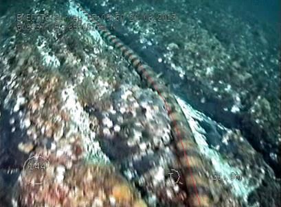
(therefore, maintaining the cable as close to parallel to the tide, where possible), and
    length of suspension (DNV RP F105 states that cable suspensions with a length less than
    30 times the diameter of the cable are not considered to be significant, i.e. at risk of
    strumming (the standard describes that length/diameter
2. Introduction
In March 2014, EMEC received funding from The Crown Estate to collate and review information
about the integrity of sub-sea cables installed at the EMEC wave and tidal test sites to help inform
on their performance in high energy environments. EMEC sub-contracted submarine cable
specialists Engineering Technology Applications Ltd (ETA) to carry out this review.

This report provides a summary of the review undertaken by ETA, and is intended for publication
to inform the marine renewable energy industry on factors affecting the integrity and performance
of sub-sea cabling, including conclusions from the review and an opinion on the status of the
cables in relation to age, tidal and wave environments. Pertinent recommendations for any further
work in this area are also made.

This report has been published by The Crown Estate as part of its enabling work to support
development of the Pentland Firth and Orkney waters wave and tidal projects. This work aims to
accelerate and de-risk the development process, looking at a range of key issues. Work is
selected, commissioned and steered by The Crown Estate in close discussion with the project
developers.

The European Marine Energy Centre Ltd (EMEC) was established in 2003 and is the first and
only facility of its kind in the world, providing developers of both wave and tidal energy converters
(technologies that generate electricity by harnessing the power of waves and tidal streams) with
purpose-built, United Kingdom Accreditation Service (UKAS) accredited open-sea performance
testing facilities. EMEC is located in the Orkney Islands off the north coast of mainland Scotland,
and has two principal grid-connected test sites, one for testing tidal energy converter devices and
the other for testing wave energy converter devices.

Whilst EMEC’s primary focus is the provision of services to industry for the rigorous testing of
marine energy convertor systems (MECS), it also participates in a variety of national and
international research projects aimed at providing the industry with essential information to
progress. This includes projects aimed at industry-related problems that can be tackled in some
generic capacity.

For more information on The Crown Estate’s work in wave and tidal energy, see
http://www.thecrownestate.co.uk/energy-and-infrastructure/wave-and-tidal/
or contact waveandtidal@thecrownestate.co.uk

For more information on EMEC’s work in wave and tidal energy, see www.emec.org.uk or
contact info@emec.org.uk

                                                                                     Page 6 of 47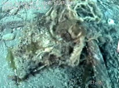
3. Background
Commercial wave and tidal energy generation sites in the Pentland Firth and Orkney waters
(PFOW) and around the UK are now entering initial planning phases, and supporting information
and data on how sub-sea cables perform in these high energy environments will be required by
both project developers and investors alike in order to progress successfully.
To date there has been very little published information on how sub-sea cables survive and
perform in high energy sites. The EMEC test sites currently have 12 sub-sea electrical cables
installed, for which a considerable amount of information is available from regular inspections and
testing. The oldest cables have been installed for approximately 10 years, and are installed at
varying angles to waves and tidal currents in high energy locations. EMEC has carried out
numerous routine remotely operated vehicle (ROV) surveys for structural integrity of the cables,
and also has data from comprehensive electrical testing throughout the period that the cables
have been installed. This information is expected to be of use to wave and tidal developers
entering the commercial planning phase in PFOW and elsewhere in the UK.
The key aim of the cable review project was to improve the industry’s understanding of how best
to specify and manage subsea cables for wave and tidal current projects, by investigating how
the cables installed at the EMEC test sites have been performing since installation.
3.1 Scope of Work
As mentioned above, the primary deliverable of the project is a report summarising the information
available from the EMEC site and providing analysis, conclusions, and recommendations for
future work based on this data. This summary report includes:
A short review of existing cable integrity information relating to the wave and tidal energy
sector and guidance available to developers
A summary of the information available from EMEC
Selection of which EMEC sub-sea cables were subjected to detailed review
Review of survey data for the selected EMEC cables, to include summary of:
o Serving wear
o Spans/tight bends
o Cable armour
o Anthropogenic interactions
o Cable movement
Review of cable performance data covering:
o Electrical – voltage/resistance tests
o Communications – Optical Time Domain Reflectometer (OTDR) tests
Consideration of factors affecting cable performance on selected cables, including:
o Seabed type
o Current speed and wave loadings
o Cable usage
o Cable to cable comparisons
Conclusions and recommendations for further work
Page 7 of 47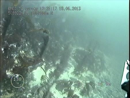
3.2 Methodology
To date, sub-sea cable installations in marine renewables areas have been guided by evidence
that is broadly anecdotal, and by the use of codes and standards centred on pipeline stability
(notably DNV RP F-109), the accuracy of which has never been tested in these specific
applications. As a primary goal then, this study sets out to assess the efficacy of current
techniques against the real world evidence available from the EMEC test sites.

In order to accomplish this, where possible the expected risks were set out independently and
prior to the assessment of the cable condition in order to ascertain any difference between
expected condition, and actual status. In comparing actual wear to expected risk, this study will
aim to identify if and where current models fall short and ascertain if any further variables affecting
the cable need to be accounted for. A key strength of the EMEC data is that the cables have
been installed at different times, often using varying techniques. By identifying cables in
comparable conditions that have been installed in different ways this study will attempt to expand
the list of variables to include installation parameters and thus provide conclusions and advice to
future developers.

The primary tools used to assess risk to the cable have been standard vortex induced vibration
calculations used to assess the risk to the cable from strumming, and DNV RP F-109 utilised to
assess cable stability (i.e. the likelihood of bodily movement).

Vortex induced vibration calculations are in general governed by three dimensionless groups: the
reduced velocity, the stability parameter and the Reynolds number. The principle variables
assessed are velocity of the current flow perpendicular to the cable and the natural frequency of
a suspension, each of which is affected by further variables. Current flow velocity perpendicular
to the cable is a function of the typical flow velocity (reduced when the cable is in greater water
depths) and angle of the cable to this flow. Natural frequency of a suspension depends on its
length, tension in the cable, and various cable parameters such as weight. The diameter of the
cable is also taken into consideration in reference to the interaction of the current with the cable.
Calculations show the necessary depth averaged current required to initiate strumming at different
multiples of the natural frequency. Cables calculated to strum at lower current velocities, often
reached at the site, were seen as being at higher risk. The level of risk of strumming calculated
was compared to actual observable damage on the survey footage (such damage was
categorised on a comparative scale in order to enhance comparison between suspensions).

The variables covered by DNV RP F-109 are similar to those for vortex induced vibration
calculations. This standard provides calculations for determining whether a cable is horizontally
or vertically stable in specific wave and current conditions. The calculations look at variables
including average conditions, depth of cable, the interaction of wave and tide, and cable size in
order to ascertain the forces experienced by the cable. Cable weight and seabed material are
then used to assess the likelihood of movement. Cables were assessed at varying points across
a range of conditions to determine conditions necessary for movement, and together with weather
data this was used to ascertain the risk to the cable. This again was compared to visible damage
at specific points, and along the length of the cable route.

It should be noted that there are some limitations with the data that may limit the scope of the
conclusions of this study. The primary limitation is on quantifying the level of wear to the cables;
while major risks (e.g. stability, strumming) can be quantified with ease, this is not the case for

                                                                                       Page 8 of 47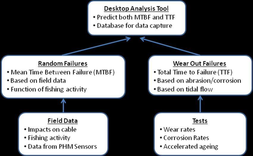
the results of these phenomena. Electrical test data yields results that are, in the most part, binary
(pass/fail) and as no cable failures have been reported to date this information is unlikely to yield
a detailed quantitative conclusion. Wear information instead comes from observed wear from
survey footage which is subject to interpretation and limited by how well areas have been captured
in the ROV surveys; information will therefore come from primarily qualitative sources. EMEC
does however have a wealth of survey footage, present and historical, which will allow sufficient
objectivity to be imparted by a comparative approach. Limitations will be identified where possible
and highlighted as recommendations for further study and investigation.

3.3 Brief Overview of State of the Art in Design for Reliability of Sub-sea Cables
The lifetime of a sub-sea cable is governed by the deterioration of the insulation material
properties under the influence of a combination of temperature, electric, chemical and mechanical
stresses. Over time, these factors decrease the dielectric strength of the cable, ultimately leading
to failure. Protecting the dielectric insulation layer is achieved using water blocking sheaths made
of polymeric or metal materials. These materials also protect the cable against mechanical
damage during cable transport and installation.

As detailed in Figure 1 below, the protection of the insulation layer is achieved using a number of
additional outer layers. These consist of the armour (usually made of steel wires) which provides
tension stability and mechanical protection particularly during installation and from external
aggression due to fishing gear and anchors. Double layer amour is sometimes used to provide
added protection. To protect the armour from corrosion the final outer layer of the cable consists
of hessian tapes, bitumen and yarn or polypropylene strings.

                            Figure 1: Construction of submarine power cable

                                                                                      Page 9 of 47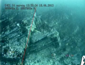
3.4 Other Work in this Field: Health Management System for Sub-sea Cables
Dr. David Flynn of Heriot-Watt University (HWU) has led an 18 month project funded by Scottish
and Southern Energy to investigate a first generation health management system. The team
developed a monitoring collar and desktop analysis tool to monitor sub-sea cables in-situ and to
predict the remaining useful life (RUL) of a cable. Utilising a 15 year historical data base, it was
identified that 70% of cable failure mechanisms were attributed to external/environmental factors.
The current state of the art in cable monitoring utilises either, or in combination, online electrical
condition monitoring and distributed temperature and strain (DTS) measurements via fibre optics.
These systems cannot monitor the failure modes associated with corrosion, abrasion and third
party impacts, e.g. shipping. Therefore, current commercial systems only support the monitoring
of 30% of the failure modes. This new health management system focuses on the majority share
of failure modes, as shown in Figure 2 below, but with a sensor agnostic architecture that enables
the integration of commercial monitoring systems.
Figure 2: Failure modes covered by the sub-sea cable Health Management System
Within Phase 1 (12months) of the project the team investigated a condition based health
monitoring system to monitor the degradation of sub-sea cables due to abrasive wear. This phase
of the project demonstrated:
Experimental technique to gather wear data for armour material
Model to predict cable movement based on defined tidal current
Model to predict wear in the amour over time
Embedded sensors that gather data on movement of the cable
Communications between the sensors and an embedded micro-controller containing the
wear model
Communications between the sensors and the shore
Page 10 of 47The above developments were undertaken to deliver a new monitoring technology that was retro-
fit-able to new and legacy sub-sea cable installations. Data on cable dynamics and the processes
of scour, abrasion and corrosion on the seabed at the time of development did not exist.
The reliability of sub-sea cables can be considered using the classical ‘bathtub’ curve which
demonstrates different failure rates against time in service (see Figure 3 below). Initially, there
may be a high rate of failure with a new sub-sea cable design due to poor design and
manufacturing defects. Sub-sea cable manufacturers aim to have manufacturing procedures in
place that would eliminate these failures. The second phase as known represents random
failures, which for sub-sea cables would be due to unforeseen incidents such as third party
impacts due to fishing activity. The final phase is wear-out, which for sub-sea cables would be
failures due to abrasion and corrosion.
Figure 3: Bathtub curve for reliability
A brief review of the available literature demonstrates that sub-sea cable manufacturers undertake
a number of tests to qualify a cable before shipping to customers. These tests are detailed by
Thomas Worzyk in the book Submarine Cables (pages 136-148) where accepted standards
(International Electrotechnical Commission (IEC), etc) are used. These tests focus mostly on
electrical and thermal behaviour of the cable. The main standard for mechanical testing is
documented in CIGRE Electra 171 which is used to test torsional and bending stresses in cables,
particularly to assess their strength during installation.
Cable abrasion and corrosion rate measurements are detailed in IEC 60299 standard. In the
abrasion test, a cable is measured through a mechanical rug test using a steel angle dragged
horizontally along the cable. This test was designed for the cable in the laying operation; hence it
does not reflect the abrasion behaviour of the cable when it moves along the seabed in the
working environment.
Hence in assessing the overall reliability/life of a cable design before deployment, a number of
factors such as those detailed above need to be considered. A desktop tool to assess probable
lifetime and risks of failure in a specified sea environment will need to consider all of these factors.
At present, HWU has designed and developed a first generation of such a tool (see Figure 4
below). To HWU’s knowledge there is currently no other analysis tool available that can predict
Page 11 of 47the expected lifetime of a sub-sea cable when subjected to defined seabed conditions and tidal
flows. During blind testing this system predicted the accuracy of cable RUL within one month.
Future work will focus on expanding the historical database, integrating additional data from
commercial monitoring systems, scaling up the monitoring hardware, and validating the system
against a larger case study set.
Figure 4: Sub-sea cable lifetime prediction tool developed by Heriot-Watt University
The tool uses knowledge from historical failures, rates of material degradation, modelling of cable
displacement and in-situ cable monitoring enable a prediction of the RUL of a given cable zone.
Different cable types in different environments can instantly be compared to enable the optimal
planning of cable type and route.
Page 12 of 474. Cables in High Energy Environments: Current Knowledge
Submarine cables are typically designed with a design life of 25 years or more, but are not
normally subjected to strong tidal currents or the aggressive conditions associated with wave and
tidal energy sites.
In general, power cable failure data is not readily available but the International Council on Large
Electric Systems (CIGRE), an International Association of large utilities, have attempted to collate
data reported by cable owners and manufactures. It is thought that this data will have limitations
as not all faults are reported. The key points of the CIGRE study can be summarised as follows:
Of all cable faults reported, around 50% were due to fishing and anchoring, and risks at
the EMEC site are low all the way along the cable route
Average failure rate for all types of submarine power cables are 0.1114 faults/100 km/year
The major part of these failures occurred after nearly 10 years and more in operation
A reduction in fault rates have been observed from a previous CIGRE study (this is
attributed to most new cables being buried to a depth of at least 0.5m and improved survey
leading to better route design)
This, and other similar reports, constitutes the extent of formalised data available on power cable
faults; none of this is directly applicable to wave and tidal energy test sites. At present, all context
specific data is purely anecdotal and comes from a very limited collection of circumstances.
For surface laid power cables around Scotland, where aggressive conditions are common, a
service life of around 18 to 24 years is expected. In areas where cables are laid perpendicular to
strong currents in rocky conditions however, these have been known to fail in much shorter
timescales. Anecdotal evidence suggests that in some high tidal areas around Scotland where
cables are laid on the surface and perpendicular to the tide they have failed 6 to 8 years after
installation. It is suspected that these cables are not only laid perpendicular to the tide but also
under relatively high residual tension, leading to large suspensions which are the cause of failure
(due to vortex induced vibration). No formal figures have been released for these cables.
Further evidence for significantly reduced service life can be taken from the experiences with the
submarine cables laid between Rockport, Maine and the islands of North Haven and Vinalhaven
(which has been dubbed the world’s worst submarine cable). Here, the 17km of cables had been
laid over a number of areas of rugged bottom, the worst of which was a 15m high rock outcrop
with near vertical walls on both sides (after 13 years in service, the first fault occurred in the area
of this outcrop). It is worth noting that this cable was single armoured.
It is difficult to draw ultimate conclusions from this anecdotal data, and thus predictions relating to
service life of cables can rarely be made as the conditions of lay can only be speculated upon. It
can only be said that it appears that service life will be reduced. In this regard, with extensive
survey information, and site specific current information, the data relating to EMEC sub-sea
cables could provide a significant improvement in predicting sub-sea cable life.
Page 13 of 475. Cable and Site Information
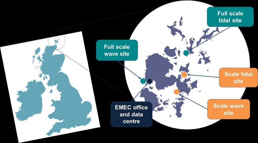
EMEC operates two grid-connected full scale test sites, one at Billia Croo on the western edge of
Orkney Mainland (wave energy test site), and the other at the Fall of Warness to the west of the
island of Eday (tidal energy test site). In addition to these grid-connected test sites, EMEC also
operates two ‘scale’ test sites to allow developers to test prototype scale versions of their
technologies and deployment techniques in less challenging conditions. Figure 5 below shows
the locations of the EMEC test sites.
Figure 5: Graphic showing location of EMEC test sites
5.1 Wave Energy Test Site
The EMEC wave energy test site was constructed in 2003 with the installation of four sub-sea
cables, and is ideally placed at Billia Croo on the western edge of the Orkney Mainland. Subjected
to the powerful forces of the North Atlantic Ocean, it is an area with one of the highest wave
energy potentials in Europe, with an average significant wave height of 2m – 3m, but reaching
extremes of up to 17m (the highest wave recorded by EMEC so far). An additional berth was
established in 2010, and the site now consists of five cabled test berths in up to 70m water depth
(four at 50m, one at approximately 70m), located approximately 2km offshore and 0.5km apart.
In addition to this, a near-shore berth is situated closer to the substation for shallow water projects.
Figure 6 below shows the extent of the EMEC wave energy test site at Billia Croo (dashed lines)
together with the approximate route of the five sub-sea cables (red lines).
Page 14 of 47The EMEC wave energy test site is characterised by dramatic seabed topography, and with the
cables laid in relatively high tensions (estimated 1.5-2t) across this they hang mostly in freespan,
in some areas touching down briefly every 20-30m.
The current profile at the wave energy test site is also significantly different. As opposed to a
single directional tidal current, the water flow is influenced by the wave activity at the site. Tidal
flow itself is indicated to be relatively low, with a large component of the current coming from the
waves. Overall current direction is therefore highly variable and must always be assumed to act
in worst case at 90o to the cable (this should be roughly true of tide-only currents for W2 and W3
as the tidal direction is North-South, and the cables are laid East-West). Current velocity is also
highly variable at the wave energy test site, as it is dependent on wave height.
5
1
2
3
4
Figure 6: Graphic showing area of the EMEC wave energy test site at Billia Croo, Orkney
5.2 Tidal Energy Test Site
The EMEC tidal energy test site at the Fall of Warness is situated just west of the island of Eday,
lying in a narrow channel between the Westray Firth and Stronsay Firth. As tides flow from the
North Atlantic Ocean to the North Sea, they quicken as they are funnelled through Orkney's
northern islands. The site was chosen for its high velocity marine currents which reach almost
4m/sec (7.8 knots) at peak spring tides.
The first sub-sea cables were installed at the site during 2006, at depths ranging from 12m to 50m
in an area 2km across and approximately 4km in length. The site now accommodates eight
cabled test berths (the cable nearest to the shore, cable 8, was installed by an EMEC client, and
is not included in this study). Each 11kv sub-sea cable extends to the middle of the tidal stream
from EMEC's substation at Caldale in Eday, from where it is routed to the individual test berths.
Figure 7 below shows the extent of the EMEC tidal energy test site at Fall of Warness (dashed
lines) together with the approximate route of the eight sub-sea cables (red lines).
Page 15 of 47At the tidal test site, the 60% depth averaged current at the site reaches speeds approaching 4
m/s on the spring tide, and decays with depth according to the 1/7 power law. Typical day to day
peak current is around 2.6 m/s. Current flows on the line between 330/340o and 150/160o
(accounting for a minor difference between flood and ebb). This is affected by some seabed
features, and in particular Seal Skerry in the area of T4, but it was largely assumed to be
consistent for this study.
4
7
6
5
8
1
2
3
Figure 7: Graphic showing area of the EMEC tidal energy test site at Fall of Warness, Orkney
5.3 Cable Details
The cables at the wave energy test site at Billia Croo and the tidal energy test site at the Fall of
Warness are broadly similar, with an 11kv cable running from an onshore substation out to each
open-sea berth.
The cables are wet-type composite cables consisting of three Ethylene Propylene Rubber (EPR)
-insulated stranded copper power cores designed for alternating current; three 2.5mm2 copper
signal/pilot trip cables; and a 12-core single-mode fibre-optic bundle. Each cable is then
armoured with two layers of galvanised steel wire. Cables were provided by AEI Cables Ltd (wave
energy test site cables) & Pirelli/Prysmian Group UK (tidal energy test site cables).
In 2010, a UK Department of Energy and Climate Change (DECC) funded project enabled EMEC
to increase the berth capacity by installing new cables. These cables, built by Draka in Norway,
are of a similar specification to the cables described above, but are cross-linkable polyethylene
compounds (XLPE) -insulated and include an additional 4 core 4mm2 auxiliary power cable. Two
additional cables were installed at the tidal energy test site and one at the wave energy test site,
using a total of 12km of newly procured cable.
Page 16 of 47The cables were laid as standard sub-sea cables on the sea bed. As the cables approached the
shore, in 15m of water, ductile iron cable protectors were attached. At the low water spring tide
mark, each passes into a trench dug 1.2m into the seabed and beach. On shore, the cables are
fed into a manhole and then into an electricity substation. At the seaward end, each cable, when
not occupied by a developer, is terminated using a specially designed end-cap.
Table 1 and Table 2 below provide a summary of the sub-sea cables installed at EMEC to date,
showing intervention history and data available for each cable.
Page 17 of 47Fall of Warness Tidal Energy Test Site
Cable 1 Cable 2 Cable 3 Cable 4 Cable 5 Cable 6 Cable 7
1. Cable type
Manufacturer Pirelli Pirelli Pirelli Pirelli Pirelli Draka Draka
DWA fully DWA fully DWA fully DWA fully DWA fully DWA semi- DWA semi-
Construction
flooded flooded flooded flooded flooded flooded flooded
Insulation EPR EPR EPR EPR EPR XLPE XLPE
Csa Cu 120mm2 Cu 120mm2 Cu 120mm2 Cu 120mm2 Cu 120mm2 Cu 120mm2 Cu 120mm2
2. Date of installation
Aug-Oct 2005:
Aug-Oct 2005:
Recovery gear 2010: Laid with
Two known Aug-Oct 2005 Aug-Oct 2005 Aug-Oct 2005 2010: Note 4.
lost, cable J+S end fitted.
kinks.
tangle at end
3. Outline of interventions and use
July 2008: June 2008: July 2008: 2007: cable 2006: Aug 2010: Cable Sep 2013: Cable
Cable end Cable end Damage due to Lifted, relocated Unsuccessful lifted, moved, lifted, moved,
disturbed as moved laterally barge run-off. to developer’s attempts to connected to spliced to client
result of barge to allow device, pulled in recover cable, client sub-sea cable
run-off. foundation through J-tube. thought to have structure. (Note management
works. Several cable had limited 5) system.
handling contact with
operations cable.
within this
scope, see note
3.
July 2010: July 2008: Aug 2009: 2007 - present: Sept 2010: Oct 2010: Cable
Cable lifted, Damage due to Damage due to Cable energised Cable lifted, disconnected
tested, cut back barge run-off. anchor drag at 11kV unknown length from sub-sea
approx. 900m to during removed, J+S structure
remove kinks, operations. test end fitted.
tested again.
Aug 2010: Jan 2010. Oct 2010: Cable 20-Sep to 11- Apr 2011: Cable
Cable lifted, kink Approx. 180m lifted, 650m Oct-10: Cable reconnected to
removed, 1km damaged cable damaged cable energised at sub-sea
repair length removed, 200m removed, 600m 11kV structure
spliced to end. Developer’s 8kV repair length
Page 18 of 47umbilical spliced fitted c/w J+S
on. test end, laid
temporarily on
seabed,
retrieved and re-
laid on desired
route 2 weeks
later.
Oct 2011: Cable August 2010 - Oct 2010 - 17- Nov 2011: Cable
lifted, short present: Cable Jul-13: Cable disconnected
client cable in service at energised at from sub-sea
(100m of Draka 6.6kV 11kV (J+S test structure
120mm2) end)
spliced on. Kink
thrown in repair
length.
Dec 2011:
Nacelle
connection (may
have disturbed
the splice)
Dec 2011 - Jan
2013: In
service, variable
voltage and
frequency up to
6.6kV.
Jan 2013:
Nacelle
removed (may
have disturbed
the splice).
Aug 2013: Cable
lifted, cut back
beyond kink,
new repair
length added.
Page 19 of 47Aug 2013:
Nacelle
reconnected.
Aug 2013 –
present: In
service, variable
voltage and
frequency up to
6.6kV.
4. Electrical test data available
2005 - 2010: 2005 - 2010: 2005 - 2010: 2005 - 2007: 2005 - 2010: 2005 - 2010: July 2010: Tests
note 0 Note 0 Note 0 Note 0 Note 0 Note 0 as note 2
July 2010: 2008: Various 2008: Various 2007: IR and dc Sept 2010: Test July 2010: Post- Feb 2012: Tests
Tests as note 1 tests associated tests associated pressure test as per note 2 installation tests as note 2, cable
with cable ops with cable ops prior to to 5kV unterminated
and damage, and damage, energisation onshore.
mostly optical. mostly optical.
Aug 2010: Jan 2010: Client Oct 2010: Test Feb 2012: 5kV Aug 2010: Client Mar 2013: Tests
Tests as note 1. tests including as per note 2 IR test handover tests as note 2 after
VLF to 12.7kV to 5kV onshore
termination.
Oct 2011: Tests Apr 2013: 5kV July 2013: Tests
as note 2 at IR test as note 2 at
handover to handover to
client. client
5. Resource data available
Wave Height Wave Height Wave Height Wave Height Wave Height Wave Height Wave Height
every 100m(M) every 100m(M) every 100m(M) every 100m(M) every 100m(M) every 100m(M) every 100m(M)
Period every Period every Period every Period every Period every Period every Period every
100m(M) 100m(M) 100m(M) 100m(M) 100m(M) 100m(M) 100m(M)
Direction every Direction every Direction every Direction every Direction every Direction every Direction every
100m (M) 100m (M) 100m (M) 100m (M) 100m (M) 100m (M) 100m (M)
Current speed Current speed Current speed Current speed Current speed Current speed Current speed
every 100m (M) every 100m (M) every 100m (M) every 100m (M) every 100m (M) every 100m (M) every 100m (M)
Page 20 of 47Current direction Current direction Current direction Current direction Current direction Current direction Current direction
every 100m (M) every 100m (M) every 100m (M) every 100m (M) every 100m (M) every 100m (M) every 100m (M)
ADCP (at ADCP (at ADCP (at ADCP (at ADCP (at ADCP (at ADCP (at
specific location) specific location) specific location) specific location) specific location) specific location) specific location)
Waverider buoy Waverider buoy Waverider buoy Waverider buoy Waverider buoy Waverider buoy Waverider buoy
(at specific (at specific (at specific (at specific (at specific (at specific (at specific
location) location) location) location) location) location) location)
Bathymetry at Bathymetry at Bathymetry at Bathymetry at Bathymetry at Bathymetry at Bathymetry at
2m resolution 2m resolution 2m resolution 2m resolution 2m resolution 2m resolution 2m resolution
6. ROV data available
2006 offshore 2006 offshore 2006 offshore 2006 offshore 2006 offshore 2010 offshore 2010 offshore
2009 offshore 2008 offshore 2008 offshore 2007 offshore 2008 offshore 2012 inshore 2012 offshore
2010 offshore 2009 offshore 2009 offshore 2008 offshore 2009 offshore 2013 offshore 2012 inshore
2010 inshore 2010 inshore 2010 inshore 2009 offshore 2010 inshore 2013 offshore
2012 inshore 2011 offshore 2010 offshore 2010 inshore 2010 offshore
2013 offshore 2011 inshore 2011 offshore 2010 offshore 2012 offshore
2013 offshore 2013 offshore 2011 offshore 2013 offshore
2011 inshore
2013 offshore
7. Cable Routes
SW from SW from SW from SW from SW from SW from SW from
substation substation substation substation substation substation substation
S from 30m S from 30m S from 30m Roughly follows S from 30m SW to beyond SW to beyond
contour contour contour 20m con contour 30m con 30m con
SW from 50m west of turbine South after 30m South after 30m
contour con con
east back to
turbine
Complex route Complex route Complex route
offshore offshore offshore
Notes:
Note 0: Cables originally laid with Pirelli pulling head, not able to accept high voltage test.
Note 1: Tests include continuity, IR at 5kV, VLF at 12.7kV and partial discharge. Also OTDR.
Note 2: Tests include continuity, IR at 5kV and VLF at 12.7kV. Also OTDR.
Note 3: First move introduced kink.
Page 21 of 47Kink removed, tested, reported.
Second move to platform, then incremental pull-in.
Cable easing works.
Note 4: Cable 6 laid with client's own end fitment. Client advised 5kV max test voltage.
Note 5: Client did not use an umbilical. Some issues with management of slack cable.
Table 1: Summary of sub-sea cables installed at the EMEC tidal energy test site, Fall of Warness, Orkney
Page 22 of 47Billia Croo Wave Energy Test Site
Cable 1 Cable 2 Cable 3 Croo Cable 4 Cable 5
1. Cable type
Manufacturer: AEI AEI AEI AEI Draka
Construction DWA fully flooded DWA fully flooded DWA fully flooded DWA fully flooded DWA semi-flooded
Insulation EPR EPR EPR EPR XLPE
Csa Cu 50mm2 Cu 50mm2 Cu 50mm2 Cu 50mm2 Cu 120mm2
2. Date of installation
2003 2003 2003 2003 2010
3. Outline of interventions and use
2004: First device trials 2006: Cable lifted to fit 2006: Cable lifted to fit 2006: Cable lifted to fit June 2012: Cable
at 11kV. Cable lifted to Henley pulling head Henley pulling head Henley pulling head handover to client.
make bolted connection (Note 0) (Note 0) (Note 0)
to client’s umbilical
within oil-filled junction
box.
2006: Cable lifted to fit 2010: Cable lifted, J+S Jan 2010: Cable lifted for 2010: Cable lifted, J+S July 2012: Cable lifted
Henley pulling head test end fitted testing. Recapped with test end fitted for splicing of client
(Note 0) modified Henley end. umbilical.
2006: Cable lifted to 2011-12: Several cable Sep 12: Client umbilical
splice on client umbilical. operations to achieve a parted in severe
successful splice of new weather.
umbilical
2007: Device trials at 2012- present: Device June 2013: Cable lifted,
6.6kV trials at 6.6kV umbilical replaced.
2010: Cable lifted to 2014: Cable in use.
splice new umbilical
2010 – present: Device
trials at 6.6kV
4. Electrical test data available
2006: Various IR tests at 2010: Tests as Note 1 2010: Tests as Note 2 2010: Tests as Note 1 June 2012: Tests as
splicing note 2 prior to handover
to client
Page 23 of 472007: Various IR tests 2011-12: Tests as Note 2010 – present: A small 2010 – present: A small 2012 – present: A small
2 at splicing number of IR tests at number of IR tests at number of IR tests at
1kV. 5kV. 5kV.
2010: Tests as Note 2 at
splicing
2010 - 2013: Continuity 2012-present: Continuity
and IR data as Note 3 and IR data as Note 3
from 15 device from 12 device
deployment cycles deployment cycles
5. Resource data available
Wave Height every Wave Height every Wave Height every Wave Height every Wave Height every
100m(M) 100m(M) 100m(M) 100m(M) 100m(M)
Period every 100m(M) Period every 100m(M) Period every 100m(M) Period every 100m(M) Period every 100m(M)
Direction every 100m Direction every 100m Direction every 100m Direction every 100m Direction every 100m
(M) (M) (M) (M) (M)
Current speed every Current speed every Current speed every Current speed every Current speed every
100m (M) 100m (M) 100m (M) 100m (M) 100m (M)
Current direction every Current direction every Current direction every Current direction every Current direction every
100m (M) 100m (M) 100m (M) 100m (M) 100m (M)
ADCP (at specific ADCP (at specific ADCP (at specific ADCP (at specific ADCP (at specific
location) location) location) location) location)
Waverider buoy (at Waverider buoy (at Waverider buoy (at Waverider buoy (at Waverider buoy (at
specific location) specific location) specific location) specific location) specific location)
Definition of Surf zone Definition of Surf zone Definition of Surf zone Definition of Surf zone Definition of Surf zone
Bathymetry at 2m Bathymetry at 2m Bathymetry at 2m Bathymetry at 2m Bathymetry at 2m
resolution resolution resolution resolution resolution
6. ROV data available
2006 inshore 2006 offshore 2006 offshore 2006 offshore 2010 offshore
2008 inshore 2008 inshore 2008 inshore 2008 inshore 2011 inshore
2008 offshore 2008 offshore 2008 offshore 2007 offshore 2013 offshore
2009 offshore 2009 inshore 2009 inshore 2008 offshore
2011 offshore 2009 offshore 2009 offshore 2009 inshore
2013 offshore 2010 offshore 2011 inshore 2009 offshore
2011 offshore 2011 offshore 2010 offshore
2011 inshore 2013 offshore 2011 inshore
Page 24 of 472013 offshore 2013 offshore
7. Cable Routes
West from substation West from substation West from substation West from substation West from substation
NW to offshore after NW to offshore after W to offshore after gully SW to offshore after gully NW to offshore after
gully gully gully
Notes:
Note 0 HV cores cut and capped but not prepared for electrical testing. Tests therefore not possible with henley end.
Note 1 Tests include continuity, IR at 5kV, VLF at 12.7kV and partial discharge. Also OTDR.
Note 2 Tests include continuity, IR at 5kV and VLF at 12.7kV. Also OTDR.
Note 3 tests at connection include continuity through star-wound transformer at device, and 5kV IR all phases together
Note 4 tests at disconnection include 5kV IR each phase (one up, two down)
Table 2: Summary of sub-sea cables installed at the EMEC wave energy test site, Billia Croo, Orkney
Page 25 of 475.4 Summary of General Cable Condition
The following sections provide a summary of the 12 sub-sea cables installed by EMEC (seven at
the tidal energy test site and five at the wave energy test site).
5.4.1 Fall of Warness Cable 1 (T1)
The most recent ROV survey of this cable was carried out in October 2012. The majority of wear
identified in the most recent ROV survey of T1 is related to installation issues. A very tight kink
is observed in the cable at the offshore end. Nearer the device gravity base there is also a steel
bend-restrictor quadrant with a 360 loop of cable around it. The kink was removed in August
2013. Adjacent to this is the terminal J+S box, which at time of survey is spliced onto a jumper
cable connected to the turbine. This was disconnected in January 2013, and reconnected in
August 2013. The cable is currently energised at variable voltage up to 6kV.
Apparent risks to this cable are mainly from anthropogenic interactions including limited fishing
activity and an additional cable crossing which has been protected with grout bags. The condition
of the cable appears generally good with no significant areas of damage observed in the 2012
survey.
5.4.2 Fall of Warness Cable 2 (T2)
The most recent ROV survey of this cable was carried out in June 2013. This cable is generally
in good condition, as observed from ROV surveys carried out in in 2011 and 2013. There are two
significant areas of wear, one due to a cable bight close to the device tripod which has caused
serving wear, and the second around 270m from the device tripod, seemingly due to abrasion on
the rocky seabed in the main tidal flow. Inshore, the cable is laid over sandy shingle, and has
partial burial as well as additional armour.
Apparent risks are largely limited to the rocky seabed in the main tidal flow, and little to no
anthropogenic interactions can be observed. The cable does not have any significant rock
contacts, or free-spans of any notable scale.
5.4.3 Fall of Warness Cable 3 (T3)
The most recent ROV survey of this cable was carried out in June 2013. This cable is observed
to be in good condition with little damage other than minor serving deterioration described by the
surveys “as normal loosening of serving in a few places”. The 2011 survey reported one 2m
section in which serving separation has caused the armour wires to become exposed; this is not
reported on the 2013 survey. The 2013 survey notes that no movement or additional wear is
evident between 2011 and 2013.
A number of cable crossings with the Environmental Monitoring Pod cable constitute the only
reported anthropogenic risk to the cable, and these have remained stable to the date of the most
recent survey (June 2013). Seabed conditions are similar to those of T2 and the cables run along
similar routes.
Page 26 of 475.4.4 Fall of Warness Cable 4 (T4)
The most recent ROV survey of this cable was carried out in June 2013. This cable sits on some
of the most hostile rocky terrain within the site, skirting the southern end of the reef that extends
south of Seal Skerry. There are considerable freespans over gullies and tight bends around sharp
rock edges with no split pipe protection. There is also evidence of fishing activity in the area with
a couple of creels and associated rope wound around the cable. Inshore towards the substation,
the 2 newest cables on the site, T6 & T7 cross over T4, with concrete mattress protection.
There are many areas of visible wear on T4 with serving detached and areas of armour wire
visible. T4 has been energised since 2007 at approximately 11kV. 300m of the cable was moved
in order to facilitate connection operations, and following this move, remedial work was conducted
to minimise ‘at risk’ suspensions. Much of the serving wear is thought to have occurred during
cable movement, and little deterioration has been observed since. To date it appears that while
there are areas of wear, freespans, rock contacts, and fishing activity, cable performance has not
been affected.
5.4.5 Fall of Warness Cable 5 (T5)
The most recent ROV survey of this cable was carried out in February 2012. This cable is
regarded as being in very good condition. Recent surveys note an absence of any armour
damage, no significant freespans, and only a limited number of point contacts. This cable has
not yet been energised.
There are a number of creel ropes crossing the cable, as well a crossing from cable 8 (the EMEC
client-owned cable). No damage can be seen from these interactions.
5.4.6 Fall of Warness Cable 6 (T6)
The most recent ROV survey of this cable was carried out in June 2013. This cable was installed
as part of the expansion of the EMEC facility in 2010. It lies in close proximity to T4 (which it
crosses) and to T7 which was laid at the same time. Post-lay ROV survey observed that the cable
was laid at relatively high tensions towards the inshore, compared to T7. In contrast, offshore the
cable snakes across the seabed, laid with very little residual tension.
This cable appears to be in good condition. Offshore the cable is laid over rocky edges with many
short freespans whereas inshore the cable is well supported in shingly sand. There is a location
where the cable is hard up against a small vertical rock face, and another where it appears to be
laid in tension around a rocky lump. There is only slight evidence of loose serving or surface
attrition to the cable on the entire length.
Page 27 of 475.4.7 Fall of Warness Cable 7 (T7)
The most recent ROV survey of this cable was carried out in June 2013. This cable is the second
of the cables installed at the tidal energy test site in 2010. It lies in close proximity to T4 (which it
crosses) and to T6 which was laid at the same time. Post-lay ROV survey observed that the cable
was laid at relatively low tensions, compared to T6.
This cable was the subject of a separate independent survey in 2012 to investigate an anomaly
in TDR testing. This survey highlighted many areas of wear and abrasion which was corroborated
by the ROV survey carried out in June 2013. While freespans and point contacts are limited (as
are anthropogenic interactions) there are areas where cable movement has clearly resulted in
significant serving wear on the rocky seabed. No breaks in the armour wires were observed
during the survey.
5.4.8 Billia Croo Cable 1 (W1)
The most recent ROV survey of this cable was carried out in July 2013. This cable crosses some
dramatic seabed geography close inshore consisting of rock shelves, geos and small cliff edges.
This results in some considerable freespans and potential areas of stress on the cable where it is
forced to turn over rocky edges. Most of the split pipe protection is obscured in the ROV surveys
due to kelp fronds inshore. As the cable enters deeper water, it enters areas of significant burial
in sand and shingle waves.
There are several areas in which the serving has worn away and the armour is exposed, and
indications suggest that at least one of these is possibly due to anthropogenic interactions. Split
pipe protection also appears to have separated from the cable in areas where it is needed, such
as a contact with cable W2 (it is believed that most of this occurred during installation operations).
5.4.9 Billia Croo Cable 2 (W2)
The most recent ROV survey of this cable was carried out in July 2013. As with all the wave site
cables, W2 passes through a dramatic area of seabed geography towards the landfall, resulting
in many unarmoured sharp point contacts and long freespans. While there is serving wear leaving
steel wire armour exposed, given the age of the cable the serving remains remarkably intact. No
damage to the steel wire armour strands was noted. There is also evidence of a phenomena that
was noted in 2011 where there appears to be staining of the rock around areas of serving wear.
It is not clear whether this is caused by the loose serving scrubbing the rock clean, or by
substances (such as bitumen) being removed from the cable.
There is evidence of considerable anthropogenic interaction with W2 with several chains and
ropes lying in close contact with the cable. Serving wear though can most likely be attributed to
cable movement and seabed conditions.
5.4.10 Billia Croo Cable (W3)
The most recent ROV survey of this cable was carried out in July 2013. This cable runs through
some dramatic seabed geography towards the landfall. There is evidence of serving deterioration,
possibly due to slight cable movement around the freespans. There is some evidence of
discolouration of rocks around the cable as with the other wave cables.
Page 28 of 47The loose serving has exposed the wire armour in many places, and there are many locations
where the cable is clearly stressed as it passes over sharp rock edges with no split pipe protection.
There are a number of clear anthropogenic interactions with the cable but as with W2 the serving
wear appears to be largely due to cable movement.
5.4.11 Billia Croo Cable 4 (W4)
The most recent ROV survey of this cable was carried out in December 2012. Inshore of
approximately 30m depth, this cable is laid across dramatic rock slabs with many geos and vertical
edges, leading to the cable lying mostly in freespan for the first 1000m offshore with many point
contacts on rock. Serving wear is visible, with evidence of apparent colouring of the surrounding
rock.
There is a particularly long (90m) section of freespan inshore where the cable is suspended
between a few rock edges. There is evidence of cable movement (and possible strumming) in
this region (rock edges worn fresh & bright where the cable is in contact). Also noted was fresh
broken rock under the cable though this could be due to the natural erosion process caused by
storm waves rather than attrition from cable movement.
Offshore this cable is stabilised in sand.
5.4.12 Billia Croo Cable 5 (W5)
The most recent ROV survey of this cable was carried out in December 2012. This cable is well
armoured inshore from the beach out to 20m depth, and as with all the other wave site cables,
W5 passes over some very dramatic underwater geography, with numerous short but high
freespans, vertical and horizontal rock edges.
There is an area of (possibly dynamic) sand waves further offshore, where the cable is alternately
in total burial and short freespan. Offshore of that, W5 enters total burial in sand for the majority
of its length, emerging in the vicinity of the J+S termination box. This cable has a flexible jumper
cable leading from the J+S box to a device under test.
No armour damage and very little serving wear was noted throughout the length of W5.
Page 29 of 475.5 Cable Selection
After initial review of the data available for all cables, the following cables were selected for more
detailed analysis/review:
Tidal 4 (T4)
Tidal 6 (T6)
Tidal 7 (T7)
Wave 2 (W2)
Wave 3 (W3)
T4, T6, and T7 are all laid across a similar area of the site in perhaps the most hostile waters.
The cables are in close proximity, are laid at varying angles to the tidal flow, and are laid in varying
tensions. Cable T4 has been the subject of remedial cable work. Due to the surrounding features
the cables have excellent prospects for comparison, as the impact of different variables can be
observed within roughly the same conditions.
With regards to the cables at the wave energy test site, conditions are considered fairly similar
across the site. Cables W2 and W3 were selected for their close proximity to each other, and the
large number of features drawn out from the ROV survey reports. There is also a noticeable
difference in the levels of wear on each of these cables.
Page 30 of 47You can also read