Dual-comb ranging with frequency combs from single cavity free-running laser oscillators
←
→
Page content transcription
If your browser does not render page correctly, please read the page content below
Research Article                                       Vol. 29, No. 16 / 2 August 2021 / Optics Express 24910

Dual-comb ranging with frequency combs from
single cavity free-running laser oscillators
J ACOB N ÜRNBERG , B ENJAMIN W ILLENBERG ,                                        C HRISTOPHER R.
P HILLIPS , * AND U RSULA K ELLER
Department of Physics, Institute for Quantum Electronics, ETH Zürich, 8093 Zürich, Switzerland
* cphillips@phys.ethz.ch

Abstract: Laser ranging (LIDAR) with dual optical frequency combs enables high-resolution
distance measurements over long ranges with fast update rates. However, the high complexity
of stabilized dual optical frequency comb systems makes it challenging to use this technique in
industrial applications. To address this issue, here we demonstrate laser ranging directly from
the output of both a free-running dual-comb diode-pumped semiconductor and solid-state laser
oscillator. Dual-comb operation from a single cavity is achieved via polarization duplexing with
intracavity birefringent crystals. We perform ranging experiments with two implementations of
this scheme: a modelocked integrated external cavity surface-emitting laser (MIXSEL) and a
Yb:CaF2 solid-state laser. For these proof of principle demonstrations, we measure the distance
to a moving mirror mounted on a home-made shaker. The MIXSEL laser has a repetition rate of
2.736 GHz and a repetition rate difference of 52 kHz, and yields a measurement resolution of
1.36 µm. The Yb:CaF2 laser has a repetition rate of 137 MHz and a repetition rate difference of
952 Hz, and yields a measurement resolution of 0.55 µm. In both cases the resolution is inferred
by a parallel measurement with a HeNe interferometer. These results represent the first laser
ranging with free-running dual-comb solid-state oscillators. With further optimization, resolution
well below 1 µm and range well above 1 km are expected with this technique.

© 2021 Optical Society of America under the terms of the OSA Open Access Publishing Agreement

1.    Introduction
Modern day technological advancements demand solutions to fast distance measurements with
high precision and range. Any distance measurement is quantified by precision and accuracy,
ambiguity range and by the update rate. Laser based ranging has proven to be fast and reliable
even for more sophisticated ranging challenges in a wide variety of fields including object
detection and recognition.
   Interferometric laser ranging systems, such as a Michelson interferometer, determine the phase
shift of a signal after traversing an unknown distance. Although they provide sub-wavelength
resolution, these systems have an extremely short ambiguity range on the scale of the wavelength
itself. Multiwavelength interferometers achieve increased but still limited ambiguity ranges
through the generation of a synthetic longer wavelength [1–4].
   The limited range of traditional interferometric techniques can be overcome by light detection
and ranging (LIDAR), where the optical delay of a pulsed or modulated waveform is used to infer
distance. The two dominant approaches, namely time of flight LIDAR and frequency-modulated
continuous-wave LIDAR, have shown sub-millimeter precision over large ambiguity ranges
[5–7]. Using frequency combs, various approaches have shown long ambiguity ranges with high
precision and fast scanning speeds by leveraging simultaneous heterodyne or superheterodyne
detection [6,8–10].
   In LIDAR with dual optical frequency combs (dual-combs), ranging is achieved by exploiting
the time scaling within the beatnote of two mutually coherent frequency combs in a similar manner
to equivalent time sampling [11,12]. Dual-comb LIDAR has the advantage of simultaneously
offering long range and high resolution without requiring any moving mechanical parts to scan

#428051                                                                        https://doi.org/10.1364/OE.428051
Journal © 2021             Received 15 Apr 2021; revised 30 Jun 2021; accepted 13 Jul 2021; published 21 Jul 2021
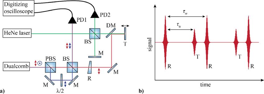
Research Article                                 Vol. 29, No. 16 / 2 August 2021 / Optics Express 24911

delay. The first demonstration in 2009 was based on two stabilized fiber frequency combs [13].
Since then, similar measurements have been demonstrated with free running fiber combs [14],
including single-cavity fiber based systems [15–17], and microresonator based frequency combs
[18,19].
   Here, we present dual-comb LIDAR experiments using two types of free-running dual-comb
laser oscillators: a modelocked integrated external cavity surface-emitting laser (MIXSEL) [20],
and a solid-state laser. The lasers themselves were presented previously [21,22]; the MIXSEL
was applied to dual-comb spectroscopy, while the solid-state laser was applied to pump-probe
sampling. In both of these lasers, we use polarization duplexing with intracavity birefringent
crystals to generate two frequency combs from a single laser cavity [23]. A small and adjustable
repetition rate difference is obtained by inserting a pair of 45°-cut birefringent crystals into the
cavity. We perform ranging experiments with the dual-comb MIXSEL and compare the results
to the dual-comb Yb:CaF2 laser. With the MIXSEL, we sample at an update rate of 52 kHz with
a resolution of 1.36 µm. The Yb:CaF2 laser achieves an even higher resolution of 0.55 µm but at
a lower update rate of 952 Hz. These results represent, to the best of our knowledge, the first
dual-comb ranging with free-running MIXSELs and diode-pumped solid-state lasers.
   The use of such lasers is attractive for LIDAR due to their ultra-low intensity and timing noise
properties, especially at high frequencies [24,25]. Moreover, they can achieve high average
power, and operate over a wide range of repetition rates up to 100 GHz [26], meaning that their
parameters can be tailored for optimal LIDAR sensitivity and range. The main drawback of the
free-space cavity layouts typically used is their sensitivity to mechanical disturbances. However,
by using a single-cavity dual-comb laser approach [23], we are able to overcome this drawback.
Note that similar dual-comb laser concepts have been widely explored by several groups in recent
years, as reviewed in [27]. The common path of the combs inside the cavity increases their mutual
stability and therefore mitigates the need for active stabilization. Additionally, the resulting
system is very simple since only one passively-stable laser oscillator is required. Therefore, our
results pave the way for a new class of versatile dual-comb LIDAR systems for scientific and
industrial applications.

2.   Experimental setup
For dual-comb ranging, the first frequency comb, denoted as signal (S), samples the distance
between a reference plane (R) and the target (T). The other comb takes the role of a local oscillator
(LO). After recombination, the distance information is encoded in the interference of the two
combs.
   Figure 1(a) depicts the measurement setup used in the following experiments. The lasers
generate two frequency combs with perpendicular polarization states. We separate signal (red)
and local oscillator comb (blue) with a polarizing beam splitter cube (PBS). A half-wave plate
rotates the polarization of the local oscillator to coincide with the signal comb. The signal comb
passes through a partially reflective reference fused silica wedge and is directed with two mirrors
towards the target. The target is a mirror mounted to a home built shaker oscillating with a
frequency of 10 Hz. The reflections of the reference and the target are recombined with the local
oscillator in a non-polarizing beam splitter cube. The signal is then recorded with a 5-GHz
photodiode (Thorlabs DET08CL) and a digitizing oscilloscope (Teledyne LeCroy WAVEPRO
254HD, bandwidth 2.5 GHz). We use analog lowpass (LP) and bandpass (BP) filters as listed in
Table 1 at the input of the oscilloscope to filter out the pulse repetition rates and reduce noise in
unwanted frequency bands. Additionally, we monitor the pulse repetition rates of signal frep,s
and local oscillator frep,lo with separate photodetectors on the same oscilloscope. To verify our
ranging measurements, we integrate a Michelson type interferometer based on a helium-neon
laser (HeNe, λ = 632.8 nm) with a dichroic mirror into the setup.
Research Article                                      Vol. 29, No. 16 / 2 August 2021 / Optics Express 24912

      Fig. 1. (a) Schematic of the measurement setup. The signal frequency comb (red) samples
      the distance between the back facet of a reference wedge (R) and the target (T). An
      interferogram is recorded with a photodiode and an oscilloscope, after recombining signal
      and local oscillator (blue) in a beam splitter (BS). In addition a classical Michelson type
      interferometer (green beam path) is integrated in the setup to track the position changes
      of the target. (b) A typical interferogram. Interference occurs when the backreflections
      of the target (T) and reference (R) interfere with the local oscillator. The delay between
      target and reference interference τtr encodes the measured distance. The signal repeats every
      τrr = 1/∆frep .

         Table 1. Laser, measurement, and analysis parameters for ranging experiments
          with both lasers. The ambiguity range is given by the effective cavity length in
         air Lcav = vg,air /(2frep,s ) [13]. The values in the “Laser parameter” section of the
         table correspond to those of the lasers as published in [21,22]. Power per comb
           refers to the optical power in each of the orthogonally polarized combs at the
         output of the laser. Sampling rates and filter bandwidth were adapted according
          to the wavelengths of the respective laser. λ: center wavelength. ∆λ: full-width
                   at half-maximum (FWHM) bandwidth. τp : FWHM pulse duration

                                                            MIXSEL                 Yb:CaF2 laser
           Laser parameters              λ                   1028 nm                  1050 nm
                                       ∆λ                      3 nm                    6.9 nm
                                        τp                   ≈390 fs                   ≈175 fs
                                power per comb               ≈25 mW                   ≈440 mW
           LIDAR parameters            frep                 2.736 GHz               136.56 MHz
                                      ∆frep                52.190 kHz                  952 Hz
                                ambiguity range              54.8 mm                 1098.4 mm
           Electronics           sampling rate               10 GS/s                   1 GS/s
                                 recording time               50 ms                    500 ms
                                  analog filters    bandpass 500-1000 MHz        lowpass 0-48 MHz
           Analysis               digital filters       BP 580-625 MHz                  None
                                  # of signals                 2609                      475

   When both combs interfere, each back reflection causes an interferogram in the time domain
as shown in Figure 1(b). Our data analysis follows previous publications [13,19]. The optical
delay τopt between the two reflections is up-converted to electronically accessible time scales as

                                         1              frep,s
                                 τtr =     τopt =                  · τopt .                                   (1)
                                         α        frep,s − frep,lo
Research Article Vol. 29, No. 16 / 2 August 2021 / Optics Express 24913
Here, τtr is the measured delay between a target and a reference interferogram. Additionally,
we measure the delay between two reference interferograms τrr = 1/∆frep . The optical delay
expressed in terms of electronically measurable quantities reads as
τtr 1
τopt = · . (2)
τrr frep,s
The distance is then calculated by taking into account the group velocity of air, denoted
vg,air = c/ng,air
1 1
(︃ )︃
Mvg,air
d= vg,air τopt + = vg,air τopt + MLcav (3)
2 frep,s 2
with an integer M. The second term accounts for∑︁the ambiguity of the signal for subsequent pulses.
The pulses repeat every Trep,s = 1/frep,s = 2 i Li /vg,i where the sum iterates over all cavity
elements. The ambiguity range is then set by the effective cavity length in air Lcav = vg,air /(2frep,s ).
As the signal repeats for each multiple of the cavity length, the measured distance δ = d −MLcav
is mapped to the interval [0, Lcav ]. The update rate corresponds to the difference in pulse repetition
rate of the two lasers ∆frep and is equivalent to the inverse of the delay between two subsequent
reference signals τrr = 1/∆frep = (frep,s − frep,lo )−1 .
When measuring optical paths containing group delay dispersion, the sample pulses could
become stretched, potentially reducing the resolution. However, the phase information from
group delay dispersion is also encoded in the sample pulses, and this information could be used
to find the peaks with the same accuracy as in a dispersion-free optical path.
For distance measurements, we use the dual-comb MIXSEL presented in [21] and the Yb:CaF2
solid-state laser described in [22]. The semiconductor laser operates at a wavelength of 1028 nm
and generates 25 mW average power per comb. The pulse repetition rate of 2.73 GHz sets the
ambiguity range of this system to 54.8 mm and the difference in pulse repetition is 52 kHz.
The Yb:CaF2 laser operates at 1050 nm. It has a lower pulse repetition rate of 136.56 MHz,
corresponding to an ambiguity range of 1098.4 mm. If the repetition rate difference is set too
high, then aliasing can occur on the down-converted RF signal. To avoid this, with a large
safety margin, the difference in pulse repetition rate was set to 952 Hz. The laser can achieve
between 250 mW and 440 mW of average power per comb. For ranging, we operate the laser at
270 mW per comb, which easily exceeds the power limitations of our photodetectors. To prevent
saturation, we use the reflection of a fused silica wedge for the measurements.
To facilitate stable and reliable modelocking, we stabilize the heatsink temperature for the
gain medium (semiconductor chip or gain crystal) in both lasers. An additional stabilization on
the frequency combs or their relative parameters ∆frep and ∆fCEO is not employed during the
experiments. The mutual stability due to the common cavity satisfies the requirements for our
experiments.
Due to the different gain configuration, the two lasers have different central wavelength,
bandwidth, and pulse duration. To remove unwanted chromatic effects, we exchange all optics
within the setup before using the other laser. Furthermore, the pulse repetition rates affect the
necessary sampling rates and filter bandwidths. Table 1 lists the key laser and measurement
parameters for both systems.
3. Dual-comb MIXSEL ranging
Figure 2(a) shows the recorded time domain signal for ranging experiments with the free-running
dual-comb MIXSEL. The LO comb scans the signal comb every ∆Trep = 1/∆frep ≈ 19 µs, before
the signal repeats. Per full scan, we observe interference peaks of reference (R) and target (T) as
well as additional stray reflections. Stray reflections, as indicated in Figure 2(a), however are
easily identified by their amplitude and do not affect the measurement. The down-convertedResearch Article Vol. 29, No. 16 / 2 August 2021 / Optics Express 24914
signal of the dual-comb MIXSEL resides around 600 MHz. To suppress noise outside of this
frequency range, we employ a 500 MHz to 1000 MHz analog BP filter for this measurement
(Table 1).
Fig. 2. (a) The recorded signal with the free-running dual-comb MIXSEL repeats every
∆Trep = 19 µs. Stray reflections are identified by their amplitude and do not distort the
evaluation in a narrow time window around reference (R) and target (T) interferogram. (b)
The time windowed interferogram (blue) and the absolute value of its analytic signal (red)
are subject to a significant amount of noise. (c) With a narrow digital bandpass filter around
the multiheterodyne radio frequency beat note of the optical frequency combs, the noise is
reduced and the position in time can reliably be determined.
To infer the distance from the measured data, we extract the analytic signal for each interferogram
through a Hilbert transform to determine its position in time. However, interferogram and analytic
signal are still subject to a significant amount of noise (Figure 2(b)). To avoid distortions when
determining the interferogram maximum position, we add an additional digital bandpass filter in
the range from 580 MHz to 625 MHz. Therefore, in the frequency domain, we multiply the signal
with a double sided hyperbolic tangent with an edge width of 10 MHz. After this treatment, noise
on the analytic signal is heavily reduced (Figure 2(c)).
To determine the delay between signal pulses reflected from the reference versus pulses
reflected from the target we extract the temporal position of the peaks in the interferogram trace
with a two-step approach: First we perform an approximate peak search on the analytic signal.
Next, the precise time is found by calculating the first-order moment of the magnitude squared of
the analytic signal in a narrow time window of twice the full width at half ∑︁ maximum∑︁ around the
approximate peak times. A quadratically scaling first order moment t0 = i ti |yi | 2 / i |yi | 2 , where
y(t) is the spectrally-filtered analytic signal, reliably yields the interferogram times and is robustResearch Article Vol. 29, No. 16 / 2 August 2021 / Optics Express 24915
against systematic errors. Finally, we determine the measured distance from the delay between
interferograms using Eqs. (2) and (3). Within a measurement time of 50 ms, we record 2609 full
measurement periods, that we can evaluate for distance measurements. Memory limitations on
our oscilloscope currently limit longer recordings for more than half a period of the shaker at
10 GS/s. The Michelson interferometer integrated into the setup yields a relative reference to
confirm the validity of our measurement. We apply a standard phase fitting algorithm and fit an
additional offset to match the LIDAR measurement and the Michelson data.
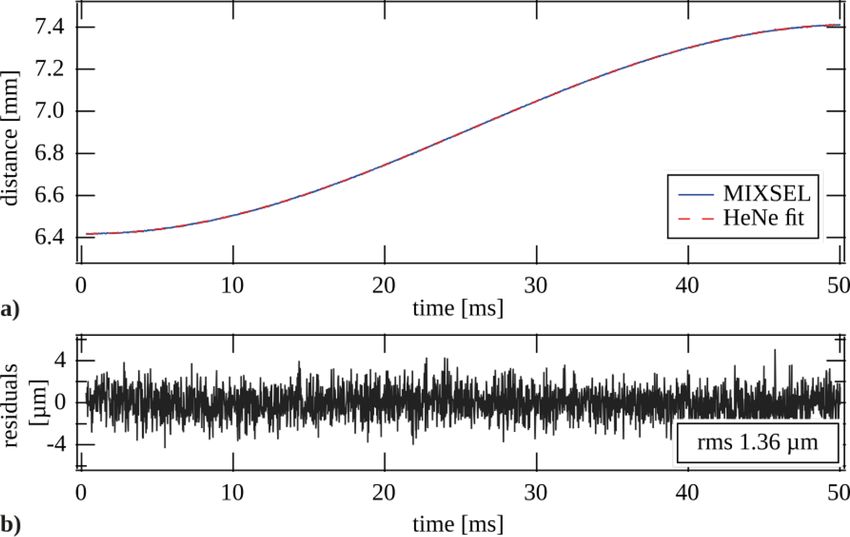
The results are shown in Figure 3(a) and show that we can reliably trace the 10 Hz shaker motion.
It should be noted that this measurement was conducted around an absoulute distance of 281 mm,
or five times the ambiguity range of the laser. The measured distance is accordingly folded into
the ambiguity range. Figure 3(b) displays the residuals between our LIDAR measurement and
the Michelson reference with an rms deviation of 1.36 µm.
Fig. 3. (a) The distance measured with the dual-comb MIXSEL around 281 mm (solid blue)
is folded into the ambiguity range and traces the 10 Hz motion of the shaker. It coincides
with the reference recording from the Michelson interferometer (dashed red). (b) The
residuals between dual-comb ranging and Michelson interferometer reveal an rms deviation
of 1.36 µm.
4. Dual-comb solid state laser ranging
After exchanging all optics to match the emission wavelength of Yb:CaF2 , we perform an
equivalent set of experiments with the free-running dual-comb Yb:CaF2 laser. With the lower
pulse repetition rate of this laser, we reduce the sampling rate and can record longer traces. The
analog BP filters are replaced by LP filters with a 3 dB cutoff frequency at 48 MHz to suppress
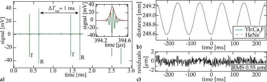
the pulse repetition rates in the radio frequency signal. Figure 4(a) shows the time domain
recording with the signal repeating approximately every 1/∆frep ≈ 1 ms. The significantly higher
signal-to-noise-ratio of the solid-state laser data is due to the higher power available in the
setup when compared to the MIXSEL. The inset displays an individual interferogram as well as
the magnitude of its analytic signal. The delay increment between subsequent pairs of pulses,Research Article Vol. 29, No. 16 / 2 August 2021 / Optics Express 24916
2 , is larger in the dual-comb solid-state laser, and the pulses are
given approximately by ∆frep /frep
shorter. Consequently, the dual-comb interferogram consists of fewer oscillations. Additionally,
interferogram and envelope show lower noise compared to the MIXSEL, such that an additional
digital BP filter can be omitted in data analysis.
Fig. 4. (a) Target (T) and reference (R) interferograms recorded with the free-running
dual-comb Yb:CaF2 laser repeat every ∆Trep ≈ 1 ms. The shorter pulses of the solid-state
laser result in shorter interferograms with fewer cycles (inset, green). Less noise on the
analytic signal (inset, red) avoids the need for additional digital filters. (b) The dual-comb
Yb:CaF2 laser (solid blue) reliably traces the absolute distance to the shaker of 248 mm within
its ambiguity range. The measurement coincides with the reference from the Michelson
interferometer (dashed red). The residuals amount to an rms deviation of 0.55 µm. (c)
Difference between the two traces in (b).
The approach to data analysis is identical to the MIXSEL. The lower update rate of 952 Hz
yields only 475 full signal periods over the experiment time of 500 ms. Figure 4(b) compares the
retrieved distance measurements to the Michselson interferometer reference with the residuals
shown in Figure 4(c). As with the MIXSEL, the data reveals the 10 Hz shaker motion. With the
longer cavity length of the solid-state laser, this measurement yields the absolute distance around
249 mm within the first ambiguity range of the system. The residuals over the measurement
period amount to an rms deviation of 0.55 µm.
5. Conclusion
In our experiments, we have shown that reliable and precise time-of-flight distance measurements
within the ambiguity range are possible with free-running dual-comb semiconductor and solid-
state laser systems. With the dual-comb MIXSEL the ambiguity range is 54.8 mm, and within one
ambiguity range we demonstrate distance measurements with sub-2-µm precision at an update
rate of above 50 kHz. Higher update rates could be achieved with a higher difference in pulse
repetition rate, that can reach megahertz for the dual-comb MIXSEL as demonstrated in [23,28].
The dual-comb Yb:CaF2 solid-state laser achieves ranging with a precision well below 1 µm
and has an ambiguity range of 1098.4 mm. The repetition rate difference ∆frep of the Yb:CaF2
laser is set to 952 Hz. For faster measurements, these values could be increased somewhat before
the onset of aliasing. With spectral filtering or scaling the pulse repetition rate of the lasers, it
would be possible to increase ∆frep significantly and achieve much higher update rates.
To increase the ambiguity range of the systems to exceed the cavity length, one can exploit
the Vernier effect by interchanging the roles of the two frequency combs [13]. The theoretical
extended ambiguity range under these conditions would be RA = vg,air /2∆frep = 2.8 km for
the MIXSEL and 157 km for the solid-state laser. Under these conditions, both lasers are
attractive for ground and drone based ranging solutions. In particular the higher update rate
of the MIXSEL, when combined with the full extended ambiguity range, could make it highly
suitable for applications requiring fast, long-range measurements.Research Article Vol. 29, No. 16 / 2 August 2021 / Optics Express 24917
Funding. Schweizerischer Nationalfonds zur Förderung der Wissenschaftlichen Forschung (40B2-0_180933).
Disclosures. The authors declare no conflicts of interest.
Data availability. Data underlying the results presented in this paper are not publicly available at this time but may
be obtained from the authors upon reasonable request.
References
1. R. Dändliker, R. Thalmann, and D. Prongué, “Two-wavelength laser interferometry using superheterodyne detection,”
Opt. Lett. 13(5), 339–341 (1988).
2. C. C. Williams and H. K. Wickramasinghe, “Absolute optical ranging with 200-nm resolution,” Opt. Lett. 14(11),
542–544 (1989).
3. J. A. Stone, A. Stejskal, and L. Howard, “Absolute interferometry with a 670-nm external cavity diode laser,” Appl.
Opt. 38(28), 5981–5994 (1999).
4. H.-J. Yang, J. Deibel, S. Nyberg, and K. Riles, “High-precision absolute distance and vibration measurement with
frequency scanned interferometry,” Appl. Opt. 44(19), 3937–3944 (2005).
5. S. M. Beck, J. R. Buck, W. F. Buell, R. P. Dickinson, D. A. Kozlowski, N. J. Marechal, and T. J. Wright, “Synthetic-
aperture imaging laser radar: laboratory demonstration and signal processing,” Appl. Opt. 44(35), 7621–7629
(2005).
6. K. Minoshima and H. Matsumoto, “High-accuracy measurement of 240-m distance in an optical tunnel by use of a
compact femtosecond laser,” Appl. Opt. 39(30), 5512–5517 (2000).
7. N. Bobroff, “Recent advances in displacement measuring interferometry,” Meas. Sci. Technol. 4(9), 907–926 (1993).
8. R. Fox and L. Hollberg, “Wavelength references for optical interferometry,” in CLEO/Europe. 2005 Conf. Lasers
Electro-Optics Eur. 2005., vol. 44 (IEEE, 2005), p. 456.
9. N. Schuhler, Y. Salvadé, S. Lévêque, R. Dändliker, and R. Holzwarth, “Frequency-comb-referenced two-wavelength
source for absolute distance measurement,” Opt. Lett. 31(21), 3101–3103 (2006).
10. Y. Salvadé, N. Schuhler, S. Lévêque, and S. Le Floch, “High-accuracy absolute distance measurement using frequency
comb referenced multiwavelength source,” Appl. Opt. 47(14), 2715–2720 (2008).
11. P. A. Elzinga, F. E. Lytle, Y. Jian, G. B. King, and N. M. Laurendeau, “Pump/Probe Spectroscopy by Asynchronous
Optical Sampling,” Appl. Spectrosc. 41(1), 2–4 (1987).
12. K. J. Weingarten, M. J. W. Rodwel, and D. M. Bloom, “Picosecond optical sampling of GaAs integrated circuits,”
IEEE J. Quantum Electron. 24(2), 198–220 (1988).
13. I. Coddington, W. C. Swann, L. Nenadovic, and N. R. Newbury, “Rapid and precise absolute distance measurements
at long range,” Nat. Photonics 3(6), 351–356 (2009).
14. T.-A. Liu, N. R. Newbury, and I. Coddington, “Sub-micron absolute distance measurements in sub-millisecond times
with dual free-running femtosecond Er fiber-lasers,” Opt. Express 19(19), 18501–18509 (2011).
15. B. Lin, X. Zhao, M. He, Y. Pan, J. Chen, S. Cao, Y. Lin, Q. Wang, Z. Zheng, and Z. Fang, “Dual-comb absolute
distance measurement based on a dual-wavelength passively mode-locked laser,” IEEE Photonics J. 9(6), 1–8 (2017).
16. D. Hu, Z. Wu, H. Cao, Y. Shi, R. Li, H. Tian, Y. Song, and M. Hu, “Dual-comb absolute distance measurement of
non-cooperative targets with a single free-running mode-locked fiber laser,” Opt. Commun. 482, 126566 (2021).
17. J. Fellinger, G. Winkler, P. Aldia, A. S. Mayer, V. Shumakova, L. W. Perner, V. F. Pecile, T. Martynkien, P. Mergo, G.
Sobo, and O. H. Heckl, “Simple approach for extending the ambiguity-free-range of dual-comb ranging,” arXiv
preprint arXiv:2106.05394 (2021).
18. M. G. Suh and K. J. Vahala, “Soliton microcomb range measurement,” Science 359(6378), 884–887 (2018).
19. P. Trocha, M. Karpov, D. Ganin, M. H. P. Pfeiffer, A. Kordts, S. Wolf, J. Krockenberger, P. Marin-Palomo, C.
Weimann, S. Randel, W. Freude, T. J. Kippenberg, and C. Koos, “Ultrafast optical ranging using microresonator
soliton frequency combs,” Science 359(6378), 887–891 (2018).
20. D. J. Maas, A. R. Bellancourt, B. Rudin, M. Golling, H. J. Unold, T. Südmeyer, and U. Keller, “Vertical integration
of ultrafast semiconductor lasers,” Appl. Phys. B 88(4), 493–497 (2007).
21. J. Nürnberg, C. G. E. Alfieri, Z. Chen, D. Waldburger, N. Picqué, and U. Keller, “An unstabilized femtosecond
semiconductor laser for dual-comb spectroscopy of acetylene,” Opt. Express 27(3), 3190–3199 (2019).
22. B. Willenberg, J. Pupeikis, L. M. Krüger, F. Koch, C. R. Phillips, and U. Keller, “Femtosecond dual-comb Yb:CaF2
laser from a single free-running polarization-multiplexed cavity for optical sampling applications,” Opt. Express
28(20), 30275–30288 (2020).
23. S. M. Link, A. Klenner, M. Mangold, C. A. Zaugg, M. Golling, B. W. Tilma, and U. Keller, “Dual-comb modelocked
laser,” Opt. Express 23(5), 5521–5531 (2015).
24. S. Schilt, N. Bucalovic, V. Dolgovskiy, C. Schori, M. C. Stumpf, G. D. Domenico, S. Pekarek, A. E. H. Oehler, T.
Südmeyer, U. Keller, and P. Thomann, “Fully stabilized optical frequency comb with sub-radian ceo phase noise
from a sesam-modelocked 1.5-µm solid-state laser,” Opt. Express 19(24), 24171–24181 (2011).
25. T. D. Shoji, W. Xie, K. L. Silverman, A. Feldman, T. Harvey, R. P. Mirin, and T. R. Schibli, “Ultra-low-noise
monolithic mode-locked solid-state laser,” Optica 3(9), 995–998 (2016).
26. M. Mangold, C. A. Zaugg, S. M. Link, M. Golling, B. W. Tilma, and U. Keller, “Pulse repetition rate scaling from 5
to 100 GHz with a high-power semiconductor disk laser,” Opt. Express 22(5), 6099–6107 (2014).Research Article Vol. 29, No. 16 / 2 August 2021 / Optics Express 24918
27. R. Liao, H. Tian, W. Liu, R. Li, Y. Song, and M. Hu, “Dual-comb generation from a single laser source: principles
and spectroscopic applications towards mid-ir–a review,” JPhys Photonics 2(4), 042006 (2020).
28. S. M. Link, D. J. H. C. Maas, D. Waldburger, and U. Keller, “Dual-comb spectroscopy of water vapor with a
free-running semiconductor disk laser,” Science 356(6343), 1164–1168 (2017).You can also read