DURACODE SERIES - INKJET, INC.
←
→
Page content transcription
If your browser does not render page correctly, please read the page content below
DuraCode Series
                  Continuous Inkjet Printer

        OPERATION MANUAL

                      www.inkjetinc.com | 1-800-280-3245

         Compliance Information
This equipment has been tested and found to comply with the limits for a Class A
digital device, pursuant to part 15 of the FCC Rules. These limits are designed to
provide reasonable protection against harmful interference when the equipment is
operated in a commercial environment. This equipment generates, uses, and can
radiate radio frequency energy and, if not installed and used in accordance with the
instruction manual. Operation of this equipment in a residential area is likely to cause
harmful interference, in which case the user will be required to correct the
interference at his own expense.

2006/42/EC                                     Machinery Directive
2014/35/EU                                     Low Voltage Directive
2014/30/EU                                     Electromagnetic Compatibility Directive

EN ISO 12100:2010                              Safety of machinery – General principles
for
                                               Design – Risk assessment and risk
reduction

EN 60204-1:2006+A1:2009+AC:2010                Safety of machinery – Electrical equipment
of
                                               machines – General requirements

EN 55032:2015                                  Electromagnetic compatibility of
multimedia
                                               Equipment – Emissions requirements

EN 55024:2010+A1:2015                          Information technology equipment –
                                               Immunity characteristics – Limits and
methods
                                               of measurement

EN 61000-3-2: 2014                             Electromagnetic compatibility – Part 3-2
Limits
                                               for harmonic current emissions

EN 61000-3-3:2013                              Electromagnetic compatibility – Part 3-3
Limits
                                               of voltage changes, voltage fluctuations
and
                                               flicker in low-voltage supply systems
Content
About the DuraCode DURACODE 200 SERIES
KEYPAD Printer ------------------------------------------ 1
1. Safety Guidelines ------------------------------------- 2
1.1 Introduction------------------------------------------------------------------------ 2
1.2 General Safety Guidelines ---------------------------------------------------- 2
1.3 Fluid Safety Guidelines -------------------------------------------------------- 3
1.4 In Case of Emergency---------------------------------------------------------- 3
2. Introduction -------------------------------------------- 4
2.1 Appearance overview----------------------------------------------------------- 4
2.2 Control Panel --------------------------------------------------------------------- 4
2.3 Printhead -------------------------------------------------------------------------- 5
2.4 Ink Core ---------------------------------------------------------------------------- 5
2.5 Main Screen ---------------------------------------------------------------------- 6
2.6 Menu Analysis -------------------------------------------------------------------- 7
2.6.1 PRINT DATA ---------------------------------------------------------------------- 7
2.6.2 USER FIELD -------------------------------------------------------------- 7
2.6.3 PRINT SET ---------------------------------------------------------------- 8
2.6.4 INK SYSTEM ------------------------------------------------------------- 9
2.6.5 MACHINE SET --------------------------------------------------------- 10
2.6.6 F4 Password ------------------------------------------------------------ 11
2.6.7 W) User Defined ------------------------------------------------------- 11
2.6.8 Photocell 1 Set --------------------------------------------------------- 12
2.6.9 Photocell 2 Set --------------------------------------------------------- 12
2.7 Specifications ------------------------------------------------------------------- 13
3. Printer Operation ----------------------------------- 143.1 Commission --------------------------------------------------------------------- 14
3.2 Start The Printer --------------------------------------------------------------- 15
Content
3.2.1 Start Jet ------------------------------------------------------------------ 15
3.2.2 Inkjet Observation ----------------------------------------------------- 16
3.2.3 Drops Observation ----------------------------------------------------- 17
3.3 Stop Jet -------------------------------------------------------------------------- 18
3.3.1 Stop Jet and Clean ---------------------------------------------------- 18
3.3.2 Stop and Clean (Power off during use of the printer) -------- 18
3.3.3 Stop and Clean (long-term stop of use) ------------------------- 18
3.4 Create Message --------------------------------------------------------------- 19
3.4.1 Create a Sample Message ------------------------------------------ 19
3.5 Create/Edit User Field ------------------------------------------------------- 21
3.5.1 Time User Field -------------------------------------------------------- 21
3.5.2 Additional remarks for time user field ---------------------------- 22
3.5.3 Barcode User Field --------------------------------------------------- 23
3.5.4 Additional remarks for Barcode User Field ---------------------- 24
3.5.5 Counter User Field ---------------------------------------------------- 25
3.5.6 Instructions for Items in the Counter ----------------------------- 26
3.5.7 Logo User Field -------------------------------------------------------- 27
3.5.8 Code User Field ------------------------------------------------------- 29
3.5.9 External data User Field --------------------------------------------- 30
3.6 Message Parameters -------------------------------------------------------- 31
3.6.1 Modify message parameters and contents --------------------- 31
3.7 Print Mode Setting ------------------------------------------------------------ 32
3.7.1 Single Printing Mode ------------------------------------------------- 32
3.7.2 Continuous Printing Mode ------------------------------------------ 33
3.7.3 Measure mode --------------------------------------------------------- 34
3.7.4 Traverse Printing Mode ---------------------------------------------- 353.7.5 Repeat Printing Mode ------------------------------------------------ 36
4. Maintenance ------------------------------------------ 37
Content
4.1 Diagnostic Screen ------------------------------------------------------------- 37
4.2 Failure and warning icons --------------------------------------------------- 38
4.2.1 Failure icons ------------------------------------------------------------- 38
4.2.2 Warning icons ----------------------------------------------------------- 39
4.3 Troubleshooting ---------------------------------------------------------------- 40
4.4 Wash Nozzle -------------------------------------------------------------------- 41
4.5 Ink Jet Alignment -------------------------------------------------------------- 41
4.6 Clean Ink System -------------------------------------------------------------- 42
4.7 Sensor and Encoder Wiring Diagram ------------------------------------ 43
4.7.1 Sensor Diagram -------------------------------------------------------- 43
4.7.2 Encoder Diagram ------------------------------------------------------ 43About the DuraCode DURACODE 200
SERIES KEYPAD Printer
Overview
The DuraCode DURACODE 200 SERIES KEYPAD printer system is a
fast, reliable, non-contact inkjet printer designed to provide versatile,
uninterrupted operation in factory environments. It is used to apply sell-by
dates, batch codes, logos, barcodes, and other variable information to a
wide range of substrates on the production line using a continuous inkjet
printing technology. It is designed with a stainless-steel enclosure with an
IP55 rating (International Protection rating against dust and water).
Operating Simplicity
• Convenient side panel ‘Power On/Power off’ button
• Simplistic message creation using the full size QWERTY keyboard,
function keys, and general control keys.
Printhead Design
• Minimal ink build-up and longer intervals between cleaning.
• Robust sleek design for use in the harshest industrial environments.
• Standard 3-meter umbilical, with other optional lengths.
• Nozzle sizes available in 40, 50, 60 micron.
• Design features an automatic flush cycle when stopping the system to
clean the printhead and maintain clean starts allowing for longer
intervals between manual cleaning.
Viscosity Control
• Advanced system for monitoring and controlling ink viscosity.
Diagnostics
• Built in diagnostic functions.
• On-screen system event messages.
Operating the Printer
Printer operations are controlled on the front of the printer using the full-
size keyboard, general control keys, function keys, LED indicators and an
LCD display screen.
Function Key Driven Interface
• Simple menu-based user interface
• Keyboard shortcuts provide direct access to key printer functions
• Easy access to message creation and editing functions
• WYSIWYG message display
Password Protected Functionality
• Access to printer functions can be controlled by password-controlled
user levels
• There are three user levels to best suit operator needs.
Message Storage
• Up to 100 message capacity
• Easy message selection with preview facility
Page 11. Safety Guidelines
1.1 Introduction
The intended use of the DuraCode series printer is to print information directly
onto a product. Use of this equipment in any other fashion may lead to
serious injury.
The safety guidelines provided in this manual are intended to educate the
operator on all safety issues, so that the printer is operated in a safe manner.
All personnel operating equipment must be aware of the hazards associated
with inkjet printers. All safety information contained within this document
should be made available to all personnel and is applicable to any person in
the printers operating environment. Only personnel who have been fully
trained on the equipment are qualified to operate it.
1.2 General Safety Guidelines
Only InkJet Inc. trained personnel should provide maintenance and installation
of equipment. Work performed by unauthorized personnel may cause
damage to the printer and may invalidate the warranty.
• DO NOT smoke or use open flames in the vicinity of the printer.
The inks and solvents contained within the printer are flammable.
• ALWAYS ensure that the printer electrical supply is isolated prior to
performing cleaning or maintenance activities. Lethal voltages are
present in the printer cabinet and printhead when mains power is
applied, which can cause death or serious injury if the correct
electrical procedures are not observed.
• Only use lint free cloths when cleaning equipment to avoid damage
to the printhead.
• DO NOT fit or remove any connector on the printer when the
power is turned on to avoid damage to printer.
• AVOID personal injury and equipment damage by using the main
power cable supplied with the equipment. The end of this cable
must be an approved, three-pole, main plug that has a protective
ground conductor. Sockets and plugs must remain clean and dry.
Always inspect cables for damage, wear, corrosion, and
deterioration.
• The printer must be connected to an AC power supply that has a
protected ground conductor and must be according to IEC
requirements or applicable local regulations.
• AVOID personal injury and equipment damage by using a suitably
grounded antistatic wrist strap when working on or handling PCBs.
Page 21.3 Fluid Safety Guidelines
The effects of solvents and inks are potentially harmful. Whenever they are
used, the following must be observed:
• BEFORE YOU START read the Material Safety Sheets. If Material
Safety Sheets have not been supplied, please contact InkJet
Incorporated for a copy.
• The printer must be installed in a well-ventilated area when
working on the printer, or with inks and solvents.
• YOU MUST wear approved safety glasses to avoid personal injury.
• YOU MUST wear approved, solvent resistant gloves when in
contact with inks and solvents to avoid personal injury.
• IMMEDIATELY after use, remove any tissue or cloth that becomes
saturated with ink or solvent. Dispose all items in accordance with
local regulations.
• STORE all inks and solvents in original containers in a well-
ventilated cabinet away from any heat sources.
• ENSURE that first aid information is readily available in the event of
ingestion, inhalation, or contact with skin or eyes. All operators
should be trained in First Aid and be aware of the effects or working
with flammable and toxic substances.
• PROLONGED breathing of make-up fluid or cleaning fluid vapor
may cause drowsiness and/or effects similar to alcoholic
intoxication. Use only in well ventilated areas.
1.4 In Case of Emergency
In an emergency you may need to stop the printer quickly. To do this:
• Switch the printer’s wall mounted electrical isolator to the off
position to shut off the electricity supply to the printer.
• Alternatively, switch the printer mains power supply switch at the
side of the printer.
• Call for medical assistance as required
If possible, the printer should not be left in this state for a long period of time
and should be restarted at the earliest possible opportunity to prevent ink
blockages. If there is a hazard that prevents safe access to the printer’s power
supply, do not attempt to shut down the printer, just vacate the area.
WARNING: IN ALL EMERGENCY CASES, REMOVE THE CASUALTY
FROM THE HAZARD AND CHECK THE MATERIAL SAFETY DATA
SHEETS FOR IMMEDIATE ACTION. EVACUATE THE CASUALTY TO
MEDICAL AID IF REQUIRED.
Page 32. Introduction
2.1 Appearance overview
Right View Front View Left View
Introduction:
1. Power button
2. Upper:Electronics Compartment 、Control Panel
3. Lower:Ink Compartment
4. Connector Panel
5. Umbilical
2.2 Control Panel
Page 42.3 Printhead
Last Chance Filter
Nozzle Connector
Printhead type
Nozzle
Charge Electrode
Nozzle Connector
Deflection Plate
Gutter Pipe
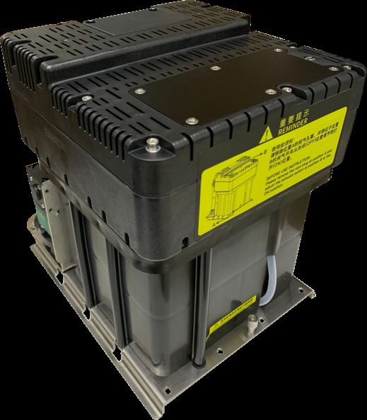
2.4 Ink Core
* Exhaust Air
Switch
Condenser
Cover
Manifold
Gear Pump Filter
Addition
Pump
Drain Pipe
Flushing
Pump
* Exhaust Vent Plug
Ink Core(Front View) Ink Core(Back View)
* Please remove the exhaust vent plug and turn on exhaust
air switch before use.
Page 52.5 Main Screen
The main screen is the default screen after the printer powered on:
1
5
2
6
3
4
Instructions:
1. The current status description area of the device;
2. A shortcut function keypad includes an user-defined function;
3. The name of the current message ;
4. The content of the current message, it’s a WYSIWYG message viewer, the
content of which is consistent with the content printed by the printer;
5. The printer icon display area contains icons such as consumables, equipment
status, warnings and faults;
6. The counter of the cumulative number of prints can be reset;
Page 62.6 Menu Analysis
2.6.1 PRINT DATA
1. It is used to select and recall the stored messages , which is equivalent to the “F2
Select Message” on the main screen.
2. Used to create and edit saved messages.
3. Used to set the default message parameters.
4. It is used to delete the messages stored in the printer.
5. It is used to copy the messages in the printer to the USB storage device.
6. It is used to copy the messages in the USB storage device into the printer.
2.6.2 USER FIELD
1. Used to create and edit saved user fields.
2. Used to delete user fields that have been stored in the printer.
3. Used to transfer the custom pattern in the printer to the USB storage device.
4. Used to copy the picture files (BMP monochrome) in the USB storage device into the
printer.
5. It is used to set the date and time code. For example, if January is printed as Jan, etc.,
in the time user field, the date and time code can be referenced by referring to a
specific letter, RR can refer to the year code, and SSS can refer to the month code, TT
can reference the day code, UU can reference the hour code, VV can reference the
minute code, some models do not include this function.
Page 72.6.3 PRINT SET
1. Used to enable or disable the printing function. if set to "Disable", the printer will
disable the printing function and prompt "High voltage not activated" in the status bar.
2. It is used to select the printing quality, standard and high quality 01~15. The higher the
high quality selection, the better the printing quality will be, but the slower the printing
speed will be.
3. It is used to set whether the main screen “F1 Manual Start/Stop Printing” is effective. If
you need to use an external sensor such as an electric eye, you need to set this option
to “Disable ”.
4. Photocell 1 Set, refer to 2.6.8 Photocell 1 setting submenu.
5. Photocell 2 Set, refer to 2.6.9 Photocell 2 setting submenu.
6. Set the encoder mode, you can set "internal", "external". When set to "External", it is
effective to use an encoder.
7. Used to reset the counter used in the current message to any value within the counter
range.
8. The product counter on the main screen can be reset to any value.
9. It is used to set the printing mode of the printer, which can be set to “Single”, “Repeat”,
“Continuous” and “Traverse”.
10. When the print mode is set to “Continuous”, use this menu to set “Internal Interval”
(valid when the shaft encoder is internal), “External Interval” (valid when the shaft
encoder is external) and “Measure” related options.
11. When the print mode is set to “Repeat ”, use this menu to set the “Print times” to
control the print times per trigger.
12. When the print mode is set to “Traverse”, use this menu to set the options for traverse
printing;
13. It is used to set the ratio between the actual effective value and the set value of the
message width, delay and message interval. Default value is 1.
Page 82.6.4 INK SYSTEM
1
2
3
4
5
6
7
8
9
10
11
12
13
14
15
16
1. Flushing the nozzle blockage automatically.
2. After performing , open the printhead cover and use cleaning agent to clean the nozzle
manually.
3. It is used to control the pump, valve and other parts separately.
4. Used for cleaning umbilical , only for commissioning engineers to use when debugging.
5. It is used to quickly start the jet, without auto cleaning.
6. For quick stop inkjet without auto cleaning.
7. For setting the ink type, built-in B600, 601, A630, 680, 619, 669, 2630, 2631, 263, 273
and 630.
8. Used to set the ink viscosity, manual / auto optional;
9. Used to calibrate the standard reference pressure;
10. For the entire ink system cleaning, follow the on-screen instructions
11. Used to exhaust the air, usually for commissioning.
12. Open/Close the positive air to the printhead after positive air pump installed.
13. Used for the first time cleaning after the printer is assembled
14. Used to select the printhead type, according to the mark on the print module base.
15. For setting the time for automatic printer shutdown (1 to 99 hours)
16. It is used to fill the mixer tank with ink to the OK level. It is used when the machine is
first time use.
Page 92.6.5 MACHINE SET
Configuration
1
2
3
4
5
6
7
8
9
10
11
12
13
14
15
16
17
18
19
20
21
22
1. Used to disable the automatic shutdown caused by charge fault.
2. Used to disable the automatic shutdown caused by the gutter fault.
3. used to set the modulation value, auto mode only takes effect during startup.
4. Used to set the charge value.
5. Used to set the running pressure.
6. Used to set the heater target temperature.
7. Used to set the phase charge value.
8. Used to set the phase offset value.
9. Used to check the current software information.
10. Used to define the shortcut function on main screen.
11. Used to enable /disable the keyboard buzzer.
12. Used to set the system time and date, the frozen time setting is in this menu;
13. Used to set the EHT Grade, range 1-3, the higher the value, the lower the sensitivity..
14. Used to set the output range of the 7KV extra high tension which is matched with the
Height value in F3 Parameters.
15. Used to change the gutter mode.
16. Used for serial port configuration.
17. Used to set the printer language.
18. Used to check the maintenance time, and the ink cartridge type (750ml/375ml) can be
selected here.
19. Used to Enable /Disable the backlight Saver.
20. Used to set the font style for 0,1 and 5 (Some fonts will not take effect)
21. Used to calibrate the EHT standard values
22. Used to check the expiration infos for the cartridges.
Page 102.6.6 F4 Password
Only "Enter Password" menu is displayed before the password is entered.
1. Used to enter password;
2. Used to exit the password to level 0 (The lowest permission).
3. Used to set the password protection level of each function of the system.
4. Used to modify the user password;
5. Used to modify the maintenance password;
2.6.7 W) User Defined
1. Users can customize frequently used functions to this area;
Page 112.6.8 Photocell 1 Set
1. Select photocell 1 to be active by high or low level when triggering printing.
2. The way of the external photocell triggers printing, Gate or Trigger optional .
3. Within this time, the time interval between the trigger level and the trigger level can be
obtained again (such as avoiding secondary sensing in the same product);
4. Select how to handle the photocell signal;
5. Open/Close the secondary sensing prompt;
6. Set the number of times the photocell is sensed before it is triggered effectively.
7. This option is associated with the sixth “Signal Times” setting, and the first few times
within the set number of sensing times are valid;
2.6.9 Photocell 2 Set
1. Select photocell 2 to be active by high or low level when triggering printing.
2. Disable, Reset counter, Traversing print control , Reset traversing print , Opposite print
and Reset detection & counting are optional.
3. The way of the external photocell triggers printing, Gate or Trigger are optional.
Page 122.7 Specifications
Electrical specifications
Voltage 100V-240V AC
Frequency 50Hz-60Hz
Energy consumption 120(W) maximum value
Weight
Net weight 27KG
Dimensions
Cabinet 345L * 286W * 570H
Printhead diameter 35mm / 41mm
Printhead length 260mm / 250mm
Nozzle size 70,60,50,40 μm
Umbilical length 2700mm
Environment specifications
Operating temperature 5℃ to 45℃
Ambient temperature replacing
10℃ per hour at most
rate
Relative humidity 0-90%, non-frosting
Storage temperature 5℃-45℃ (original package)
Page 133. Printer Operation
3.1 Commission
Printer needs to be filled with ink and exhaust air before use.
1. Open the lower cabin door and install the correct ink and makeup to the correct
position according to the label .
2. Pull out the ink system, remove the exhaust air plug at the bottom (Refer to step A.)*,
and use a screwdriver to open the top exhaust air switch (Refer to step B.)* as shown in
figure:
B. The exhaust air switch must
! be turned on before use.
A. Remove the exhaust
! air plug
3. Push the ink system into the cabin and close the lower cabin door .
4. Enter the INK SYSTEM menu, perform the A)Fill Mixer program wait for about 30
minutes until the screen shows “Fill Mixer Tank Finish”.
5. Enter the INK SYSTEM menu and perform E) Exhaust Air program to complete ink
way priming. Screen prompt will advise when complete. NOTE: Ink will come from the
gutter, place a catcher under the printhead.
6. Clean the printhead.
* During normal use of the printer, the exhaust vent plug A needs to be removed, and the exhaust
air switch B needs to be opened , otherwise it will cause printer failure.
* Executing a Fill Mixer may result in an ink remaining percentage deviation.
Page 143.2 Start The Printer
3.2.1 Start Jet
1. Connect the printer to an appropriate power source.
2. Open the printer head cover, check various components in the printhead, and check
that various components are clean and dry.
3. Put on the printhead cover, press the power button at the right side of the printer, and
wait for the screen to enter the main operation interface
4. Press to start the program for about 3 minutes. The interface is as follows:
5. Observe the status indicator and the main screen. When the green LED is lit, the
startup is completed. The interface is as follows:
* Frequent start/stop jet will cause the ink to be diluted, which will affect the printing quality .
Page 153.2.2 Inkjet Observation
Side View :
Inkjet
Charge Nozzle
Electrode
The inkjet is at the central
position of the gutter pipe
Front View:
The inkjet is about 1/4 of the right side
of the gutter pipe
Nozzle
Charge
Electrode
Page 163.2.3 Drops Observation
The drops are generated after printer has started normally. It directly affects the printing
effect and printing durability. Good drops roughly depend on the following three factors:
Appropriate and stable pressure
Correct ink viscosity
Correct modulation value
The observation method is as follows:
1. Take out the magnifying glass in the standard and place it on the red LED light about
15mm.
2. Adjust the distance of the magnifying glass up and down slightly to observe the drops
shown in the figure below:
3. The drops are disconnected at the middle of the charge electrode. The shape of the
drops before disconnection can refer to the following figure:
Pool conditions To be avoided Good
* The shape of drops can be adjusted through the "Modulation Set Level" in the MACHINE
SET menu;
Page 173.3 Stop Jet
3.3.1 Stop Jet and Clean
1. Press button, it lasts for about 4 minutes, the interface is as follows:
2. During cleaning after shutdown, remove the Printhead cover and observe if the
printhead is dirty. If needed clean the printhead with the necessary cleaning agent.
3. Only after the interface is shown as below, the power can be turn off, Otherwise
some of the tubes will be blocked, causing permanent damage.
3.3.2 Stop and Clean (Power off during use of the printer)
If abnormal stop is caused due to power off, inkjet must be restarted at the
earliest time after power on. It shall be normally cleaned and shut down after
planned shutdown else some ink tubes of the printer may be blocked, causing
permanent damage to the printer.
3.3.3 Stop and Clean (long-term stop of use)
Due to the quick-dry property of the ink, if long-term stop are needed, it’s always
suggested to drain the ink and clean the system. For details, check the section
“4.6 Drain” and “4.7 Clean the ink system” .
Page 183.4 Create Message
3.4.1 Create a Sample Message
For example: Create the following message as follows with a file name “TEST” to create
this message:
Follow these steps:
1. Enter the PRINT DATA menu,select E) Edit/Create Message - Create New
Message, confirm and enter the interface as shown in the following figure:
2. Input file name TEST, then press enter key, as shown in the following figure:
* Press the CUSTOM button on this interface to pop up the Help window.
3. Press F1 repeatedly. When the editing state is displayed as "16 High " then input
“DURACODE” .
Page 194. Press F2 to select the “R” User Field (refer to 3.5.7 Logo), press the Enter key to
insert, as shown below:
* In the editing interface, the F2 function is “ Insert User Field ”.
5. After the content is entered, press the 7DE to switch to the “Save Exit” button and
confirm.
Message Edit Additional Instructions:
a. + key , move the cursor in units of one pixel.
b. + key, move the cursor left and right in units of 100 pixels.
Bold, reverse, etc. for specific characters:
a. In the editor , Press to switch to the “Select” mode.
b. Use + to select the characters you want to adjust.
c. After selected , press to adjust the property for the characters.
d. After adjusted , press to continue editing the normal content.
Page 203.5 Create/Edit User Field
3.5.1 Time User Field
Follow the steps below to create :
1. Enter the USER FIELD menu,select E) Edit/Create User Field - N) New User
Field, as shown in the figure below:
2. Input a file name, switch “Attr” to “Time” then confirm , as shown in the figure
below:
3. Fill the Time Code* in the “Text”, and switch the “Type” to the type needed, if
the printing result is digital numbers, just keep it as “Value”.
4. Press Enter to complete, then press F2 while editing the message to insert
this field into the message.
* Time Code definition please refer to “3.5.2 Time User Field Additional instructions”.
Page 213.5.2 Additional remarks for time user field
Definition of Time User Field Code
Code Definition
A Monday to Sunday
BC Year
DE Month
FG Day
HI Hour
JK Minute
LM Second
OO Week
PPP Day
RR Year Code
SSS Month Code
TT Day Code
UU Hour Code
VV Minute Code
1. Actual printing date and time = system current time + number of days of Expiry term. If
it is required to print the current time, the Expiry term is set as 0.
2. In the printing information, the time user field size is determined by the fonts
selected during insertion.
3. When the "Print Form" is Data Matrix or QR Code, the "Width" and "Height”
shall be set according to the standard. For details, see the section of
preparation of QR code & bar code User Field.
Page 223.5.3 Barcode User Field
The standards of barcode supported by the type include:
QR Code (Figure 1), Data Matrix (Figure 2), Code39 (Figure 3), Code128 (Figure 4),
EAN8 (Figure 5), EAN13 (Figure 6), EAN128 (Figure 7), UPC-A(Figure 8)
Figure 1 Figure 2 Figure 3 Figure 4 Figure 5
Figure 6 Figure 7 Figure 8
1. Enter the USER FIELD menu,select E) Edit/Create User Field - N) New User
Field, as shown in the figure below:
2. Input a file name, switch “Attr” to “Text” then confirm , as shown in the figure
below:
3. Fill the contents of Barcode to “Text" field, and switch the “Type" to the Barcode
required.
4. When the "Type" is Data Matrix or QR Code, it is required to set the "Width" and
"Height".
Page 233.5.4 Additional remarks for Barcode User Field
1. The size (Height x Width) supported by Data Matrix include 10x10, 12x12,
14x14, 16x16, 18x18, 20x20, 22x22, 24x24, 26x26, 32x32, 8x18, 8x32, 12x26,
16x36, 16x48.
2. The size (height x width) supported by QR Code include 21x21, 25x25, 29x29,
33x33.
3. If the prompt of “Unsupported size" or "Coding error" appears, please modify it
to larger height and width for saving.
4. Code39 and Code128 are the Barcodes with variable length, EAN8 can code
the character string with length of 7, and EAN13 can code the character string
with length of 12.
5. UPC-A can encode 11 digits and the twelfth check digit is automatically
generated.
6. The width of the Barcode is automatically generated with the printer, and the
height is determined by the current font when the message is inserted in the
User Field. It is not required for the user to adjust the "Width" and “Height”.
Page 243.5.5 Counter User Field
1. Enter the USER FIELD menu,select E) Edit/Create User Field - N) New User Field,
as shown in the figure below:
2. Input a file name, switch “Attr” to “Text” then confirm , as shown in the figure below:
* Instructions of each items refer to “ 3.5.6 Instructions for items in the Counter ”.
Page 253.5.6 Instructions for Items in the Counter
1. Start value : Start value of the counter.
2. End value : End value of the counter
3. Reset value : Value to be reset when the function of "Reset Counter" of the Photocell 2
is used.
4. Step size : 1 at default, if set as 2, the counter will become "1, 3, 5, 7, ...".
5. Direction : Increase or decrease can be selected.
6. Repeat Count : 1 at default, printing times of each current value. For example, if set as
2, each counter will be printed for 2 times.
7. Leading Char : Leading character in front of the counter. For example, a counter range
from 1 to 999, when the print counter is “1" and the leading character is "blank space",
the printing result is "1". When the leading character is "0", the printing result will
become "001".
8. INC/DEC : It is used for nesting use between all the counters in the printer.
9. Type : The counter can be converted to printing in special form, such as 1D barcode
and 2D Barcode. For more details please refer to “3.5.4 Additional remarks for Barcode
User Field”.
10. Mod Count : 10, 16, 26, 32, 34, 36 optional.
11. Exclude Char : When 32 or 34 Mod is selected, 4 or 2 unprinted letters can be
customized.
12. Alarm Delay : Set the delay of the counter alarm, available for system build-in
“COUNTER" only
13. Alarm Duration : Set the duration of the counter alarm, available for system build-in
“COUNTER" only
14. Alarm Value : Set the value of the counter alarm, which needs to be within the Start
and End Value.
15. Hidden Times : Set the number of times this counter needs to be hidden in the
message. The default value is "0", indicating that it is not hidden.
16. Print Times : Set the number of times this counter needs to be printed in the message.
The default value is 1. For example, when the Hidden Times and the Print Times are
1, the print is performed once and disappears once.
17. Trailing Char : Set the suffix following the counter, the default is empty.
Page 263.5.7 Logo User Field
The Logo User Field can create the customized logo of maximum 34 dots height ( F530/
F530Plus only support 25 dots ).
1. Enter the USER FIELD menu,select E) Edit/Create User Field - N) New User Field,
as shown in the figure below:
2. Input a file name, switch “Attr” to “Logo” then confirm , as shown in the figure below:
3. Operation instructions for logo are shown in the following table:
Key combination Function
Move the cursor by a dot
+ Move the cursor by a dot, and fill the dot
+ Move the cursor by a dot, and delete the dot
Reverse the current dot, draw dot / delete dot
Page 271
4. After drawing, press the “F1 " key to set the logo size, as shown in the following figure:
* Press the CUSTOM button on this interface to pop up the Help window.
2
5. Complete logo size setting, press Enter to confirm the size, press F2 to save and exit.
3
Then it can be called and printed .
Additional remarks for setting logo size:
1. The default canvas size is 100 dots wide and 25 dots high;
2. Use + key to rapidly move the box for setting logo size;
3. In message editor , press F2 can call the user fields list .
Page 283.5.8 Code User Field
This function can integrate multiple User Fields ( Clock, counter and text ) in to generate a
code.
1. Enter the USER FIELD menu,select E) Edit/Create User Field - N) New User Field,
as shown in the figure below:
2. Input a file name, switch “Attr” to “Code” then press Enter to confirm , When the
cursor hovers between Content 1 and Content 6, press F2 to insert in sequence the
User Fields to be combined. as shown in the figure below:
Note:
When the code type is selected as Data Matrix or QR code, the Barcode Width and
Height shall be set. For more details please refer to “ 3.5.4 Additional remarks for Barcode
User Field ”
Page 293.5.9 External data User Field
The function can receive the external data predefined by the user and print them in
sequence. The preparation steps are as follows:
1. Enter the USER FIELD menu,select E) Edit/Create User Field - N) New User Field,
as shown in the figure below:
2. Input a file name, switch “Attr” to “External Data” then press Enter to confirm, as
shown in the figure below:
Setting analysis:
a. Number of Char : the bit of data transmitted from the computer to the ink jet printer.
b. "X0" at the upper right corner of the external data editing interface is the identification
code for communications with the external data User Field. Please correspond it with
the setting of "User Field" in the computer software.
c. When the Type is selected as Data Matrix or QR code, the Width and Height shall be
set. For more details please refer to “ 3.5.4 Additional remarks for Barcode User Field ”
Page 303.6 Message Parameters
3.6.1 Modify message parameters and contents
In the main screen, press the F3 key to enter the interface to modify current message
contents and parameters, as shown in the figure;
1. "WYSIWYG" information editing area;
2. Parameter editing area,through to adjust parameters, width and
delay parameters can be input directly.
3. File operation area.
* Tip : Press 7DE key for cycle switching among three areas, and press the cursor key to
move the cursor in the area.
More detail about Message Parameters, please read the following table:
Parameter Range Function
Set information width, If the value is 1, the jet printing
Width 1-255
speed reaches the fastest speed under the current dots.
Height 1-10 The larger the value is, the higher character is.
Bold 0-7 Bold the current message
Set product jet printing delay time. The larger the value is,
Delay 3-10000
the longer the time delay is.
Gap 0-8 The larger the value is, the larger the character spacing is.
Inverse On / off Adjust the character jet printing up / down direction
Reverse On / off Adjust the character jet printing left / right direction
The larger the value is, the slower the speed is, and the
larger the number of dots to be printed is.
Dots 5-34
The smaller the value is, the faster the speed is, and the
smaller the number of dots to be printed is.
Page 313.7 Print Mode Setting
3.7.1 Single Printing Mode
The mode is commonly used for beer, beverage, food, daily necessities and other familiar
industries . One trigger one printing.
1. Press PRINT SET button to enter the following setting interface:
* The GRAY options indicate that the setting is invalid for the "Single Print" mode.
2. Switch the "Print Mode" to “Single" then the printer is in the single printing mode.
3. Other valid settings please refer to "2.6.3 PRINT SET Menu”.
Note:
If you want to use a sensor to trigger products , the P) F1 Manual Print must be turn off.
Page 323.7.2 Continuous Printing Mode
The mode is commonly used for building materials, pipe, steel material and other
industries. The common feature is continuous processing, messages automatic interval
printing.
1. Press PRINT SET button to enter the following setting interface:
* The GRAY options indicate that the setting is invalid for the "Continuous Print" mode.
2. Switch the "Print Mode" to “Continuous" then the printer is in the continuous printing
mode.
3. Enter " C) Continuous Print CONFIG " submenu, as shown in the following figure:
a
b
c
d
e
Setting analysis:
a. The option sets the printing interval between each messages;
Options b, c, d and e take effect after "Shaft Encode" was set as External.
4. Other valid settings please refer to “ 2.6.3 PRINT SET “ .
Page 333.7.3 Measure mode
The mode is commonly used in the wire cable, pipe and other industries requiring
labelling of number of meters , the encoder must be used .
1. Press PRINT SET button to enter the following setting interface:
* The GRAY options indicate that the setting is invalid for the Measure Mode.
2. Select the "Shaft Encoder" as "external", and select "Print Mode" as “Continuous";
3. Enter " Continuous Print Configure " submenu, as shown in the following figure:
a
b
c
d
e
Setting analysis:
a. The setting is invalid for the "Measure Print” mode.
b. Measure: The item shall be set as "Open"
c. The setting is invalid for the "Measure Print" mode.
d. For example, if the perimeter of the wheel is 250mm, the encoder with 2000 pulses
then the value of pulse per meter is: (1000÷250) x 2000 = 8000.
e. After the value of pulse per meter set, the length of each message interval within
1000mm can be set in this option.
4. Other valid settings please refer to "2.6.3 PRINT SET Menu Analysis".
Page 343.7.4 Traverse Printing Mode
The mode is commonly used in electronics, label printing, egg and other industries, and
provides highly-efficient production mode for the array type printing.
1. Press PRINT SET button to enter the following setting interface:
* The GRAY options indicate that the setting is invalid for the Traverse Mode.
2. Switch the "Print Mode" to “Traverse" then the printer is in the traverse printing mode.
3. Enter " I) Traverse Pint CONFIG " submenu, as shown in the following figure:
The setting of the figure is the traverse printing mode achieved by only 1 sensor.
The printing effect is:
When the photocell obtains 1 signal, the printer will print 6 times, 3 of them are
forward printings (each printing interval is 200), 3 times opposite printings (each
printing interval is 500), the delay of the first printing is 16 and the delay of the
fourth printing is 100.
If the printing sequence is disturbed, can try to use Print Reset to reset the forward
and opposite printings.
Page 353.7.5 Repeat Printing Mode
In this mode you can set the specific numbers of printing per trigger.
1. Press PRINT SET button to enter the following setting interface:
* The GRAY options indicate that the setting is invalid for the Repeat Mode.
2. Switch the "Print Mode" to “Repeat" then the printer is in the repeat printing mode.
a
b
c
d
e
f
Setting analysis:
a. The option sets the internal interval between each messages.
Options b. c. d. e. take effect after "Shaft Encoder" is set as “external”.
f. The option sets the printing times.
3. Other valid settings please refer to "2.6.3 PRINT SET Menu Analysis".
4. if you are not using the "Repeat" mode, please leave the "Print Times" as 1.
Page 364. Maintenance
4.1 Diagnostic Screen
In any interface, press button to enter the diagnosis screen, and the
interface is as follows:
EHT 65 113
1. Ink pressure and Ink Temperature.
2. Temp Cabinet: Actual upper cabinet temperature.
Head : Heater temperature.
3. Phase angle and Phase Profile Value.
4. Chamber : VMS tank level status.
5. VMS Set: the optimum viscosity value calculated by the system according to ambient
temperature and ink type.
Now: current actual viscosity of ink calculated by the Printer.
6. Mix: Level status of mixer tank, the normal status is OK: ON, :Low: ON, High; OFF.
7. Detection: Detection tank level status
EHT: The EHT calibration standard value
8. Freq : The Frequency of the printer.
Modulation : The current modulation value.
Page 374.2 Failure and warning icons
4.2.1 Failure icons
Icon Name Fault cause Solution
Check the leaking position. Please
Ink system leak
consult the service engineer
Mixing The solvent components in
Tank the Mixer are vaporized It is suggested to drain the old ink,
Empty after long-term storage of and fill the new ink.
the printer
Ink addiction valve blocked Remove and clean V2
Clean the nozzle with nozzle flush
Nozzle blockage
and start it up again after drying
Conduct "breakpoint check", and
Poor breakpoint adjust it to the optimum breakpoint
position
Charge The Ink jet position is Conduct “Jet alignment", and
Fault incorrect adjust it to the optimum position
The ink is out of warranty Drain the ink and replace with new
period or is polluted ink
Clean ink system and replace the
Filter blocked filter. For details, please consult the
service engineer.
The nozzle is blocked or
Clean the nozzle, clean print head,
miss aligned jet. Ink not
and start it up again after drying
entering the gutter
Gutter
Fault Long-term storage without
Soak and clean the gutter pipe with
correct stop procedure can
solvent until it becomes
cause blockage of the
unobstructed
gutter pipe
The print head has not Clean the high voltage deflection
been cleaned for a long component in the print head,
High-
time, causing excessive ink thoroughly clean and dry it, and
Voltage
accumulating around the start it up again. If the failure is still
Leak
high-voltage deflection not removed, consult the related
component service engineer.
Solvent No solvent cartridge or
Chip inserting the wrong Insert the certified solvent cartridge
Error cartridge
No ink cartridge or
Ink Chip
inserting the wrong ink Insert the certified ink cartridge
Error
cartridge
Page 384.2.2 Warning icons
Icon Name Instructions for warning
Jet printing The ink in the system is circulating and in good condition,
operation the printer is ready for printing
Jet printing The ink in the system is not circulating, the printer is in
stop stopped state, and printing cannot be conducted
Insufficient Solvent cartridge empty. Please replace with a new solvent
solvent cartridge
Insufficient Ink cartridge is empty. Please replace with the new ink
ink Cartridge
Print head The print head cover is opened, the printer cannot print. Fit
cover open the print head cover to enable printing
Viscosity Ink viscosity failure, indicates the ink is thick or thin.
failure Please consult the related service engineer.
Mixing tank The ink level in the mixer is high. Please consult the related
full service engineer.
Encoder is The current print speed is too fast. Increase the character
too fast width or reduce the printing dot number
The ink jet printer needs maintenance. Please consult the
Service
related service engineer.
Solvent level The solvent in the solvent level is empty. Please consult
empty the related service engineer.
No enough
Increase the print interval between each messages until it
time for
disappears
phasing
VMS
Chamber can Please consult the related service engineer.
not be empty
VMS
Chamber can Please consult the related service engineer.
not be full
Page 394.3 Troubleshooting
• Turn on the power supply, there is no display on screen.
Reason Solution
No voltage of the power supply Check the power supply and related fuse
• Poor jet printing character quality or incomplete character
Reason Solution
The printhead is too far from the Adjust the distance between the printhead
product and the printing surface
The character height is too small
Reset the character height
or too large
The character width is too small
Reset the character width
or too large
Observe and adjust the breakpoint. Refer
Wrong breakpoint shape
to "3.2.3 How to Observe Break-up point".
Clean the gutter pipe deposited with ink,
check and adjust the ink position in the
Ink deposited on the gutter pipe
gutter. Refer to "3.2.2 Inkjet Observation
".
The print varies in width and Determine the printing position again or
height select the rotary encoder
• No failure prompt but printing is not clear
Reason Solution
Error in print width or wrong print Adjust the print width or printing delay
on product position
No print on product Check sensor sensitivity
• Wrong or unstable Ink jet position
Reason Solution
Clean the nozzle. See “4.6 Nozzle
Nozzle blockage
cleaning".
The trained operator can replace the filter
Filter blockage
under guidance of the service engineer.
Wrong ink jet position Refer to “4.7 Ink jet adjustment".
Page 404.4 Wash Nozzle
When the nozzle is blocked, manual cleaning is required for the function. The operation
procedures are as follows:
1. Press INK SYSTEM ,select and perform F) Wash Nozzle program.
2. After the program is started, manually clean the position shown in the following figure
with cleaning agent.
USE CLEANING AGENT TO
CLEAN THE (NOZZLE) POSITION.
THE TUBING HERE WILL HAVE
AIR AND FUILDS FLOW DURING
THE FLUSHING PROCESS
4.5 Ink Jet Alignment
C D
A
B
Horizontal alignment : Slightly loosen the screw “A” and rotate the screw “B” slightly ,then
the jet stream can be horizontal moved.
Vertical alignment : Loosen the screw “C” and rotate the screw “D” slightly ,then the jet
stream can be vertical moved.
Page 414.6 Clean Ink System
Press INK SYSTEM button , perform the C) Clean Ink System program ,finish the
drain operation according to the system prompt.
Page 424.7 Sensor and Encoder Wiring Diagram
4.7.1 Sensor Diagram
4.7.2 Encoder Diagram
1.
2.
3. 1RQH
4.
Page 43Inkjet Inc. reserves the right to modify the technical characteristics of the product without prior notice.
You can also read