EN Operating instructions Control - HP-XQ (M3.7X-I) 099-00HPXQ-EW501 Observe additional system documents!
←
→
Page content transcription
If your browser does not render page correctly, please read the page content below
Operating instructions

                   Control

                   HP-XQ (M3.7X-I)
    EN

099-00HPXQ-EW501   Observe additional system documents!   13.01.2022
General instructions
                                                      WARNING
           Read the operating instructions!
           The operating instructions provide an introduction to the safe use of the products.
           • Read and observe the operating instructions for all system components, especially the sa-
             fety instructions and warning notices!
           • Observe the accident prevention regulations and any regional regulations!
           • The operating instructions must be kept at the location where the machine is operated.
           • Safety and warning labels on the machine indicate any possible risks.
             Keep these labels clean and legible at all times.
           • The machine has been constructed to state-of-the-art standards in line with any applicable
             regulations and industrial standards. Only trained personnel may operate, service and re-
             pair the machine.
           • Technical changes due to further development in machine technology may lead to a dif-
             fering welding behaviour.

In the event of queries on installation, commissioning, operation or special conditions at the
installation site, or on usage, please contact your sales partner or our customer service
department on +49 2680 181-0.
A list of authorised sales partners can be found at www.ewm-group.com/en/specialist-dealers.
Liability relating to the operation of this equipment is restricted solely to the function of the equipment. No
other form of liability, regardless of type, shall be accepted. This exclusion of liability shall be deemed ac-
cepted by the user on commissioning the equipment.
The manufacturer is unable to monitor whether or not these instructions or the conditions and methods
are observed during installation, operation, usage and maintenance of the equipment.
An incorrectly performed installation can result in material damage and injure persons as a result. For this
reason, we do not accept any responsibility or liability for losses, damages or costs arising from incorrect
installation, improper operation or incorrect usage and maintenance or any actions connected to this in
any way.

© EWM AG
Dr. Günter-Henle-Strasse 8
56271 Mündersbach Germany
Tel.: +49 2680 181-0, Fax: -244
Email: info@ewm-group.com
www.ewm-group.com

The copyright to this document remains the property of the manufacturer.
Copying, including extracts, only permitted with written approval.
The content of this document has been prepared and reviewed with all reasonable care. The information
provided is subject to change; errors excepted.
Data security
The user is responsible for backing up data of all changes from the factory setting. The user is liable for
erased personal settings. The manufacturer does not assume any liability for this.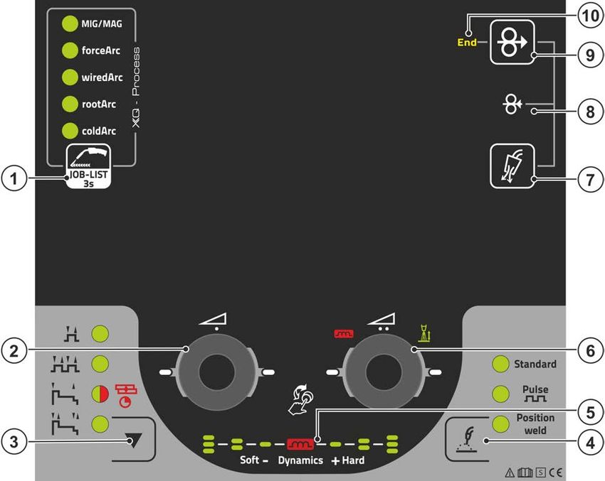
Contents
                                                                                                       Notes on using these operating instructions

1        Contents
         1 Contents .......................................................................................................................................... 3
         2 For your safety ............................................................................................................................... 6
           2.1 Notes on using these operating instructions .......................................................................... 6
           2.2 Explanation of icons ............................................................................................................... 7
           2.3 Safety instructions .................................................................................................................. 8
           2.4 Transport and installation .................................................................................................... 11
         3 Intended use ................................................................................................................................. 13
           3.1 Use and operation solely with the following machines ........................................................ 13
           3.2 Software version .................................................................................................................. 13
           3.3 Documents which also apply ............................................................................................... 13
                 3.3.1     Part of the complete documentation ..................................................................... 14
         4 Machine control – Operating elements ...................................................................................... 15
           4.1 Overview of control sections ................................................................................................ 15
                4.1.1    Control section A .................................................................................................. 16
                4.1.2    Control section B .................................................................................................. 17
                4.1.3    Control section C .................................................................................................. 18
           4.2 Welding data display ............................................................................................................ 20
           4.3 Operating the machine control ............................................................................................. 21
                4.3.1    Main screen .......................................................................................................... 21
                4.3.2    Welding power setting .......................................................................................... 21
                4.3.3    Welding parameter setting in the operation sequence ......................................... 21
                4.3.4    Setting advanced welding parameters (Expert menu) ......................................... 22
                4.3.5    Changing basic settings (machine configuration menu) ...................................... 22
                4.3.6    Lock function ........................................................................................................ 22
         5 Functional characteristics ........................................................................................................... 23
           5.1 Shielding gas volume settings ............................................................................................. 23
                5.1.1    Gas test ................................................................................................................ 23
                5.1.2    Purge hose package............................................................................................. 24
           5.2 Wire inching ......................................................................................................................... 24
           5.3 Wire return ........................................................................................................................... 25
           5.4 MIG/MAG welding ................................................................................................................ 26
                5.4.1    Welding task selection .......................................................................................... 26
                5.4.2    Basic welding parameters .................................................................................... 26
                5.4.3    Welding procedure ............................................................................................... 27
                5.4.4    Operating mode .................................................................................................... 27
                5.4.5    Welding type ......................................................................................................... 28
                5.4.6    Welding power (operating point) .......................................................................... 29
                         5.4.6.1 Accessory components for operating point setting ............................... 29
                         5.4.6.2 Arc length .............................................................................................. 30
                         5.4.6.3 Arc dynamics (choke effect) .................................................................. 30
                5.4.7    superPuls .............................................................................................................. 31
                5.4.8    Copy JOB (welding task) ...................................................................................... 32
                5.4.9    Expert menu (MIG/MAG) ...................................................................................... 33
                5.4.10 Burn-back ............................................................................................................. 34
                5.4.11 Programme limit ................................................................................................... 35
                5.4.12 Programs (PA 1-15) .............................................................................................. 35
                         5.4.12.1 Selection and adjustment ...................................................................... 36
                5.4.13 Program sequence ............................................................................................... 38
                         5.4.13.1 Selection ............................................................................................... 38
                         5.4.13.2 Setting ................................................................................................... 39
                5.4.14 Operating modes (functional sequences)............................................................. 40
                         5.4.14.1 Explanation of signs and functions ....................................................... 40
                         5.4.14.2 Automatic cut-out .................................................................................. 40
                5.4.15 forceArc / forceArc puls ........................................................................................ 53
                5.4.16 wiredArc ................................................................................................................ 54
                5.4.17 rootArc/rootArc puls .............................................................................................. 54
                5.4.18 coldArc / coldArc puls ........................................................................................... 55
                5.4.19 Standard MIG/MAG torch ..................................................................................... 55
099-00HPXQ-EW501
13.01.2022
                                                                                                                                                                   3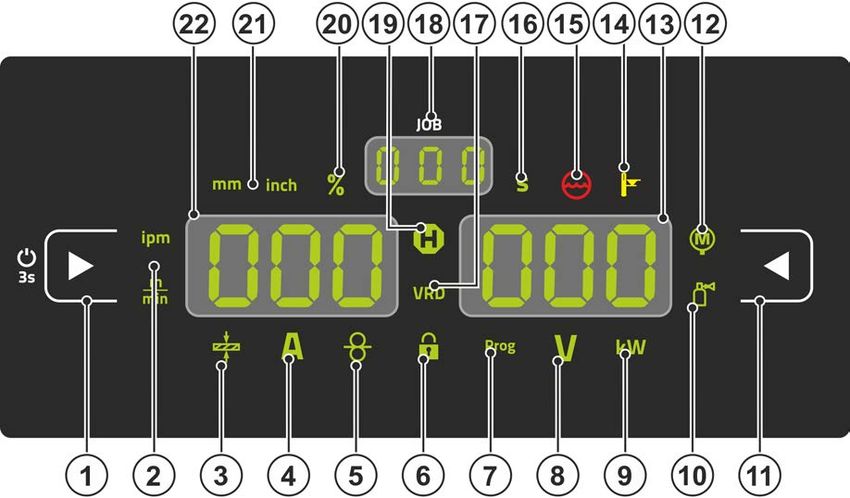
Contents
Notes on using these operating instructions

                    5.4.20
                         MIG/MAG special-torches ..................................................................................... 55
                         5.4.20.1 Program and up/down operation ........................................................... 55
                         5.4.20.2 Switching between Push/Pull and intermediate drive ........................... 56
           5.5 TIG welding .......................................................................................................................... 56
                5.5.1    Welding task selection .......................................................................................... 56
                         5.5.1.1 Welding current setting.......................................................................... 56
                5.5.2    Arc ignition ............................................................................................................ 57
                         5.5.2.1 Liftarc ..................................................................................................... 57
                5.5.3    Operating modes (functional sequences) ............................................................. 57
                         5.5.3.1 Explanation of signs and functions ........................................................ 57
                         5.5.3.2 Automatic cut-out .................................................................................. 58
           5.6 MMA welding ........................................................................................................................ 62
                5.6.1    Welding task selection .......................................................................................... 62
                         5.6.1.1 Welding current setting.......................................................................... 62
                5.6.2    Arcforce................................................................................................................. 62
                5.6.3    Hotstart ................................................................................................................. 63
                         5.6.3.1 Hotstart current ...................................................................................... 63
                         5.6.3.2 Hotstart time .......................................................................................... 63
                5.6.4    Antistick................................................................................................................. 63
           5.7 Options (additional components) ......................................................................................... 64
                5.7.1    Electronic gas flow control (OW DGC) ................................................................. 64
                5.7.2    Wire reserve sensor (OW WRS)........................................................................... 64
                5.7.3    Wire spool heater (OW WHS)............................................................................... 64
           5.8 Access control ...................................................................................................................... 64
           5.9 Voltage reducing device ....................................................................................................... 64
           5.10 Special parameters (advanced settings) .............................................................................. 64
                5.10.1 Selecting, changing and saving parameters......................................................... 65
                5.10.2 Ramp time for wire inching (P1) ........................................................................... 67
                5.10.3 Program "0", releasing the program block (P2) .................................................... 67
                5.10.4 Display mode for Up/Down welding torch with one-digit 7-segment display (P3) 67
                5.10.5 Program limit (P4) ................................................................................................. 67
                5.10.6 Special cycle in the operating modes special latched and non-latched (P5) ....... 68
                5.10.7 Correction operation, threshold value setting (P7) ............................................... 68
                5.10.8 Switching programs with the standard torch trigger (P8) ..................................... 70
                5.10.9 Latched/special-latched tap start (P9) .................................................................. 71
                5.10.10 "Single or dual operation" (P10) setting ................................................................ 71
                5.10.11 Latched special tapping time setting (P11) ........................................................... 71
                5.10.12 JOB list switching (P12) ........................................................................................ 72
                5.10.13 Lower and upper limits of the remote JOB changeover process (P13, P14) ....... 72
                5.10.14 Hold function (P15) ............................................................................................... 72
                5.10.15 Block JOB mode (P16) ......................................................................................... 73
                5.10.16 Selecting programs with the standard torch trigger (P17) .................................... 73
                5.10.17 Mean value display for superPuls (P19) ............................................................... 73
                5.10.18 Predefined execution of the pulsed arc welding process in the PA program (P20)
                          .............................................................................................................................. 74
                5.10.19 Predefined absolute value for relative programs (P21) ........................................ 74
                5.10.20 Electronic gas flow control, type (P22) ................................................................. 74
                5.10.21 Program settings for relative programs (P23) ....................................................... 74
                5.10.22 Correction or nominal voltage display (P24) ......................................................... 74
                5.10.23 JOB selection in Expert mode (P25) .................................................................... 74
                5.10.24 Nominal value wire heater (P26) .......................................................................... 74
                5.10.25 Mode switching at welding start (P27) .................................................................. 74
                5.10.26 Error threshold electronic gas flow control (P28) ................................................. 74
                5.10.27 Units system (P29) ............................................................................................... 74
                5.10.28 Selection option – Program sequence with welding power rotary knob (P30) ..... 75
                5.10.29 Reset to factory settings ....................................................................................... 75
           5.11 Machine configuration menu ................................................................................................ 76
                5.11.1 Selecting, changing and saving parameters......................................................... 76
                5.11.2 Aligning the cable resistance ................................................................................ 77
           5.12 Power-saving mode (Standby) ............................................................................................. 78

4                                                                                                                               099-00HPXQ-EW501
                                                                                                                                                  13.01.2022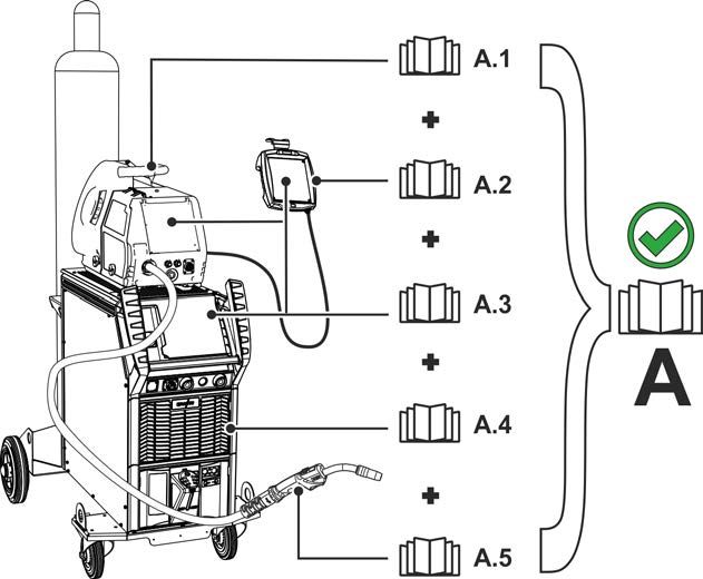
Contents
                                                                                                      Notes on using these operating instructions

         6 Maintenance, care and disposal ................................................................................................. 79
           6.1 General ................................................................................................................................ 79
           6.2 Disposing of equipment ....................................................................................................... 80
         7 Rectifying faults ........................................................................................................................... 81
           7.1 Display machine control software version ........................................................................... 81
           7.2 Error messages (power source) .......................................................................................... 81
           7.3 Warnings .............................................................................................................................. 84
           7.4 Resetting JOBs (welding tasks) to the factory settings ....................................................... 86
                 7.4.1     Resetting a single JOB ......................................................................................... 86
                 7.4.2     Resetting all JOBs ................................................................................................ 86
         8 Appendix ....................................................................................................................................... 87
           8.1 JOB-List ............................................................................................................................... 87
           8.2 Parameter overview – setting ranges .................................................................................. 94
                8.2.1        MIG/MAG welding ................................................................................................ 94
                8.2.2        TIG welding .......................................................................................................... 95
                8.2.3        MMA welding ........................................................................................................ 95
           8.3 Searching for a dealer.......................................................................................................... 96

099-00HPXQ-EW501
13.01.2022
                                                                                                                                                                 5
For your safety
Notes on using these operating instructions

2       For your safety
2.1     Notes on using these operating instructions
                                                                DANGER
                    Working or operating procedures which must be closely observed to prevent imminent
                    serious and even fatal injuries.
                    • Safety notes include the "DANGER" keyword in the heading with a general warning symbol.
                    • The hazard is also highlighted using a symbol on the edge of the page.

                                                               WARNING
                    Working or operating procedures which must be closely observed to prevent serious
                    and even fatal injuries.
                    • Safety notes include the "WARNING" keyword in the heading with a general warning sym-
                      bol.
                    • The hazard is also highlighted using a symbol in the page margin.

                                                               CAUTION
                    Working or operating procedures which must be closely observed to prevent possible
                    minor personal injury.
                    • The safety information includes the "CAUTION" keyword in its heading with a general warn-
                      ing symbol.
                    • The risk is explained using a symbol on the edge of the page.

            Technical aspects which the user must observe to avoid material or equipment damage.
        Instructions and lists detailing step-by-step actions for given situations can be recognised via bullet
        points, e.g.:
        •    Insert the welding current lead socket into the relevant socket and lock.

6                                                                                             099-00HPXQ-EW501
                                                                                                           13.01.2022
For your safety
                                                                                                Explanation of icons

2.2      Explanation of icons
             Symbol   Description                                 Symbol Description

                      Indicates technical aspects which the u-           Activate and release / Tap / Tip
                      ser must observe.

                      Switch off machine                                 Release

                      Switch on machine                                  Press and hold

                                                                         Switch

                      Incorrect / Invalid                                Turn

                      Correct / Valid                                    Numerical value – adjustable

                      Input                                              Signal light lights up in green

                      Navigation                                         Signal light flashes green

                      Output                                             Signal light lights up in red

                      Time representation (e.g.: wait 4 s / ac-          Signal light flashes red
                      tuate)

                      Interruption in the menu display (other
                      setting options possible)

                      Tool not required/do not use

                      Tool required/use

099-00HPXQ-EW501
13.01.2022
                                                                                                               7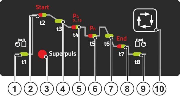
For your safety
Safety instructions

2.3     Safety instructions
                                                            WARNING
                   Risk of accidents due to non-compliance with the safety instructions!
                   Non-compliance with the safety instructions can be fatal!
                   • Carefully read the safety instructions in this manual!
                   • Observe the accident prevention regulations and any regional regulations!
                   • Inform persons in the working area that they must comply with the regulations!
                  Risk of injury from electrical voltage!
                  Voltages can cause potentially fatal electric shocks and burns on contact. Even low vol-
                  tages can cause a shock and lead to accidents.
                  • Never touch live components such as welding current sockets or stick, tungsten or wire
                      electrodes!
                  • Always place torches and electrode holders on an insulated surface!
                  • Wear the full personal protective equipment (depending on the application)!
                  • The machine may only be opened by qualified personnel!
                  • The device must not be used to defrost pipes!
                   Hazard when interconnecting multiple power sources!
                   If a number of power sources are to be connected in parallel or in series, only a techni-
                   cal specialist may interconnect the sources as per standard IEC 60974-9:2010: Installa-
                   tion and use and German Accident Prevention Regulation BVG D1 (formerly VBG 15) or
                   country-specific regulations.
                   Before commencing arc welding, a test must verify that the equipment cannot exceed
                   the maximum permitted open circuit voltage.
                   • Only qualified personnel may connect the machine.
                   • When taking individual power sources out of operation, all mains and welding current leads
                       must be safely disconnected from the welding system as a whole. (Hazard due to reverse
                       polarity voltage!)
                   • Do not interconnect welding machines with pole reversing switch (PWS series) or machines
                       for AC welding since a minor error in operation can cause the welding voltages to be com-
                       bined, which is not permitted.
                   Risk of injury due to radiation or heat!
                   Arc radiation can lead to skin and eye injuries.
                   Contact with hot workpieces and sparks can lead to burns.
                   • Use hand shield or welding helmet with the appropriate safety level (depends on the appli-
                       cation).
                   • Wear dry protective clothing (e.g. hand shield, gloves, etc.) in accordance with
                       the applicable regulations of your country.
                   • Persons who are not directly involved should be protected with a welding curtain or suitable
                       safety screen against radiation and the risk of blinding!

8                                                                                         099-00HPXQ-EW501
                                                                                                       13.01.2022
For your safety
Safety instructions
WARNING
Risk of injury due to improper clothing!
During arc welding, radiation, heat and voltage are sources of risk that cannot be
avoided. The user has to be equipped with the complete personal protective equipment
at all times. The protective equipment has to include:
• Respiratory protection against hazardous substances and mixtures (fumes and vapours);
otherwise implement suitable measures such as extraction facilities.
• Welding helmet with proper protection against ionizing radiation (IR and UV radiation) and
heat.
• Dry welding clothing (shoes, gloves and body protection) to protect against warm environ-
ments with conditions comparable to ambient temperatures of 100 °C or higher and arcing
and work on live components.
• Hearing protection against harming noise.
Explosion risk!
Apparently harmless substances in closed containers may generate excessive pressure
when heated.
• Move containers with inflammable or explosive liquids away from the working area!
• Never heat explosive liquids, dusts or gases by welding or cutting!
Fire hazard!
Due to the high temperatures, sparks, glowing parts and hot slag that occur during
welding, there is a risk of flames.
• Be watchful of potential sources of fire in the working area!
• Do not carry any easily inflammable objects, e.g. matches or lighters.
• Ensure suitable fire extinguishers are available in the working area!
• Thoroughly remove any residue of flammable materials from the workpiece prior to starting
to weld.
• Only further process workpieces after they have cooled down. Do not allow them to contact
any flammable materials!
099-00HPXQ-EW501
13.01.2022
9For your safety
Safety instructions
CAUTION
Smoke and gases!
Smoke and gases can lead to breathing difficulties and poisoning. In addition, solvent
vapour (chlorinated hydrocarbon) may be converted into poisonous phosgene due to
the ultraviolet radiation of the arc!
• Ensure that there is sufficient fresh air!
• Keep solvent vapour away from the arc beam field!
• Wear suitable breathing apparatus if appropriate!
Noise exposure!
Noise exceeding 70 dBA can cause permanent hearing damage!
• Wear suitable ear protection!
• Persons located within the working area must wear suitable ear protection!
According to IEC 60974-10, welding machines are divided into two classes of
electromagnetic compatibility (the EMC class can be found in the Technical data):
Class A machines are not intended for use in residential areas where the power supply comes
from the low-voltage public mains network. When ensuring the electromagnetic compatibility of
class A machines, difficulties can arise in these areas due to interference not only in the supply
lines but also in the form of radiated interference.
Class B machines fulfil the EMC requirements in industrial as well as residential areas, inclu-
ding residential areas connected to the low-voltage public mains network.
Setting up and operating
When operating arc welding systems, in some cases, electro-magnetic interference can occur
although all of the welding machines comply with the emission limits specified in the standard.
The user is responsible for any interference caused by welding.
In order to evaluate any possible problems with electromagnetic compatibility in the
surrounding area, the user must consider the following: (see also EN 60974-10 Appendix A)
• Mains, control, signal and telecommunication lines
• Radios and televisions
• Computers and other control systems
• Safety equipment
• The health of neighbouring persons, especially if they have a pacemaker or wear a hearing
aid
• Calibration and measuring equipment
• The immunity to interference of other equipment in the surrounding area
• The time of day at which the welding work must be carried out
Recommendations for reducing interference emission
• Mains connection, e.g. additional mains filter or shielding with a metal tube
• Maintenance of the arc welding system
• Welding leads should be as short as possible and run closely together along the ground
• Potential equalization
• Earthing of the workpiece. In cases where it is not possible to earth the workpiece directly,
it should be connected by means of suitable capacitors.
• Shielding from other equipment in the surrounding area or the entire welding system
Electromagnetic fields!
The power source may cause electrical or electromagnetic fields to be produced which
could affect the correct functioning of electronic equipment such as IT or CNC devices,
telecommunication lines, power cables, signal lines and pacemakers.
• Observe the maintenance instructions!
• Unwind welding leads completely!
• Shield devices or equipment sensitive to radiation accordingly!
• The correct functioning of pacemakers may be affected (obtain advice from a doctor if nec-
essary).
10 099-00HPXQ-EW501
13.01.2022For your safety
Transport and installation
CAUTION
Obligations of the operator!
The respective national directives and laws must be complied with when operating the
machine!
• Implementation of national legislation relating to framework directive 89/391/EEC on the int-
roduction of measures to encourage improvements in the safety and health of workers at
work and associated individual guidelines.
• In particular, directive 89/655/EEC concerning the minimum safety and health requirements
for the use of work equipment by workers at work.
• The regulations applicable to occupational safety and accident prevention in the country
concerned.
• Setting up and operating the machine as per IEC 60974.-9.
• Brief the user on safety-conscious work practices on a regular basis.
• Regularly inspect the machine as per IEC 60974.-4.
The manufacturer's warranty becomes void if non-genuine parts are used!
• Only use system components and options (power sources, welding torches, electrode hold-
ers, remote controls, spare parts and replacement parts, etc.) from our range of products!
• Only insert and lock accessory components into the relevant connection socket when the ma-
chine is switched off.
Requirements for connection to the public mains network
High-performance machines can influence the mains quality by taking current from the mains
network. For some types of machines, connection restrictions or requirements relating to the
maximum possible line impedance or the necessary minimum supply capacity at the interface
with the public network (Point of Common Coupling, PCC) can therefore apply. In this respect,
attention is also drawn to the machines' technical data. In this case, it is the responsibility of the
operator, where necessary in consultation with the mains network operator, to ensure that the
machine can be connected.
2.4 Transport and installation
WARNING
Risk of injury due to improper handling of shielding gas cylinders!
Improper handling and insufficient securing of shielding gas cylinders can cause seri-
ous injuries!
• Observe the instructions from the gas manufacturer and any relevant regulations concern-
ing the use of compressed air!
• Do not attach any element to the shielding gas cylinder valve!
• Prevent the shielding gas cylinder from heating up.
099-00HPXQ-EW501
13.01.2022
11For your safety
Transport and installation
CAUTION
Risk of accidents due to supply lines!
During transport, attached supply lines (mains leads, control cables, etc.) can cause
risks, e.g. by causing connected machines to tip over and injure persons!
• Disconnect all supply lines before transport!
Risk of tipping!
There is a risk of the machine tipping over and injuring persons or being damaged itself
during movement and set up. Tilt resistance is guaranteed up to an angle of 10° (ac-
cording to IEC 60974-1).
• Set up and transport the machine on level, solid ground.
• Secure add-on parts using suitable equipment.
Risk of accidents due to incorrectly installed leads!
Incorrectly installed leads (mains, control and welding leads or intermediate hose pack-
ages ) can present a tripping hazard.
• Lay the supply lines flat on the floor (avoid loops).
• Avoid laying the leads on passage ways.
Risk of injury from heated coolant and its connections!
The coolant used and its connection or connection points can heat up significantly
during operation (water-cooled version). When opening the coolant circuit, escaping
coolant may cause scalding.
• Open the coolant circuit only when the power source or cooling unit is switched off!
• Wear proper protective equipment (protective gloves)!
• Seal open connections of the hose leads with suitable plugs.
The units are designed for operation in an upright position!
Operation in non-permissible positions can cause equipment damage.
• Only transport and operate in an upright position!
Accessory components and the power source itself can be damaged by incorrect connection!
• Only insert and lock accessory components into the relevant connection socket when the
machine is switched off.
• Comprehensive descriptions can be found in the operating instructions for the relevant ac-
cessory components.
• Accessory components are detected automatically after the power source is switched on.
Protective dust caps protect the connection sockets and therefore the machine against dirt and
damage.
• The protective dust cap must be fitted if there is no accessory component being operated on
that connection.
• The cap must be replaced if faulty or if lost!
12 099-00HPXQ-EW501
13.01.2022Intended use
Use and operation solely with the following machines
3 Intended use
WARNING
Hazards due to improper usage!
The machine has been constructed to the state of the art and any regulations and stand-
ards applicable for use in industry and trade. It may only be used for the welding proce-
dures indicated at the rating plate. Hazards may arise for persons, animals and material
objects if the equipment is not used correctly. No liability is accepted for any damages
arising from improper usage!
• The equipment must only be used in line with its designated purpose and by trained or
expert personnel!
• Do not improperly modify or convert the equipment!
3.1 Use and operation solely with the following machines
This description may only be applied to machines with the M3.7X-I machine control.
3.2 Software version
These instructions apply to the following software version:
1.0.D.0
The software version of the machine control can be displayed in the machine configuration menu
(menu Srv) > see 5.11 chapter.
3.3 Documents which also apply
• Operating instructions for the connected welding machines
• Documents of the optional expansions
099-00HPXQ-EW501
13.01.2022
13Intended use
Documents which also apply
3.3.1 Part of the complete documentation
This document is part of the complete documentation and valid only in combination with all other
parts of these instructions! Read and observe the operating instructions for all system
components, especially the safety instructions!
The illustration shows a general example of a welding system.
Figure 3-1
The illustration shows a general example of a welding system.
Item Documentation
A.1 Wire feeder
A.2 Remote adjuster
A.3 Controller
A.4 Power source
A.5 Welding torch
A Complete documentation
14 099-00HPXQ-EW501
13.01.2022Machine control – Operating elements
Overview of control sections
4 Machine control – Operating elements
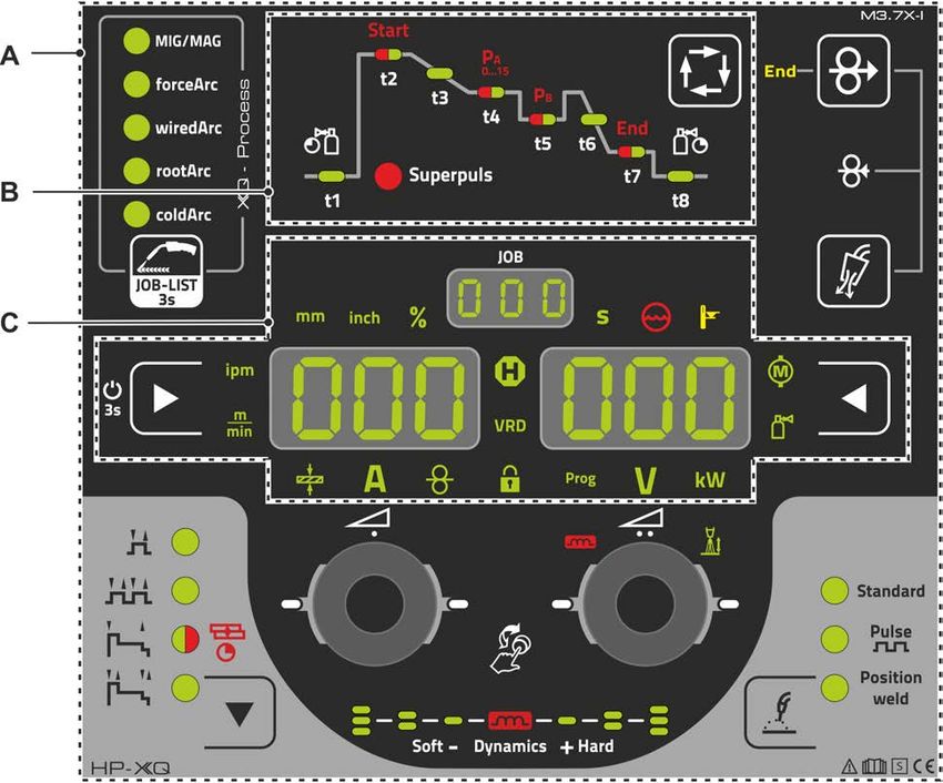
4.1 Overview of control sections
For description purposes, the machine control has been divided into three sections (A, B, C) to
ensure maximum clarity. The setting range for the parameter values are summarised in the
parameter overview section > see 8.2 chapter.
Figure 4-1
Item Symbol Description 0
1 Control section A
> see 4.1.1 chapter
2 Control section B
> see 4.1.2 chapter
3 Control section C
> see 4.1.3 chapter
099-00HPXQ-EW501
13.01.2022
15Machine control – Operating elements
Overview of control sections
4.1.1 Control section A
Figure 4-2
Item Symbol Description 0
1 Welding task push-button (JOB)
• ---------- Pressing the pushbutton briefly: Fast switching of the available welding proce-
dures in the selected basic parameters (material/wire/gas).
• ---------- Pressing the pushbutton longer: Select the welding task (JOB) from the
welding task list (JOB-LIST) > see 5.4.1 chapter.
2 Rotary knob (click wheel ) for welding power
• ---------- Setting the welding power > see 5.4.6 chapter
• ---------- Setting various parameters values depending on the preselection.
(Settings can be made when the backlight is activated.)
3 Operating modes push-button (functional sequences) > see 5.4.14 chapter
-------- Non-latched
------ Latched
-------- Signal light turns green: Special non-latched
---- Signal light turns red: MIG spots
-------- Special latched
4 Welding type push-button > see 5.4.5 chapter
5 Display of arc dynamics
The height and orientation of the set arc dynamics are displayed.
16 099-00HPXQ-EW501
13.01.2022Machine control – Operating elements
Overview of control sections
Item Symbol Description 0
6 Correction of arc length with click wheel
• ----------- Setting the correction of arc length > see 5.4.6.2 chapter
• ----------- Setting the arc dynamics > see 5.4.6.3 chapter
• ----------- Setting various parameter values depending on the preselection.
Settings can be made when the backlight is activated.
7 Push-button gas test / rinse hose package > see 5.1 chapter
8 Wire return > see 5.3 chapter
Potential and gas-free return of the wire electrode.
9 Wire inching push-button
Potential and gas-free inching of the wire electrode > see 5.2 chapter.
10 End Signal light wire reserve sensor (ex works option) > see 5.7.2 chapter
Lights up when the welding wire is less than approx. 10% residual quantity.
4.1.2 Control section B
Figure 4-3
Item Symbol Description 0
1 t1 Gas pre-flow time signal light
2 t2 Start program signal light Start
--------- Welding power (percent of main program PA)
-------- Arc length correction
--------- Start time "t1"
Start and end programs are only active in 2- and 4-cycle-special modes.
3 Super- Signal lamp, superPuls function
puls Lights up when the superPuls function is active.
4 t3 Slope time "tS1" signal light
Slope time from program Start on main program PA
5 t4 Main program signal light (PA)
--------- Welding power (wire feed speed/welding current/material thickness)
--------- Arc length correction
--------- Main program duration "t2" (Superpuls)
6 t5 Reduced main program signal light (PB)
--------- Wire feed speed (percent of main program PA)
--------- Arc length correction
--------- Down-slope program duration "t3" (Superpuls)
7 t6 Slope time "tSE" signal light
Slope time from main program Start to end program End
099-00HPXQ-EW501
13.01.2022
17Machine control – Operating elements
Overview of control sections
Item Symbol Description 0
8 t7 End program signal light End
--------- Wire feed speed (percent of main program PA)
--------Arc length correction
--------- End current time "t10"
Start and end programs are only active in the 2- and 4-cycle Special modes.
9 t8 Gas post-flow time signal light
10 Select welding parameters button
This button is used to select the welding parameters depending on the welding process
and operating mode used.
4.1.3 Control section C
Figure 4-4
Item Symbol Description 0
1 Display left / Lock function push-button
Switching the device display between various welding parameters. Signal lamps show
the selected parameter.
-------- Press for 3 s to put the machine into lock function > see 4.3.6 chapter.
2 Wire feed speed unit signal light
m/min --- Parameter value is displayed in meters per minute.
ipm ------- Parameter value is displayed in inches per minute.
Switching between metric or imperial system via special parameters
"P29" > see 5.10 chapter.
3 Material thickness signal light
Indication of the selected material thickness.
4 Welding current signal light
Display of the welding current in amperes.
5 Signal light, Wire speed
Lights when the wire speed is shown on the display.
6 Lock function signal light
Use display left / lock function push-button to switch on and off.
7 Signal light for the welding program > see 5.4.12 chapter
Display of the current program number in the welding data display.
18 099-00HPXQ-EW501
13.01.2022Machine control – Operating elements
Overview of control sections
Item Symbol Description 0
8 Correction voltage arc length signal light
Display of correction voltage arc length in volts.
9 Welding power signal light
Display of welding power in kilowatts.
10 Electronic gas flow control signal light OW DGC > see 5.7.1 chapter
Shows the gas flow rate in the device display.
11 Display push-button, right
Primary display of arc length correction and other parameters and their values.
12 Motor current signal light
During wire inching, the current motor current (wire feed mechanism) is displayed in
amperes.
13 Display right - Primary display of welding voltage
This display shows the welding voltage, arc length correction, programs or welding
power (switching by Display right push-button). Furthermore, dynamics and, depending
on the preselection, various welding parameter valuesare displayed. Parameter times
or hold values > see 4.2 chapter.
14 Excess temperature signal light / Welding torch cooling failure
For error messages > see 7 chapter
15 Coolant fault signal light
Indicates flow fault or low coolant level.
16 Second signal light
The displayed value is displayed in seconds.
17 VRD Voltage reduction device (VRD) signal light > see 5.9 chapter
18 JOB number display (welding task) > see 5.4.1 chapter
19 Status display signal light (Hold)
Display of mean values across the entire welding process.
20 Percent signal light
The displayed value is displayed in percent.
21 Material thickness unit signal light
mm ------- Parameter value is displayed in millimeters.
inch ------ Parameter value is displayed in inches.
Switching between metric or imperial system via special parameters
"P29" > see 5.10 chapter.
22 Display left - Primary display of welding power
This display shows the welding power either as wire feed speed, welding current or ma-
terial thickness (switching by display push-button on the left). Furthermore, depending
on the preselection, various welding parameter valuesare displayed. Parameter times
or hold values > see 4.2 chapter.
099-00HPXQ-EW501
13.01.2022
19Machine control – Operating elements
Welding data display
4.2 Welding data display
On the left and right of the parameter displays there are push-buttons for the selection of parameters.
They are used to select the welding parameters to be displayed and their values.
Each time one the button is clicked, the display proceeds to the next parameter (signal lights indicate the
selection). After reaching the last parameter, the system is restarted with the first one.
Figure 4-5
MIG/MAG
Parameter Nominal values [1] Actual values [2] Hold values [3]
Welding current
Material thickness
Wire feed speed
Welding voltage
Welding power
Motor current
Shielding gas
TIG
Parameter Nominal values [1] Actual values [2] Hold values [3]
Welding current
Welding voltage
Welding power
Shielding gas
MMA
Parameter Nominal values [1] Actual values [2] Hold values [3]
Welding current
Welding voltage
Welding power
When settings are changed (e.g. wire feed speed) the display immediately switches to nominal value set-
ting.
[1] Nominal values (before welding)
[2] Actual values (during welding)
[3] Hold values (after welding, display of mean values across entire welding process)
20 099-00HPXQ-EW501
13.01.2022Machine control – Operating elements
Operating the machine control
4.3 Operating the machine control
4.3.1 Main screen
The machine control switches to the main screen after it has been turned on or a setting has been com-
pleted. This means that the previously selected settings (indicated by signal lights where applicable) and
the nominal value for the current (A) are displayed in the left-hand welding data display. Depending on
the selection, the right-hand display shows the welding voltage (V) nominal value or the welding power
(kW) actual value. The control always switches back to the main screen after 4 sec..
4.3.2 Welding power setting
The welding power is adjusted with the rotary knob (click wheel) for welding power. You can also adjust
the parameters in the operation sequence or settings in the various machine menus.
MIG/MAG settings
The welding power (heat input into the material) can be changed by setting the following three parame-
ters:
• wire feed speed
• material thickness
• welding current A
These three parameters are interdependent and always change together. The significant parameter is the
wire feed speed in m/min. The wire feed speed can be adjusted in increments of 0.1 m/min (4.0 ipm). The
associated welding current and material thickness are determined from the wire feed speed.
The welding current displayed and material thickness are to be understood as guide values for the user
and rounded to full amperage and 0.1 mm material thickness.
A change in the wire feed speed, for example by 0.1 m/min, leads to a more or less large change in the
welding current displayed or in the material thickness displayed depending on the selected welding wire
diameter. The display of the welding current and the material thickness are also dependent on the selec-
ted wire diameter.
For example, a change in wire feed speed of 0.1 m/min and a selected wire diameter of 0.8 mm results in
a smaller change in the current or thickness of material than a change in wire feed speed of 0.1 m/min
and a selected wire diameter of 1.6 mm.
Depending on the diameter of the wire to be welded, it is possible that smaller or larger jumps in the dis-
play of material thickness or welding current take place or changes of these values become visible only
after several “clicks” on the rotary transducer. As described above, the reason for this is the change in the
wire feed speed by 0.1 m/min per click and the resulting change in the current or material thickness as a
function of the preselected welding wire diameter.
Please note also that the guide value of the welding current displayed before welding may deviate from
the guide value during welding depending on the actual stick-out (free wire end used for welding).
The reason lies in the preheating of the free wire end by the welding current. For example, the preheating
in the welding wire increases with the length of the stick-out. This means if the stick-out (free wire end)
increases, the actual welding current decreases due to larger preheating in the wire. If the free wire end
decreases, the actual welding current increases. This enables the welder to influence the heat input in the
component within limits by changing the distance of the welding torch.
Setting of TIG/MMA:
The welding power is set with the parameter “welding current” that can be adjusted in increments of 1 am-
pere.
4.3.3 Welding parameter setting in the operation sequence
A welding parameter can be set in two ways in the operation sequence.
1. Pressing the welding parameter push-button (a flashing signal light indicates the selected parameter).
The parameter setting is carried out by the welding power click wheel.
2. Press briefly on the welding power click wheel (operation sequence selection) and then turn the button
(navigate to the required parameter). Press again to apply the selected parameter as the setting (cor-
responding parameter value and signal light flash). Turn the button to set the parameter value.
099-00HPXQ-EW501
13.01.2022
21Machine control – Operating elements
Operating the machine control
4.3.4 Setting advanced welding parameters (Expert menu)
The Expert menu contains functions and parameters which cannot be set directly in the machine control
or which do not need to be et on a regular basis. The number and display of these parameters depends
on the previously selected welding procedure or the functions. To select them hold the welding power
click wheel (> 2 s). Select the required parameter/menu item by turning (navigating) and pressing the
click wheel. Additionally or alternatively, you can use the welding parameters push-button for navigation.
4.3.5 Changing basic settings (machine configuration menu)
The basic welding system functions can be adjusted in the machine configuration menu. Only experi-
enced users should change the settings > see 5.11 chapter.
4.3.6 Lock function
The lock function protects against accidental adjustment of the device settings.
The user can switch the lock function on or off by pressing the button for a long time from each machine
control or accessory component with the symbol .
22 099-00HPXQ-EW501
13.01.2022Functional characteristics
Shielding gas volume settings
5 Functional characteristics
5.1 Shielding gas volume settings
If the shielding gas setting is too low or too high, this can introduce air to the weld pool and may cause
pores to form. Adjust the shielding gas quantity to suit the welding task!
• Slowly open the gas cylinder valve.
• Open the pressure regulator.
• Switch on the power source at the main switch.
• Trigger gas test > see 5.1.1 chapter function (welding voltage and wire feed motor remain switched off
– no accidental arc ignition).
• Set the relevant gas quantity for the application on the pressure regulator.
Setting instructions
Welding process Recommended shielding gas quantity
MAG welding Wire diameter x 11.5 = l/min
MIG brazing Wire diameter x 11.5 = l/min
MIG welding (aluminium) Wire diameter x 13.5 = l/min (100 % argon)
TIG Gas nozzle diameter in mm corresponds to l/min gas throughput
Helium-rich gas mixtures require a higher gas volume!
The table below can be used to correct the gas volume calculated where necessary:
Shielding gas Factor
75% Ar/25% He 1.14
50% Ar/50% He 1.35
25% Ar/75% He 1.75
100% He 3.16
5.1.1 Gas test
25s
0
Figure 5-1
099-00HPXQ-EW501
13.01.2022
23Functional characteristics
Wire inching
5.1.2 Purge hose package
300s
0
5s
Figure 5-2
5.2 Wire inching
The wire inching function is used for potential- and gas-free inching of the wire electrode after the wire
spool change. By pressing and holding the wire inching button for a long time, the wire inching speed in-
creases in a ramp function (special parameter P1 > see 5.10.2 chapter) from 1 m/min to the set maximum
value. The maximum value is set by simultaneously pressing the wire inching button and turning the left
click wheel.
Figure 5-3
24 099-00HPXQ-EW501
13.01.2022Functional characteristics
Wire return
5.3 Wire return
The wire return function is used to retract the wire electrode without tension and protection gas. By simul-
taneously pressing and holding the wire inching and gas test buttons, the wire return speed increases in a
ramp function (special parameter P1 > see 5.10.2 chapter) from 1 m/min to the set maximum value. The
maximum value is set by simultaneously pressing the wire inching button and turning the left click wheel.
During the process, the wire spool must be turned by hand clockwise to wind up the wire electrode again.
+
Figure 5-4
099-00HPXQ-EW501
13.01.2022
25Functional characteristics
MIG/MAG welding
5.4 MIG/MAG welding
5.4.1 Welding task selection
The following steps have to be carried out to select the welding job:
• Select basic parameters (material type, wire diameter and shielding gas type) and welding procedures
(select and enter JOB number by means of JOB-List > see 8.1 chapter).
• Select operating and welding type
• Adjust welding power
• Correct arc length and dynamics if necessary
• Adjust expert parameters for special applications
5.4.2 Basic welding parameters
The user must first determine the basic parameters (material type, wire diameter and shielding gas type)
of the welding system. These basic parameters are then compared with the welding job list (JOB-LIST).
The combination of the basic parameters gives a JOB number, which must now be entered on the control
unit. This basic setting must be rechecked or adjusted only when changing the wire or gas.
The range of functions depends on the machine series:
Machine series MIG/MAG XQ forceArc XQ wiredArc XQ rootArc XQ coldArc XQ
Titan XQ
Phoenix XQ
Taurus XQ
JOB-LIST
Figure 5-5
26 099-00HPXQ-EW501
13.01.2022Functional characteristics
MIG/MAG welding
5.4.3 Welding procedure
After setting the basic parameters you can switch between the welding procedures MIG/MAG, forceArc,
wiredArc, rootArc und coldArc (if there is a corresponding combination of the basic parameters). The pro-
cess change will also change the JOB number, but the basic parameters remain unchanged.
Figure 5-6
5.4.4 Operating mode
The operating mode determines the process sequence controlled by the welding torch. Detailed descripti-
ons of the operating modes > see 5.4.14 chapter.
Figure 5-7
099-00HPXQ-EW501
13.01.2022
27Functional characteristics
MIG/MAG welding
5.4.5 Welding type
Different forms of MIG/MAG processes are referred to as welding type.
Standard (Welding with standard arc)
Depending on the set combination of wire feed speed and arc voltage, the arc types short arc, transitional
arc or spray arc can be used for welding.
Pulse (Welding with pulsed arc)
A targeted change in the welding current generates current pulses in the arc, which lead to a 1 drop per
pulse of material transfer. The result is an almost spatter-free process, suitable for welding of all materi-
als, in particular high-alloy CrNi steels or aluminium.
Positionweld (Positional welding)
A combination of the pulse/standard or pulse/pulse welding types, which is particularly suitable for positio-
nal welding due to factory-optimized parameters.
The range of functions depends on the machine series:
Machine series Standard Pulse Positionweld
Titan XQ
Phoenix XQ [1]
Taurus XQ
[1] Aluminium welding
Figure 5-8
28 099-00HPXQ-EW501
13.01.2022Functional characteristics
MIG/MAG welding
5.4.6 Welding power (operating point)
The welding power is adjusted according to the principle of one-knob operation. The user can set their
operating point optionally as wire feed speed, welding current or material thickness. The optimum welding
voltage for the operating point is calculated and set by the welding machine. If necessary, the user can
correct this welding voltage > see 5.4.6.2 chapter.
Figure 5-9
Application example (setting via material thickness)
The required wire feed speed is not known and is to be determined.
• Select welding task JOB 76( > see 5.4.1 chapter): material = AlMg, gas = Ar 100%, wire diameter =
1.2 mm.
• Switch the display to material thickness.
• Measure the material thickness (workpiece).
• Set the measured value, e.g. 5 mm, at the machine control.
This set value corresponds to a specific wire feed speed. Switching the display to this parameter will
show the associated value.
In this example, a material thickness of 5 mm corresponds to a wire feed speed of 8.4 m/min.
The material thickness details in the welding programs generally refer to fillet welds in the PB welding po-
sition. They should be regarded as guideline values and may differ in other welding positions.
5.4.6.1 Accessory components for operating point setting
The operating point can be set at various accessory components as well, such as remote control, special
welding torches or robot and industrial bus interfaces (optional interface for automated welding required,
not available for all machines of this series).
See the operating instructions for the machine in question for a more detailed description of the individual
machines and their functions.
099-00HPXQ-EW501
13.01.2022
29You can also read