Evolution of FML Fatigue & Damage Tolerance Assessment: Moving from Damage Tolerant Metal to Hybrid Composite
←
→
Page content transcription
If your browser does not render page correctly, please read the page content below
Evolution of FML Fatigue & Damage Tolerance Assessment:
     Moving from Damage Tolerant Metal to Hybrid Composite

                     René Alderliesten, Calvin D. Rans, Rinze Benedictus
               Faculty of Aerospace Engineering, Delft University of Technology
                                        Kluyverweg 1
                                        2629 HS Delft

                                         ABSTRACT
This paper provides an overview of the evolution of methodologies to assess fatigue and damage
tolerance of hybrid laminated structures. The transition from metallic methodologies towards full
hybrid methodologies is evaluated and discussed. The transition is illustrated with the assessment
of fatigue initiation and damage growth in FMLs. In addition, the importance of structural details
for reliable assessment is explained and the necessity to explore the design freedom with the
composite FML concept is highlighted.

                                   1. INTRODUCTION
In the past decades, the Fibre Metal Laminate (FML) material concept has been developed with
success for aeronautical applications. Although originally aiming for lower wing skin panels
with FMLs containing aramid fibers (Arall), the concept has been brought to a technology
readiness level for fuselage skin applications with FMLs containing glass fibers (Glare). Today,
the interest for FML wing concepts seems to be rising again for both civil and military transport
aircraft.

In the literature, both scientific and applied research have been published on the FML
technology. Based on these publications, it can be illustrated how the assessment methodologies
evolve from metallic towards hybrid concepts. In addition, it also has been observed that lack of
interaction between science and application seems to contribute to misperceptions on the hybrid
technology at both sides. These misperceptions do not only play a role in the development of
FML concepts, but also in the related fatigue and damage tolerance assessment methodologies.

This paper provides a brief overview of the evolution of assessment methodologies for FMLs,
starting from metallic methods towards hybrid methods. The presented methodologies will be
discussed in context of lower wing skin applications.

                      2. HISTORY OF FML DEVELOPMENT
The history of the development of FMLs has been described in detail by Vlot [1] and Vogelesang
[2]. Originating from the poor man’s solution to build up aluminum structures using bonding
technology, rather than using expensive milling equipment, the major driver in the development
of FMLs has been to develop a material concept that has inherently higher resistance to (fatigue)
cracking. Here, one must realize that after the introduction of the damage tolerant design
philosophy, not only the initiation of cracks was considered, but also the subsequent propagation.
High fatigue crack growth resistance results in slow crack growth and thus increased inspection
intervals, while high fracture toughness increases the critical crack length, further increasing the
damage tolerance of structures.
The first patented FML concept combined aramid fibers with aluminum sheet materials, initially
developed for a F27 wing skin application. This concept has been thoroughly investigated
especially with respect to its fatigue characteristics [3]. Further studying the concept for wing
load spectra, however, revealed poor fatigue resistance as result of fiber failure induced during
compressive load cycles. Subsequent development led to the FML based on glass fibers, Glare
[4].
In the development of Glare, additional beneficial properties were identified that supported its
application to primary fuselages structures; high impact resistance and tolerance, high burn
through resistance which could potentially increase evacuation time (safety aspect), and
improved corrosion resistance (durability aspect) as result of its layered structure.
As a consequence, not only were structural applications which benefited from the improved
fatigue performance studied, such as wing and fuselage panels, but other applications that could
benefit from the impact and fire resistance were also studied, such as (bulk) cargo floors and
liners, flap skins, and unpressurized bulkheads. Aside from large component fatigue tests or
exposure tests, several applications made it on to aircraft to investigate the in-service
performance of the hybrid concept. Examples are the Fokker F-50 lower wing tank cover, several
cargo floors and liners and the C-130 flap skins. Only a few applications were developed to
sufficiently technology readiness to be implemented in the production of aircraft structures, such
as the C-17 cargo doors and the A380 fuselage sections.
Although the amount of successful applications seems limited, the experience generated with all
these studies and design exercises has proven to be indispensable. Knowing the design drivers,
the design constraints, the manufacturing aspects including required tolerances, certification
related aspects, etc., for a specific application enables the optimization of the FML design for
that particular application. This seems to be the key insight that the development of the FML
technology provided; FML should not be tailored or optimized on a material level, but on the
structural level.
3. EVOLUTION OF FATIGUE ASSESSMENT
3.1 Fatigue initiation life towards fatigue crack growth life
The history of FML technology development, described in [1], significantly influenced the
perception of the assessment methodologies for fatigue. Starting with adhesively bonding
metallic structures, the assessment of fatigue was considered initially similar to monolithic
metals. This has led to a twisted view of the fatigue assessment of FMLs.Several concepts come into play when performing the fatigue and damage tolerance assessment
of a metallic structure. The fatigue characteristics of metallic materials are often characterized by
a crack initiation phase followed by a crack propagation phase. The overall fatigue life is the sum
of the time periods for both crack initiation and propagation (typically expressed in number of
load cycles or flights). For metals, the overall fatigue life is dominated by the initiation phase.
The damage tolerance characteristics of a structure can be expressed by the inspection threshold
(time before first required inspection, Nthreshold) and inspection interval (time between subsequent
inspections, Ninspection). Determination of the inspection threshold is related to the overall fatigue
life analysis [ref] up to failure. In given structures, failure occurs when cracks reach critical
lengths that can be determined with proper residual strength analyses (typically based on limit
load, LL, carrying capability). Determination of the inspection interval is dependant on the
portion of fatigue life in which the crack is detectable, and thus related to crack propagation.
The damage tolerance approach used to determine the inspection threshold and inspection
interval can be illustrated as it is in Figure 1 for a typical metallic structure. This figure illustrates
some of the common outcomes for a damage tolerant assessment for a metallic structure. Due to
the relatively short fatigue propagation life for metals:
- Nthreshold (based on the overall fatigue life) tends to occur well before crack initiation
- Ninspection is small relative to the overall component life
The implication of these two characteristics for metals has twisted the perception of damage
tolerant structures. Since Ninspection is short and Nthreshold occurs before crack initiation, then an
inspector is forced to try and detect very small cracks near the detection threshold limits. As a
result, there tends to be a lot of focus on the occurrence of small cracks at the limits of non-
destructive inspection detection limits, and thus emphasis on crack initiation life.
nNinspection
UL
crack length
LL
Nthreshold
residual strength
ac
adet
aini
Nini Ndet Nc
component life
Figure 1. Illustration of a damage tolerance evaluation for a metallic structureIf one considers the fatigue performance of FMLs, the situation changes. FMLs are known to
have a superior fatigue performance compared to monolithic metals; however, that increase in
fatigue performance is derived entirely from an improvement in crack growth performance. In
fact, for the most prevalent FML in application, Glare (GLAss Reinforced aluminum), crack
initiation occurs earlier compared to similarly stressed monolithic aluminum structures due to the
stiffness mismatch between the glass fibre and aluminum layers. This has led to a lot of concerns
about FMLs as early crack initiation, based upon the above described experience with metals,
would indicate a shorter Nthreshold and many costly inspections.
One must be careful, however, in blindly applying their experience with metals to FMLs. If we
reexamine the illustration of the damage tolerance approach for metals and superimpose on it the
case for FMLs (Figure 2), a very different behaviour can be observed. Due to the dominance of
the fatigue life of an FML by crack propagation:
- Nthreshold occurs well into the crack propagation phase of the fatigue life
- Ninspection is large relative to the component life
Metal
FML
nNinspection
crack length
UL
LL
Nthreshold residual strength
ac
adet
aini
Nini Ndet Nc
component life
Figure 2. Illustration of the relative damage tolerance assessments of a metallic and FML
structureThese characteristics also have implications to the treatment of FMLs. Despite having a shorter crack initiation life, the Ninspection can still be larger for FMLs compared to metals. Also, since Nthreshold occurs well into the crack propagation phase of an FML, it is no longer necessary to try to detect very small cracks. As a result, less expensive NDI techniques can be used (even visual detection in some cases). And finally, since Ninspection is larger, inspections also can be performed less frequently, thus saving even more on maintenance costs. The relative difference in crack initiation and growth lives for metals and FMLs has also led to some other misunderstandings. Some academic studies report investigating fatigue performance in FMLs by fatigue testing coupons until failure [10,11,12]. This life then incorporates the initiation and crack growth phase to a damage level that causes failure in a small specimen. This type of information may be considered originating from a safe-life design philosophy initially adopted for metallic structures after the Second World War. However, especially because of its crack growth characteristics, the failure life of a small FML coupon is by no means relevant for large structural components, designed according to the damage tolerant design philosophy to sustain large fatigue or accidental damages. 3.2 From material towards laminated structure Another illustrative example of the historical influence on the assessment methodology development is the approach to predict the fatigue crack growth behavior of FMLs. For metallic materials, the crack growth resistance is often described in da/dN versus K curves that on double-log scale result in approximately linear curves, described by exponential relations such as the Paris relation. Initially, the logic step for FMLs then seems to follow a similar approach, describing the stress intensity factor K for the laminate as bulk material. Results of that approach are illustrated in Figure 3, where the exponential trend for monolithic aluminum is compared with the curves obtained for FMLs with different starter notch lengths and fiber orientations. The general observation is that without empirical corrections it is not possible to come to a generic FML description, because there is no single relationship describing the crack growth resistance of these materials. To some extent this aspect is related to a thorough understanding of the nature of fatigue damages in FMLs. In fact, it may even be argued that the perception of fatigue damage in general is highly influenced by the fact that fatigue damage has been discovered for monolithic metals first. Fatigue is often related to crack growth; a damage mechanism that does not manifest in a similar manner in fiber reinforced composite structures. This has contributed to the misperception that composites do not suffer from fatigue [14], but it also seems to contribute to how fatigue is approached in FMLs. Indeed, due to the visibility of the outer metal layers in an FML, fatigue damage in an FML is most visible in the form of cracks in the metal layers. However, in conjunction with the formation of cracks in the metal layers of an FML is the formation of delamination (a composite damage) between the damaged metal and intact composite layers surrounding the crack. The bridging interaction between the cracked metal and intact fiber layers which is so critical to the slow crack growth performance of FMLs is highly dependent on that delamination. Thus, it is
impossible to fully characterize the fatigue behavior of FMLs by crack length alone, and limiting
ones view to crack length alone may produce unexpected results.
Figure 3. Illustration of the da/dN versus K relationship for FMLs based on the assumption of
homogeneous material: influence of notch length (left) and fiber orientation (right) [13]
An example is provided by Wilson [15] who compared the crack growth in FMLs containing
2024-T3 sheets and with 2524-T3 sheets. The latter is an alloy with higher crack growth
resistance; however, the comparison of the fatigue damage in the two FMLs based on equal
crack length alone indicated that the FML containing the more fatigue resistant alloy had larger
fatigue damage (due to delamination). This seeming contradiction can be explained considering
the fracture mechanisms in the panels. However, this case illustrates that treating FMLs as bulk
material, it will be less straightforward to explain why material with more crack resistance
results in larger (delamination) damage sizes based on the visible crack lengths. Only
understanding the fracture mechanics, i.e. crack growth in the metal layers and delamination
growth at the interfaces, enables an explanation for these observations.
3.3 Flat laminated panels towards structural details
It does not require a thorough review to identify that most publications in the literature
addressing the fatigue performance of FMLs are related to research on flat panels loaded in
cyclic tension. In most cases, the laminates are often utilized with a central starter notch that is
either sharp (i.e. saw-cut or pre-crack), or blunt (open hole). The advantage of these experimental
studies is that the assessment of the damage is fairly straightforward. The cracks may be assumed
to be present in all metallic layers with equal length and observations can be performed on both
sides of the samples.
Indeed, from an experimental perspective as well as from an analytical perspective, this
configuration is preferred. It eases the understanding of the mechanisms and it enables thedevelopment of relatively simple prediction models that describe the observed crack growth.
However, these cases may be interesting to understand the damage resistance of the material
structure, but they are often inapplicable to the fatigue cases to be considered for applications.
For example, the fatigue aspects of FML structures are to be considered at the locations where
the panel is joined to other panels or laminates. These joints may either consist of mechanical
fastened joints, or adhesively bonded joints.
In the first case, the joints consist of aluminum rivets or titanium bolts that also transfer load by
bearing and friction, while other secondary load transfer mechanisms can be identified. Here, the
flat panels containing an open hole loaded in tension only account for so called by-pass loads,
which is only one of the load transfer mechanisms present in mechanically fastened joints, see
Figure 4. Both the bearing load and the load transferred by friction add to the mechanisms
locally near the hole. Another aspect that differs from the flat panel loaded in tension is that the
stress concentration is different for a hole filled with a fastener compared to an open hole.
Especially if interference fit fasteners are being applied, the difference may be considerable. A
very important difference is the presence of secondary bending in the joint that changes the
response of damage initiation and growth compared to the panel uniformly loaded in tension.
Bearing Friction Bypass
Load Transfer
Secondary Loads
Secondary Bending Interference
Figure 4. Illustration of the different load transfer mechanisms that can be identified in
mechanically fastened joints [16]
In the case of adhesive bonding, the geometry to be considered for the fatigue assessment will be
substantially different. The adhesive bond will create thickness steps that induced stress
concentrations upon loading. These stress concentrations may either initiate cracks in themetallic layers underneath the thickness steps, or bondline failure between the two adherent, see
Figure 5.
Development of prediction models based on bulk material assumptions will be completely
impractical for FML structures. Especially, because the damage considered is no longer uniform
through the laminate thickness. Currently, several approaches have been proposed. The first
approach considers crack growth in the critical metal layer, i.e. the metal layer containing the
largest crack, and predicts its growth based on the occurring cyclic stresses assuming a surface
crack [18]. The cracks propagating in subsurface layers are then predicted using empirical
relations.
The second approach applies finite element analysis to calculate the stress intensity factors for
cracks in each individual layer, and uses these factors in the analytical method to subsequently
predict the growth of these cracks [19]. This approach can also be performed fully analytically,
using the displacement methodology proposed by Wilson et al. [20]. However, although it will
provide an accurate and fast analysis compared to the finite element analysis, it requires
thorough understanding of the relations that describe the observed mechanisms.
doubler/patch fillet doubler/patch fillet
bondline bondline
substrate FML substrate
(a) (b)
repair patch fillet repair patch fillet
bondline bondline
damage damaged substrate damage damaged FML substrate
(c) (d)
fillet fillet
bondline clip/frame clip/frame
bondline
substrate FML substrate
(e) (f)
Figure 5. Illustration of the different load transfer mechanisms that can be identified in
mechanically fastened joints [17]
4. EVOLUTION OF FML CONCEPTS
4.1 FML parameters that determine the level of damage tolerance
To optimize the design of FML structures for damage tolerance, it is evident that thorough
understanding of the laminated concept is a necessity. Although this may seem a straightforward
statement, ideas have been presented in the past that indicate misunderstanding the concept. Forexample, Jensen et al. [21] presented recently a study on FMLs made with the VARTM process, which is a well known manufacturing process for fiber reinforced polymer composites. To provide means for the adhesive to flow through the laminate thickness, holes had to be created in the metal layers. Although the process itself may result in laminates with good reproducible manufacturing quality, the damage tolerance characteristics are evidently poor, because of the fatigue critical features introduced in the metal layers of the laminate. Therefore, such manufacturing process could be of interest for certain hybrid applications, but certainly can not be considered for primary aircraft structures because of required damage tolerance. But even when structural design limits itself to an FML concept using the current state-of-the-art manufacturing process (i.e. lay-up with subsequent vacuum bagging and then curing in an autoclave), misunderstanding may lead to non-optimal design solutions with lower damage tolerance. Therefore, the contribution of the individual FML constituents to the damage tolerance characteristics must be understood in detail. Concerning the metallic constituents, several parameters can be identified that influence damage tolerance. On the one hand, the thickness of the metallic layers and the total contribution to the laminate (often represented by the Metal Volume Fraction, MVF) are important parameters. On the other hand, the mechanical-, initiation-, crack growth- and fracture toughness properties of the metal have an evident effect on the laminate’s performance. These material properties should not be treated separately from the laminate configuration parameters, such as the thickness and the MVF. The crack growth resistance and the fracture toughness are in general related to the sheet layer thickness. Especially, when thin sheets are considered that have been rolled down to the small thicknesses. In this perspective it is striking to see that current interest of OEMs for the hybrid technology seems to focus on FMLs containing aluminum layers with relatively large thicknesses. The optimization of the FML concept initially started with seeking the balance between the crack growth in the metal layers and the delamination growth at the interfaces. Vlot [1] explained that this led to the reduction in sheet metal thickness to 0.6 mm, which in the development towards the fuselage applications was further reduced to 0.3-0.4 mm. Applying the FML concept with metal layer thicknesses exceeding 1 mm, will thus re-introduce the issues initially faced in the early development of the FML concept. Indeed, the application of relatively thick metal layers in the FML CentrAl distorted the balance between crack growth and delamination growth, resulting in extremely large delaminations and ineffective fiber bridging [7]. To counteract this un-balance while keeping the metal layer thickness, additional adhesive is applied at the interface. The additional adhesive in so-called resin rich layers, see Figure 6, increases the delamination resistance as observed in a study performed during the development of Arall [22]. Concerning the composite constituents, several parameters can be identified that are either related to the fibers or to the adhesive system. The Fiber Volume Fraction (FVF) has a significant effect on the fatigue performance of the FML. An increase of the FVF in the composite layers increases the bridging performance of these layers, resulting in slower crack growth in the metal layers. However, there is a maximum fraction that can be obtained; above a certain value the amount of adhesive between the fibers and especially between fibers and metal
layers is insufficient to transfer the shear load. At this fraction, the high amount of fibers,
beneficial for bridging, are compensated by the low delamination resistance due to the small
resin rich layer. Related to the previous discussion on the metal layer thickness, this implies that
that optimal FVF depends to some extent on the metal layer thickness applied.

                                        Metal layers

                                      Resin rich layers

 Figure 6. Cross sections of the composite plies in Arall (left), Glare (centre) and CentrAl with
                                       bondpreg (right)

However, a low FVF, or large resin rich layer thicknesses, imply a high amount of adhesive in
the FML that contributes to the total thickness of the system, without contributing to its stiffness
or strength. In other words, if the aluminum layers are relatively thick, additional adhesive is
needed to compensate for the reduced delamination resistance under fatigue and residual
strength. As a consequence, this additional adhesive reduces the static strength and stiffness
properties of the FML.

The additional aspect that can be tailored is the adhesive system itself. Based on past experience,
the delamination resistance of the different adhesives studied can be significant [23]. However,
up until today there is no clear relationship between the mechanical properties of the applied
adhesives and the fatigue delamination resistance as observed in fatigue loaded FMLs. In
addition, tailoring the adhesive system for delamination resistance requires fundamental
understanding of the chemical aspects, not in the least place related to the necessary sizing for
the applied fibers.

4.2 FML design freedom
It has already been mentioned earlier, but the FML concept is in the first place a structural
concept, rather than a material concept. This means that the FML should be considered as a
structure built up from individual elements, or constituents, rather than a material. To fully
benefit from the hybrid damage tolerant design concept, a design freedom should be considered
equivalent to the one common for composites. This means that local changes to the FML can be
made to cope with certain strength- or manufacturing requirements that not necessarily change
the base FML configuration.
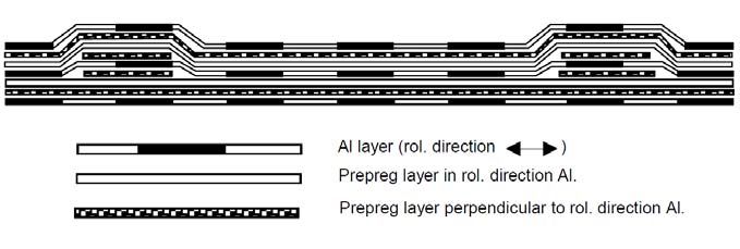
An example in this case may be interlaminar doublers, see Figure 7. When for reasons of
mechanical joining (minimum required bearing strength) a higher MVF is required in a specific
area of the structure, this could be achieved not by increasing the FML or aluminum layer
thickness in the FML, but by applying additional metal layers in the area where needed. As a
consequence, the FML locally may consist of a different laminate configuration with its own
strength characteristics, while the base FML remains unaffected.
Fibre layer
Interlaminar
Metal layer doubler Adhesive
Figure 7. Illustration of the interlaminar doubler
A similar example has been presented in [23]. In order to reach the minimum required residual
strength of the FML Glare in the forward fuselage of the A380, the FML configuration has not
been changed in the entire panel, but additional glass fiber straps have been applied interlaminar
locally underneath the frames, see Figure 8. This solution is often denoted as ‘Glare improved’.
The application of this design freedom implies that the structure and the related design
constraints and requirements have to be identified first, before the appropriate FML can be
determined. This is opposite to the design approach applied nowadays, where the FML is
designed first, before the actual structure has been determined [7].
Figure 8. Illustration of the interlaminar crack stopping fiber straps [23]5. CONCLUSIONS
This paper presented an overview of the development aspects of FMLs relevant for the fatigue
and damage tolerance assessment. Based on the discussion some conclusions can be put forward:
The FML concept is a structural concept that requires a different F&DT approach than currently
applied to metallic structures
In the F&DT assessment a distinction must be made between the individual constituents and
their contribution to the fracture mechanisms.
To describe the fatigue and fracture behavior of FMLs, the methods for monolithic metallic
structures can not be applied directly. However, if the all failure mechanisms are described
together, the principle of similitude can be used to describe the initiation and crack growth in the
metallic constituents of the FML.
To fully benefit from the F&DT characteristics of FMLs, the FMLs should be designed from a
structural perspective, i.e. the structure and related requirements should define the FML, rather
than that an FML is ‘designed’ which then has to be tailored to the structure.
6. REFERENCES
1. Vlot, Ad. Glare – history of the development of a new aircraft material. Kluwer Academic
Publishers, Dordrecht, 2001.
2. Vogelesang, L.B., “Fibre Metal Laminates – The Development of a New Family of Hybrid
Materials.” ICAF 2003 fatigue of Aeronautical Structures as an Engineering Challenge. Ed.
M. Guillaume. Emas Publishing, Sheffield UK, 2004.
3. Marissen, Roel, Fatigue Crack Growth in ARALL, A hybrid Aluminium-Aramid Composite
Material, crack growth mechanisms and quantitative predictions of the crack growth rate,
PhD Thesis, University of Technology Delft, 1988.
4. Roebroeks, Geert, Towards GLARE - The Development of a fatigue insensitive and damage
tolerant aircraft material, PhD Thesis, Delft University of Technology, 1991.
5. Schijve, J., Fatigue of Structures and Materials, Springer Science+Business Media B.V,
2009.
6. Roebroeks, G.H.J.J., Fibre-metal laminates, Recent developments and applications, Fatigue
16 (1), 33-42, 1994.
7. Roebroeks, G.H.J.J., Hooijmeijer, P.A., Kroon, E.J., Heinimann, M.B., The development of
CentrAl, First International Conference on Damage Tolerance of Aircraft Structures, R.
Benedictus, J. Schijve, R.C. Alderliesten, J.J. Homan (Eds.), © TU Delft, The Netherlands
8. Schmidt, H.J., In: Structural Integrity of Advanced Aircraft and Life Extension for Current
Fleets – Lessons Learned in 50 Years after the Comet Accidents, Proceedings of the 23rd
ICAF Symposium, vol. I, pp. 1–41, Dalle Donne, C. (Ed.), DGLR, Germany, 2005.9. Alderliesten, R.C., Fatigue & Damage Tolerance of Hybrid Materials & Structures – some
myths, facts & fairytales, ICAF proceedings, 2009.
10. Kawai, M., Hachinohe, A., Takumida, K., Kawase, Y., Off-axis fatigue behaviour and its
damage mechanics modelling for unidirectional fibre–metal hybrid composite: GLARE 2,
Composites: Part A 32, 13–23, 2001.
11. Kawai, M., Hachinohe, A., Two-stress level fatigue of unidirectional fiber–metal hybrid
composite: GLARE 2, International Journal of Fatigue, 24 (5), 567-580, 2002.
12. Kawai, M., Kato, K., Effects of R-ratio on the off-axis fatigue behavior of unidirectional
hybrid GFRP/Al laminates at room temperature, International Journal of Fatigue, 28 (10),
1226-1238, 2006.
13. Takamatsu, T., Shimokawa, T., Matsumura, T., Miyoshi, Y., Tanabe, Y., Evaluation of
fatigue crack growth behavior of GLARE3 fiber/metal laminates using a compliance method,
Engineering Fracture Mechanics 70, 2603–2616, 2003.
14. Harris, Bryan, Preface, Ed. Bryan Harris, Fatigue in composites, Woodhead Publishing Ltd,
Cambridge England, 2003.
15. Wilson, G.S., Alderliesten, R.C., Benedictus, R., Steady-state crack growth in hybrid fiber
metal laminates as a tool for design, SAMPE conference, Seattle, 2010.
16. Rans, C.D., The role of rivet installation on the fatigue performance of riveted lap joints, PhD
thesis, Carleton University, Canada, 2007.
17. Alderliesten, R.C., Damage tolerance of bonded aircraft structures, First International
Conference on Damage Tolerance of Aircraft Structures, R. Benedictus, J. Schijve, R.C.
Alderliesten, J.J. Homan (Eds.), © TU Delft, The Netherlands
18. Alderliesten, R.C., Hagenbeek, M., Homan, J.J., Hooijmeijer, P.A., De Vries, T.J.,
Vermeeren, C.A.J.R., Fatigue and Damage Tolerance of Glare, Applied Composite
Materials 10, 223–242, 2003.
19. Randell, C.E., Subsurface fatigue Crack Growth in Glare Fibre Metal Laminates, PhD thesis,
Delft University of technology, 2005.
20. Wilson, G. Alderliesten, R., Rodi, R., Lemmen, H.J.K., Practical applications of
improvements in FML crack bridging theory, ICAF proceedings, 2009.
21. Jensen, B. J., Cano, R.J., Hales, S.J., Alexa, J.A., Weiser, E.S., Loos, A.C., Johnson, W.S.,
Fiber metal laminates made by the VARTM process, ICCM-17 17th International Conference
on Composite Materials, 27-31 Jul. 2009, Edinburgh, United Kingdom.
22. Mangkoesoebroto, R.H., The Effect of Fibre Volume Fraction on the Mechanical Properties
and the Fatigue Behaviour of ARALL Laminates, MSc. Thesis, Delft University of
Technology, 1987.
23. Vlot, A., Gunnink, J.W. (Eds)., Fibre Metal Laminates an introduction, Kluwer Academic
Publishers, Dordrecht, The Netherlands, 2001.You can also read