Experimental research on effect of opening configuration and reinforcement method on buckling and strength analyses of spar web made of composite ...
←
→
Page content transcription
If your browser does not render page correctly, please read the page content below

Science and Engineering of Composite Materials 2021; 28: 190–203
Research Article
Lin Sen*, Li Chenxi, Hu Ying, and Cong Hao
Experimental research on effect of opening configuration and
reinforcement method on buckling and strength analyses of
spar web made of composite material
https://doi.org/10.1515/secm-2021-0018 material used in aircrafts has become one of the important
received December 30, 2020; accepted April 21, 2021 indexes to measure the advantage of aircraft structures [1].
Abstract: This study experimentally investigates the effect With the increased usage of the composite material in
of the opening configuration on the buckling stability and an aircraft, it is crucial for engineers in the aviation
bearing performance of a structural beam web used in a industry to investigate the mechanisms of the composite
commercial aircraft made of composite materials. The materials. Due to the anisotropy of the single-layer mate-
buckling and strength analyses on three opening config- rial, the mechanical properties and other properties of
urations (circular, oblong, and rhombic) were carried out composite laminates are very complex. These composite
using test samples with identical web surface size. It is laminates show different mechanical properties in dif-
found that the rhombic opening has the minimum effect ferent directions.
on the buckling stability and strength of the structure. To Composite-laminated plate structures are utilized as
compensate for the effect of the opening, two reinforce- the shell or plate structure in a commercial aircraft for its
ment methods, using reinforcement rib and thickening the advanced properties. In the service process, it bears in-
sample, were also investigated in this study. It is con- plane load. With the application of in-plane compression
cluded that thickening the sample can more effectively or shear load, the plate or shell structure buckles. The
improve the buckling stability and strength performance buckling of structure and the damage lead to the decrease
of beam web structure and hence has relatively higher in structural reliability and could result in the loss of
structural reinforcement efficiency. function. In order to meet the functional requirements
of composite structure in service, the need for an opening
Keywords: composite structure, buckling, FEM in a subcomponent is commonly required in practice.
Openings are provided in structural subcomponents for
ventilation and to lighten the weight of the structure.
In aircraft subcomponents (such as wing spar and
1 Introduction ribs), openings are necessary for access, inspection, and
the installation of the electric lines and fuel lines. The
Composite materials are commonly used in aircraft struc- stress/strain distribution of the structure with openings
tures in the last few decades. The percentage of the com- under external load is very complex. The stress concen-
posite materials in the aircraft structure of B787 is higher tration at the hole is often obvious, and the decrease in
than 50% of its total weight. The amount of composite the effective area of the structure and its mechanical
properties (such as the stability of the structure) signifi-
cantly changes during the bearing process. The presence
of the openings will inevitably lead to the complexity of
* Corresponding author: Lin Sen, Shanghai Aircraft Design and the stress and strain distribution in the laminate struc-
Research Institute, Commercial Aircraft Corporation of China Ltd
ture. The buckling behavior of composite laminates with
(COMAC), Shanghai 201210, China, e-mail: linsen@comac.cc
Li Chenxi: Shanghai Aircraft Design and Research Institute, openings needs further research and exploration.
Commercial Aircraft Corporation of China Ltd (COMAC), Shanghai In the field of aviation structure design, the opening
201210, China, e-mail: lichenxi@comac.cc is a weak structure in the composite structure bearing.
Hu Ying: Shanghai Aircraft Design and Research Institute, Consequently, it is necessary to strengthen the structure
Commercial Aircraft Corporation of China Ltd (COMAC), Shanghai
around the opening area. Researchers aimed to study the
201210, China, e-mail: huying2@comac.cc
Cong Hao: Shanghai Aircraft Design and Research Institute,
bearing properties of composite laminated plates with
Commercial Aircraft Corporation of China Ltd (COMAC), Shanghai openings in order to provide methods for the design
201210, China, e-mail: conghao@comac.cc opening structure and reinforcement.
Open Access. © 2021 Lin Sen et al., published by De Gruyter. This work is licensed under the Creative Commons Attribution 4.0 International
License.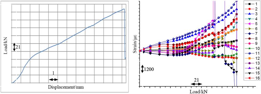
Opening configuration and reinforcement of composite spar web 191
The experimental study on the buckling behavior of out the buckling analysis of composite shell structure
composite laminates with circular openings was conducted with opening under compression load by FEM. The effects
by Srinivasa et al. [2]. It is found in their study that the of panel, opening size, and the ratio of opening radius
existence of openings weaken the buckling capacity of com- to plate thickness on buckling load are studied in
posite’s thin-walled structures. To analyze the stress/strain their work. Ubaid et al. [14] explored the mechanical
aspect, Wang et al. [3] and Toubal et al. [4] studied the stress properties of composite laminates with multiple openings
concentration phenomenon at the edges of circular holes on through experiments and simulations. Riccio et al. [15]
composite laminates under tensile load by experiments. studied the compressive behavior of an omega-stiffened
Zitoune et al. [5] carried out tests on the tensile properties panel with large notch damage and found that the panel
of quasi isotropic laminates with drilled and molded holes. with large notch damage started at the notch edges and
The test results show that the damage mechanisms of lami- propagated toward the panel edges in the direction per-
nates with drilled holes and molded holes are different, and pendicular to the loading direction, which leads to a net
the strength of laminates with molded holes is 20% higher tension failure mode. Sellitto et al. [16] studied the com-
than that of laminates with drilled holes of the same size, pressive behavior of a notched omega-stiffened compo-
indicating that drilling on laminates and cutting fibers have site panel by comparing the experimental and numerical
negative influence on the strength of laminates. Caminero results and found that the ultimate load, buckling beha-
et al. [6] used digital image correlation to analyze the vior, strain distribution, and failure have good agree-
damage process of composite laminates with holes under ment; and the buckling of the structure can overcome
uniaxial tensile load. the initial influence of the large notch damage. Muc
Jalaei and Civalek [7] studied the dynamic instability et al. [17] studied the buckling and postbuckling beha-
of embedded porous functionally graded (FG) nanobeam viors of laminated plated and shell structures. Their
with viscoelastic property undergoing a periodic compres- numerical analysis showed that the postbuckling beha-
sive load and found the influences of various significant vior was associated with the increase in deformations,
factors, such as static load factor, foundation type, length and the fracture of the plate may occur if the deformation
to thickness ratio, power-law index, magnetic field, non- continues to increase. Baltacci et al. [18] studied the
local parameter (NP), and porosity volume index, can buckling analysis of laminated composite circular plates
affect the dynamic instability of porous FG nanobeam. with circular holes and subjected to uniform radial load
Akgöz et al. [8,9] provided a new nonclassical sinusoidal by using FEM. The effects of the factors, hole sizes, loca-
plate model that was developed on the basis of modified tion of the holes, thickness, and boundary conditions on
strain gradient theory. It is found that the size dependency the critical buckling load were investigated. It is found
of the microplate was more prominent when the thickness that the critical buckling load decreases as the hole size
of the microplate was close to the material length scale and thickness variation in the composite circular plate
parameter, and the effect of the shear deformation became increase, and increases as the distance between the loca-
important for thick microplates with low length-to-thickness tion of the hole and the center of the composite circular
ratio. Dastjerdi et al. [10] studied the mechanical response plate increases. Zhang et al. [19] used the 3D progressive
of spherical viscoelastic functionally graded material (FGM) damage analysis model to study the damage mechanism
nanostructures with a change in the structure thickness. of open-hole composite laminates under longitudinal
Moore et al. [11] studied a scaled composite test section, loads and found that the fiber damage of 0° plies propa-
used ply-based modeling to validate the composite of wing gates mostly in line, and as long as any damage in 0° ply
attachment hardware, and obtained a good method to evaluate spreads to the outer edge of the specimen and the spe-
the full-size wing spar bearing. Fraternali et al. [12] studied cimen loses its loading capacity. The conclusion of their
in-plane and out-of-plane buckling of laminated composite work is that the damage of 0° ply is recommended to
arches on curved case and found that the bimodularity ratio represent the damage extent of composite structures.
of the material strongly affects the postbuckling behavior of the To compensate for the negative effect of the opening,
beam, leading to stable response when the material is stiffer in many efforts have been made to understand the reinforce-
tension than in compression and that warping effects play a ment methods. Shi et al. [20] proved that properly designed
significant role in the buckling loads of composite beams. ribs can effectively improve the structural buckling and post-
Besides the experimental methods, finite element buckling-bearing capacity of stiffened composite cylindrical
method (FEM) has been used to investigate the opening shells with openings under axial compression load. Other
configurations and the bearing capacity and buckling scholars have also studied the stability reinforcement ana-
stability of composite structure. Arbelo et al. [13] carried lysis of composite cylindrical shells with openings [21,22].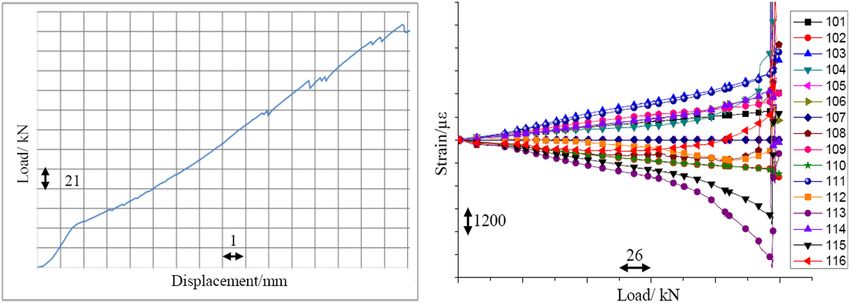
192 Lin Sen et al.
It is noted that most of the studies mentioned above load to the samples, as shown in Figure 1. Figure 1(I)
focus on the composite structure with single-opening con- illustrates the test loading mode and it is seen that the
figuration and their features. The investigation on the boundary condition for the sample is simply supported at
bearing properties arising from different configuration of the edges of the sample, and it carries a quasi-static shear
the openings as well as the reinforcement method is limit- load in plane by the tensile load applied in the diagonal
ed. In order to reduce the influence of openings and rein- direction. The arrows in Figure 1(I) denote the directions
force structures, it is necessary to study different openings where the shear load is applied. The cross section of the
and the reinforcement methods of composite structure. sample is shown in Figure 1(II), the strain measurement
According to the bearing mode of the beam, it is positions are shown in Figure 1(Ш).
known that the beam web mainly bears shear load under Strain rosettes were placed in the diagonal direction.
the bending moment. The common failure mode of the Strain gauges were placed at the upper, lower, left, and
beam web under shear load is buckling instability and right positions of the samples; and they were close to the
consequently failure. In this study, experimental research edges of the opening.
and numerical simulation are conducted to study the
influence of different opening configurations and dif-
ferent structural reinforcement methods of composite
materials on the buckling bearing capacity and strength 2.2 Samples
performance of beam web under shear load. By com-
paring the different opening configurations and reinfor- In this study, the samples for the experiments are based
cement methods, the design of the opening configuration on the “I-shaped” beams. The cross sections of nine test
in beam web structure is experimentally and numerically samples are shown in Figure 2. The opening is placed in
optimized. Due to the common usage of the openings in the middle of each web sample, and the diameter or the
the composite laminates, this work provides a guideline equivalent diameter of each opening is at least 100 mm.
for the structural design in the civil aviation industry and The size of the composite sample is 400 mm × 280 mm.
is worthy of further research. The shapes of the openings in the samples are circular,
oblong, and rhombic. All samples are of line symmetric.
The two symmetric lines are perpendicular to each other
and one of them lays horizontally across the center of the
2 Scheme of measurements opening, as shown in Figure 2.
Figure 2 illustrates the configuration of the test sam-
2.1 Measurement setup ples. Samples a1, b1, and c1 were utilized to investigate
the effect of the three opening shapes on the buckling
This section describes the scheme of the measurements. stability and bearing performance. Note that the opening
To investigate the effect of the opening configuration on area of the sample with the oblong opening (b1) is sig-
the buckling stability and bearing performance of a com- nificantly larger than those of the samples with the cir-
ponent of a beam web made of composite materials, a cular and rhombic openings (a1 and c1). Samples a2 and a3
sample holding section was designed to apply the shear are the reinforced samples with circular openings using
Figure 1: Schematic diagram of the sample-holding section. (I) Test loading mode. (II) Sample section. (III) Strain measurement position.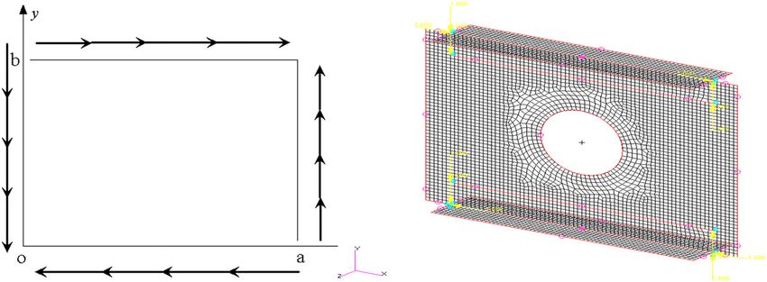
Opening configuration and reinforcement of composite spar web 193
Figure 2: Samples for the experiments. a1, b1, and c1: samples with circular, oblong, and rhombic openings; a2, b2, and c2: those reinforced
by ribs; a3, b3, and c3: those reinforced by thickening the web. In sub-figures a2, b2, and c2 of Figure 2, the dimensions and the positions of
the ribs used for reinforcement are shown in detail.
rib reinforcement and thickening reinforcement, respec- 3 Analysis of test results
tively. Samples b2 and b3 are the reinforced structures
with oblong openings, and c2 and c3 are those with
3.1 Data acquisition
rhombic openings. The sizes of the openings in a2 and
a3 are identical to that in a1 and it is the same with these The test results of a1/a2/a3/b1/b2/b3/c1/c2/c3 are shown
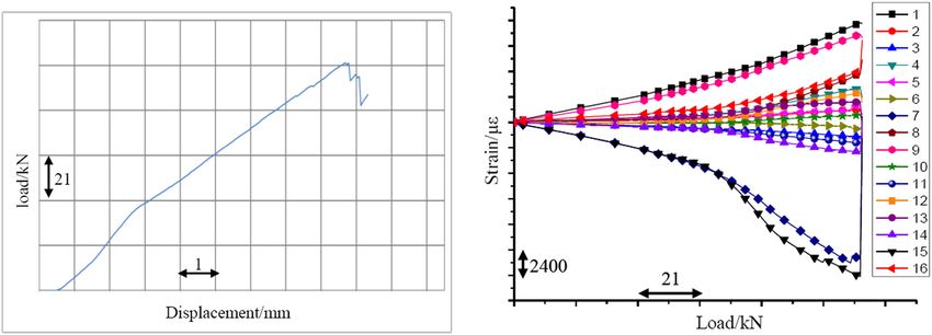
in b and c groups. Other properties of the composite in Figures 3–11. Each figure has two subfigures. The left-
materials used for these samples are summarized in hand side subfigure in each figure is the load–displace-
Tables 1 and 2. All the openings are in the center of the ment curve which records the change in the displacement
sample, and all the stiffeners are the same. with the increase in the shear load. The right-hand side
Table 1: The composite skins with different configuration
Structure Plies
Web [45/−45/0/45/−45/0/−45/90/45]s
Flange [45/−45/0/0/45/90/−45/0/0/−45/45/45/−45/0/0/0/−45/0/0/0/45/90/45/0/0/0/−45/0/0/0/−45/45]
Web flange [45/−45/0/0/45/90/−45/0/0/−45/90/45]s
Thickening reinforcement [45/−45/0/0/45/90/−45/0/0/−45/90/45]s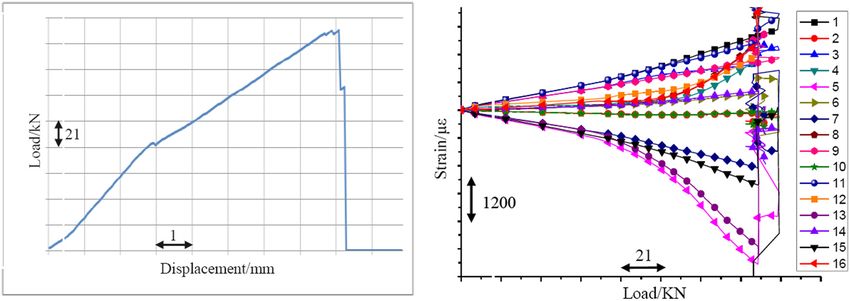
194 Lin Sen et al.
Table 2: The mechanical properties of the ply surface layer failure. According to the measured load–
displacement curves, composite material webs were linear
Parameter Ply elastic in the whole process of destruction. Moreover, the
E11 152,000 MPa measured strain steadily increased at the bulking process
E22 7,600 MPa until broken, which implies that the test samples were in
v12 0.35 elastic region during the buckling tests and the plastic
G12 3,900 MPa behaviors did not appear.
Thickness 0.18 mm
By comparing curves and test video, each sample’s
bulking and initial failure capacity are obtained. The
sample test results are summarized in Table 3.
subfigure of each figure possesses 16 curves which repre-
sent the measured strain in 16 different positions on the
measured sample.
In the test process, the holes of test appear buckling 3.2 Data analysis
first, and load displacement has some undulations, and
then the buckling has larger deformation with the tensile According to Table 3, the buckling carrying capacity of a1
load increasing. When having some damage sounds, at as a reference is 100%; Table 4 shows the calculation of
last the samples have inner or surface damage and some the relative proportions of other sample’s carrying capa-
load–strain curves have sudden shifts. The failure mode cities. By the same way, considering the initial failure
involves the diagonal hole edge failure and then the carrying capacity of Sample a1 as a reference, the relative
Figure 3: a1-type test curve.
Figure 4: a2-type test curve.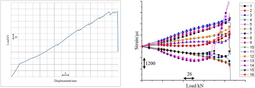
Opening configuration and reinforcement of composite spar web 195
Figure 5: a3-type test curve.
Figure 6: b1-type test curve.
Figure 7: b2-type test curve.
proportions of other sample’s initial failure strength are This implies that the rhombic opening is able to carry the
calculated as shown in Table 5. highest shear load without reinforcement. Hence, the
In the second column of Table 3, the comparison of rhombic opening is supposed to be the optimized config-
a1, b1, and c1 demonstrates that Sample c1 has the uration of the three opening configurations. To investi-
highest bending carrying load among the three samples. gate the effect of the reinforcement method on the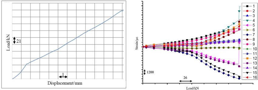
196 Lin Sen et al. Figure 8: b3-type test curve. Figure 9: c1-type test curve. Figure 10: c2-type test curve. bending carrying load, the results of the samples labeled observed with groups b and c, which implies that using 1, 2, and 3 are compared in each group of samples with the thickening reinforcement method can significantly each opening configuration. In group a (samples with improve the bending carrying load. Moreover, Table 4 the circular opening), the bending carrying load peaks shows the relative bending carrying loads of all nine sam- with Sample a3 which is made by using the thickening ples. It is concluded in Table 4 that among all samples, reinforcement method. This phenomenon has also been Sample c3, which is the sample with the rhombic opening
Opening configuration and reinforcement of composite spar web 197
Figure 11: c3-type test curve.
and reinforced by thickening the web, has the highest the reinforcement ribs. However, for thickening reinfor-
bending carrying load. This conclusion is consistent with cement, the bearing capacity of specimens with a, b, and
the data analysis using Table 3. Therefore, the analysis c configuration is increased by 31.7, 46.9, and 23.6%,
of the experimental results illustrates that the rhombic respectively. Note that the reinforcement efficiency is
opening is the best configuration of the three openings even higher when the opening area is larger.
and the relatively better reinforcement method is thick- It is concluded from Tables 3–5 that the thickening
ening the web; and that these two factors could be com- reinforcement provides more advanced buckling carrying
bined to provide the optimized configuration of a composite capacity and higher initial failure load than those of the
laminate with an unavoidable opening in aviation rib reinforcement. This is possibly due to the different-
industry. In the third column of Table 3, the comparison reinforce process. When using the rib reinforcement, it is
of a3, b3, and c3 demonstrates that Sample c3 has the necessary to drill holes on the samples to install the ribs.
highest carrying initial failure load. It indicates that the Drilling holes lead to the break of the composite fibers and
rhombic opening with thickening reinforcement method small cracks near the edges of the drilled holes. Due to the
has the strongest carrying capacity and that the thick-
ening reinforcement can significantly improve the initial
Table 4: Comparison of the relative buckling load
failure carrying capacity. Table 5 compares the relative
initial failure strength of the samples. As for the bearing
a (%) b (%) c (%)
capacity against failure, the reinforcement efficiency of
the rib is very limited, and the bearing capacity is increased Unreinforced structure bulking carrying 100 70.6 122
only by 1–7%. The limited improvement is due to the ratio
Bulking carrying ratio by 110.5 78.3 133.7
buckling resistance at the edge of the opening and the
reinforcement rib
structure damages caused by the hole manufacture for Bulking carrying ratio by thickening 169 147.3 198
reinforcement
Note: a1 is a referent used for comparing with other samples.
Table 3: Test results
Types Test bending carrying Initial failure
Table 5: Comparison of relative initial failure strength
loads (kN) load (kN)
a1 73.6 145.4 a (%) b (%) c (%)
a2 81.4 147.5
a3 124.4 191.6 Unreinforced structure initial failure 100 60 126.3
b1 52 87.4 strength ratio
b2 57.6 92.6 Initial failure strength ratio by 101.3 63.68 135.2
b3 108.4 128.4 reinforcement rib
c1 90 183.6 Initial failure strength ratio by 131.7 88.3 156.1
c2 98.4 196.6 thickening reinforcement
c3 145.75 227
Note: a1 is a referent used for comparing with other samples.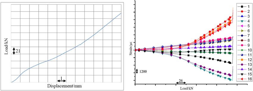
198 Lin Sen et al.
Table 6: Weight comparison of the samples the structure), the bearing capacity of the laminate can be
regarded as a plane stress state. According to the stress–
Sample Weight (kg) Relative weight (%) strain relationship, the generalized constitutive relation
a1 0.987 100 of the laminate (including the membrane bending cou-
a2 1.111 112.5 pling) can be obtained.
a3 1.1 111.4
b1 0.94 95.2 Nx A11 A12 A16 B11 B12 B16 εx 0
Ny
b2 1.064 107 A
12 A A B12 B22 B26 εy0
22 26
b3 1.05 106 Nxy A16 A26 A66 B16 B26 B66 γxy0
M = . (1)
c1 0.996 100.9 D11 D12 D16 κx
x
D26 κy
c2 1.12 113.4
c3 1.12 113.4 My Symmetry D12 D22
M D66 κxy
xy
D16 D26
Note: a1 is a referent used for comparing with other samples.
So stiffener matrix coefficient of laminate can be
expressed as
N
Aij = ∑ (Q˜ ij)k (zk − zk − 1),
k=1
N
1
Bij = ∑ (Q˜ ij)k (zk − zk − 1) ,
2 2
(2)
2 k=1
N
Dij = 1 ∑ (Q˜ ij)k (zk3 − zk3− 1).
3 k=1
Figure 12: The laminates layup of the panel. zk is distance between the central plane of layer k and the
bottom surface, as shown in Figure 12 (Q̃ij)k is the stiffener
of layer k. Aij , Dij , and Bij are the tensile stiffness coeffi-
broken fibers and the cracks, the buckling carrying capa- cient, bending stiffness coefficient, and tensile and bending
city and the initial failure load decrease. By contrast, using coupling stiffness coefficient, respectively.
thickening reinforcement maintains the continuous fibers,
and hence the reinforcement efficiency is higher than that
obtained by adding reinforcement ribs.
4.2 Theoretical analysis
The weights of samples are summarized in Table 6,
and taking the weight of sample a1 as a reference, other
To investigate the mechanism of the beneficiation arisen
sample’s weight relative proportions are calculated as
from the thickening reinforcement, Figure 13 shows the
shown in Table 6. As shown in Table 6, the weights of
distribution of the tensile and bending stiffness parameters
rib reinforcement and thickening reinforcement are almost
of the original beam web and the thickening-reinforced
the same. Since their bearing capacities are significantly
beam web in polar coordinate system. In the original
different, it is concluded that the thickening reinforcement
beam web ply design, the two parameters of tensile stiff-
efficiency is higher than that of the rib reinforcement.
ness cross each other in the 45° direction, which indicates
that the composite mechanical properties in this direc-
tion are the best under the web ply design. After the
design of thickening reinforcement, the tensile stiffness
4 Theoretical analysis of the parameters A11 and A22 have the greatest influence on
improvement of the thickening the beam web in 0° and 90° directions, respectively.
This is because the overall mechanical properties of
reinforcement beam webs are changed after adding 0° and 90° ply to
the beam web. Compared with the original beam web
4.1 Classic laminate theory overlay design, the overall tensile stiffness parameter
increases by about 20%.
For thin-walled composite structures (i.e., the thickness In the original beam web ply design, due to the large
of the laminate is much smaller than other dimensions of proportion of ±45° ply mode, the bending stiffness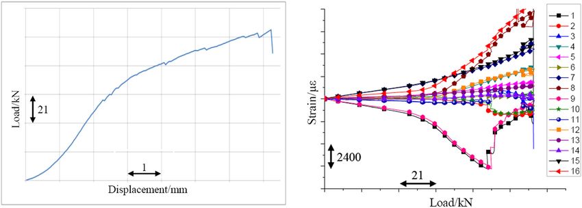
Opening configuration and reinforcement of composite spar web 199
A11 90 300 D11
90
250000000 A12 120 60 D12
120 60 A22 D22
200000000 A16 D16
200
A26 D26
150000000 150 30
A66 D66
150 30
100000000 100
50000000
Dx (N·m)
Ax (N/m)
180 0
180 0
210 330 210 330
240 300 240 300
270 270
Ay (N/m) Dy (N·m)
(I) (II)
A11 D11
90 90 D12
400000000 A12 800
120 60 A22 120 60 D22
A16 D16
300000000 600
D26
A26
D66
A66 150 400 30
150 200000000 30
200
100000000
Dx (N·m)
Ax (N/m)
180 0
180 0
210 330
210 330
240 300
240 300 270
270
Dy (N·m)
Ay (N/m)
(III) (IV)
Figure 13: Tensile stiffness/bending stiffness parameters of web and reinforce web. (I) Web Aij. (II) Web Dij. (III) Reinforce web Aij.
(IV) Reinforce web Dij.
parameters of D11 and D22 are the largest in the direction in the near 50° direction. After the design of thickening
of 45° and 135°, respectively, and form a cross in the reinforcement, the bending stiffness parameters of beam
direction of nearly 50° at the same time, which indicates web are increased by about one time compared with the
that the bending bearing capacity of beam web near 50° original structure. Compared with configuration 1, the
is the strongest. bending stiffness parameters of D11 and D22 are basically
After the thickening reinforcement design, the pro- the same in the direction of 45° compared with config-
portion of 0° and 90° ply increases, and the bending uration 1, but the bending stiffness of D11 and D22 is higher
stiffness parameters have great influence. The bending and more coordinated in the range of 360°.
stiffness parameters of D11 and D22 are the largest in the Through theoretical analysis, it is found that com-
direction of 15° and 105°, respectively, and form a cross in pared with the original structure, the thickness reinforce-
the direction of nearly 50° which indicates that the ment of beam web increases six layers of ply design, but
bending bearing capacity of beam web is the strongest it is very effective to improve the tensile stiffness and200 Lin Sen et al.
bending stiffness parameters and enhances the tensile 5.2 Comparison of FEM and experiment
and bending bearing capacity of the beam web. This
implies that by properly designing the composite layup As shown in Figure 16, the calculation of buckling load by
of the thickening reinforcement, the reinforcement effi- FEA method is compared with those from the experi-
ciency can be improved. ments. The error bars on the curve of the experimental
results denote the acceptable error range of the experi-
ments in practice which is ±15%. This error is usually
arisen from the variation in the samples due to the man-
5 Finite element analysis (FEA) of ufacture process, and the small change in the boundary
condition due to the installation of the samples.
loading buckling of samples For Samples a1, b1, and c1, most of the buckling loads
from the FEM simulations are similar with those from the
5.1 FEM analysis experiments. The differences in the experimental and
simulated buckling loads for Samples a1 and b1 are
In order to further research carrying capacity of the com- within the acceptable error range, which implies that
posite spar web, this section developed an FEA model for the FEM models are valid. For the Sample c1, the differ-
the samples and compares the test results to the simu- ence is slightly higher than the upper limit of the error
lated results by CAE software analysis. The FEA software bar. This might be caused by the manufacture process of
Patran & Nastran is used to establish the FEA model. All the sample and/or the boundary condition of the experi-
the FEM models use the 2D shells and Quad 4 elements to ment. Moreover, the buckling load obtained by the experi-
simulate the mechanical web based on the plane stress ment for Sample c3 agrees with that of the FEM model,
theory. which may imply that the FEM model for the samples in c
The Z direction of the nodes at four edges of the group is still valid and the difference in those of the
sample is constrained. The degree of freedom node Sample c1 is due to the sample itself and the test error
(0,0,0) is constrained by (0, 0, 0). The node (a, b, 0) is due to the experiment process.
constrained with the load tensile direction by local coor- As for the reinforcement method, the FEM results
dinate. The distance is 5 mm between the nearby nodes show trends similar to those of the experiments. It is
at four edges. Unit load is applied to the nodes of four also obvious from the FEM results that the rhombic
edges. opening and the thickening reinforcement method are
The model and loading conditions are shown in beneficial for the buckling capability. The results of FEA
Figure 14 as well as the mesh of the FEA model. The finite are in good agreement with the experimental results of
element buckling analysis results of the test samples are the cases without reinforcement and with the thickening
shown in Figure 15. reinforcement. However, in the analysis of reinforcement
Figure 15 shows the distribution of the bulking factor rib, there is a big difference between FEM calculation
simulated by FEM models. Since the plies of sample web results and test results. The difference implies that the
are symmetrical, both sides of the web demonstrate the damages arisen from drilling holes for the connection
same effect of bulking factor. According to the factor fasteners and processing have great influence on the bearing
and boundary unit loads, the buckling capacity of each capacity of beam web, and these structural damages are
sample is calculated and shown in Table 7. neglected by the FEM model.
Figure 14: FEA model.Opening configuration and reinforcement of composite spar web 201 Figure 15: FEA bending analysis of a/b/c types: (I) FEA bending analysis of Sample a1. (II) FEA bending analysis of Sample a2. (III) FEA bending analysis of Sample a3. (IV) FEA bending analysis of Sample b1. (V) FEA bending analysis of Sample b2. (VI) FEA bending analysis of Sample b3. (VII) FEA bending analysis of Sample c1. (VIII) FEA bending analysis of Sample c2. (IX) FEA bending analysis of Sample c3.
202 Lin Sen et al.
Table 7: FEA bending results aviation industry. By selecting the appropriate opening
form and the reinforcement design method, the loss of
Type Factor Buckling capacity (kN) bearing capacity due to the opening can be effectively
a1 799.51 66.95 improved, and the structure design efficiency can be signi-
a2 1,204.9 100.90 ficantly improved, which has economic benefits.
a3 1,550.7 129.86
b1 637.9 53.41 Conflict of interest: Authors state no conflict of interest.
b2 1,044 87.42
b3 1,455.2 121.8
c1 926.57 77.59
c2 1,359.8 113.87
c3 1,824.8 152.81 References
[1] Tang JM. Current status and trends of advanced composites in
aerospace. Spacecr Environ Eng. 2013;30:352–9.
[2] Srinivasa CV, Prema Kumar WP, Prathap Kumar MT, Bangar AR,
Kumar P, Rudresh MS. Experimental and numerical studies on
buckling of laminated composite skew plates with circular
holes under uniaxial compression. Mech Adv Mater Struct.
2017;24:304–17.
[3] Wang Z, Li H, Tong J, Shen M, Aymerich F, Priolo P. Dual
magnification digital image correlation based strain mea-
surement in CFRP Laminates with open hole. Compos Sci
Technol. 2008;68:1975–80.
[4] Toubal L, Karama M, Lorrain B. Stress concentration in a circular
hole in composite plate. Compos Struct. 2005;68:31–6.
[5] Zitoune R, Crouzeix L, Collombet F, Tamine T, Grunevald YH.
Behaviour of composite plates with drilled and moulded hole
Figure 16: FEA simulation and test on buckling capacity. under tensile load. Compos Struct. 2011;93:2384–91.
[6] Caminero MA, Lopez-Pedrosa M, Pinna C, Pinna C, Soutis C.
Damage monitoring and analysis of composite laminates
with an open hole and adhesively bonded repairs using
6 Conclusion digital image correlation. Compos Part B: Eng. 2013;53:76–91.
[7] Jalaei M, Civalek Ö. On dynamic instability of magnetically
embedded viscoelastic porous FG nanobeam. Int J Eng Sci.
This study used experiments to investigate the effect of
2019;143:14–32.
the opening configuration on the buckling stability and [8] Akgöz B, Civalek Ö. A microstructure-dependent sinusoidal
bearing performance of a structural beam web used in a plate model based on the strain gradient elasticity theory. Acta
commercial aircraft made of composite materials. The Mech. 2015;226:2277–94.
buckling and strength analyses on three opening config- [9] Civalek Ö, Dastjerdi S, Akbas SD, Akgöz B. Vibration analysis
urations (circular, oblong, and rhombic) were conducted of carbon nanotube-reinforced composite microbeams. Math
Methods Appl Sci. 2021;121:800. doi: 10.1002/mma.7069.
using test samples with identical web surface size.
[10] Dastjerdi S, Akgöz B, Civalek Ö. On the effect of viscoelasticity
It is concluded from the experimental results that the on behavior of gyroscopes. Int J Eng Sci. 2020;149:103236.
rhombic opening has the minimum effect on the buckling [11] Moore JB, Cutright SE. Structural analysis and performance-
stability and strength of the structure. To compensate the based validation of a composite wing spar. AIAA Scitech 2019
effect of the opening, it is concluded that thickening of Forum. doi: 10.2514/6.2019-0548.
[12] Fraternali F, Spadea S, Ascione L. Buckling behavior of curved
the sample can more effectively improve the buckling
composite beams with different elastic response in tension
stability and strength performance of beam web structure and compression. Compos Struct. 2013;100:280–9.
and hence has relatively higher structural reinforcement [13] Arbelo MA, Herrmann A, Castro SGP, Khakimova R,
efficiency. By using the analytical analysis and the FEA Zimmermann R, Degenhardt R. Investigation of buckling
model, it is found that the advantage of the thickening behavior of composite shell structures with cutouts. Appl
reinforcement is due to the continuous fibers and the Compos Mater. 2015;22:623–36.
[14] Ubaid J, Kashfuddoja M, Ramji M. Strength prediction and
well-designed fiber layup.
progressive failure analysis of carbon fiber reinforced polymer
The research results are of great significance for laminate with multiple interacting holes involving three
the design of the opening form and the analysis of the dimensional finite element analysis and digital image corre-
bearing capacity of composite beam web structures in lation. Int J Damage Mech. 2014;23:609–35.Opening configuration and reinforcement of composite spar web 203
[15] Riccio A, Sellitto A, Saputo S, Russo A, Zarrelli M, Lopresto V. [19] Zhang D, Zheng X, Wu T. Damage characteristics of open-hole
Modelling the damage evolution in notched omega stiffened laminated composites subjected to longitudinal loads.
composite panels under compression. Compos Part B: Eng. Compos Struct. 2019;230:111474–220.
2017;126:60–71. [20] Shi S, Sun Z, Ren M, Chen H, Hu X. Buckling response of
[16] Sellitto A, Riccio A, Russo A, Zarrelli M, Toscano C, Lopresto V. advanced grid stiffened carbon fiber composite cylindrical
Compressive behaviour of a damaged omega stiffened panel: shells with reinforced cutouts. Compos Part B: Eng.
damage detection and numerical analysis. Compos Struct. 2013;44:26–33.
2019;209:300–16. [21] Jingxuan H, Mingfa R, Qizhong H, Shanshan S, Haoran C.
[17] Muc A, Chwal M, Barski M. Remarks on experimental and Buckling behavior of compression-loaded advanced grid stif-
theoretical investigations of buckling loads for laminated fened composite cylindrical shells with reinforced cutouts.
plated and shell structures. Compos Struct. 2018;203:861–74. Polym Polym Compos. 2011;19:357–62.
[18] Baltacci A, Sarikanat M, Yildiz H. Buckling analysis of lami- [22] Hilburger MW, Starnes JH Jr. Buckling behavior of compres-
nated composite circular plates with holes. J Reinfor Plast sion-loaded composite cylindrical shells with reinforced cut-
Compos. 2006;25:733–44. outs. Int J Non-linear Mech. 2005;40:1005–21.You can also read