Failure and Technology Analysis - Multi Layer Ceramic Capacitors (MLCC) one of the most mechanical sensitive component
←
→
Page content transcription
If your browser does not render page correctly, please read the page content below

Failure and Technology Analysis

                                  Multi Layer Ceramic
                                   Capacitors (MLCC)
                                    one of the most
                                  mechanical sensitive
                                      component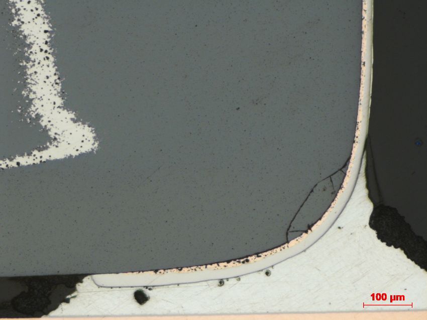
„It's Not the Fall That Kills You, It's The Sudden Stop At The End”
                                                    Douglas Adams

„It's Not the Crack That Kills Your Capacitor, It's The Electrical Short After Some Time“
                                                     RoodMicrotec

 Services Failure & Technology Analysis                                                        2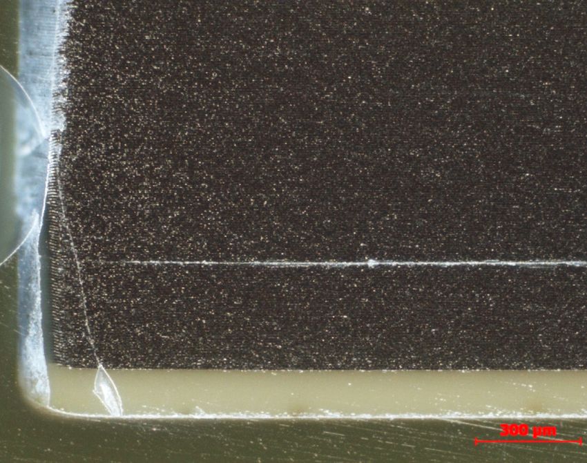
What is a Multi Layer Ceramic Capacitor (MLCC)?
Structure Ceramic
Termination
• Ceramic block dielectric
• Embedded metal layers
• Termination on both sides
Advantages
• Material admixtures enabling modifications
in electrical behavior
Internal electrode
• Stable over temperature and frequency layers
• Small package size
• Good HF behavior
Disadvantages
• Susceptible against over voltage and
voltage spikes
• High mechanical sensitivity
3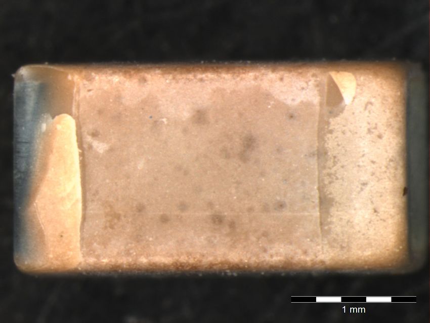
Migration and dendrite growth
Cracked capacitors are
hardly detectable within
outgoing inspection
Silver migration or dendrite
formation through the crack
resulting in an electrical Cross section showing short circuit
short circuit
Approximately after 6 to 24
months in the field the
assemblies fail with burned
capacitors due to electrical
shorts between capacitor
plates
Silver migration MLCC after “rapid unscheduled disassembly”
4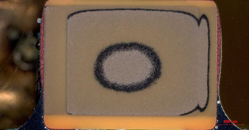
Typical Failures of MLCC
~ 90 % of MLCC field failures are caused by mechanical
overstress, resulting in so called „Flex Cracks“
• Critical processes are component assembly, assembly of press-
Typical
fit components, Failures
singulation ofpanels
of multi MLCC and assembly in the
system
• High mechanical stresses occur at the edge of the printed circuit
board (recommended distance greater than 5 mm), close to
press-fit connectors, near large components and close to
(screw) mounting points. These places are to be avoided.
• Electrical board tests detects roughly 1% of the
cracked devices
• Not visible by optical inspection
Electrical Damage
Manufacturing defects
5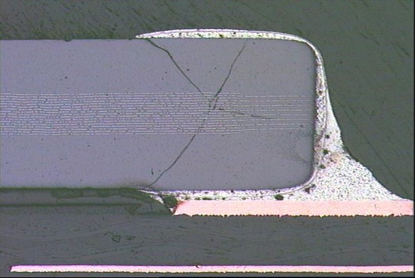
Analysis methods
Metallographic cross sectioning
• Inhomogeneity's within component visible
• Electrical monitoring possible
• Costly
• Destructive
• Only one plane at a time inspectable
• Mechanical stress due to sample preparation (sawing Metallographic cross section of broken capacitor
out)
Optical inspection after chemical removal of the
terminal metallization
• The preparation of many components can be done
simultaneously
• Non destructive to component body
• Crack position allows conclusions about mechanical
stress
• Thermal and mechanical stress due to sample
preparation (desoldering)
X-ray Analysis
Cracks after removal of metallization
• Non Destructive
• Only large cracks parallel to the beam direction visble
6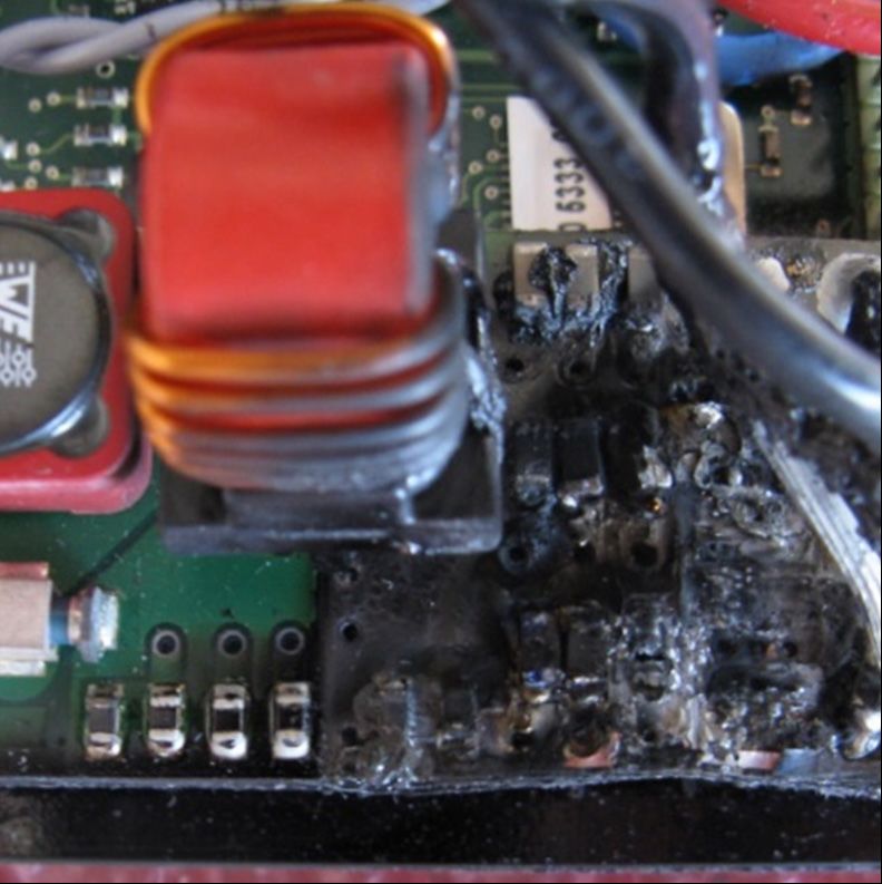
X-Ray Microscopy and why you should not trust it
1 2 3 4
X-Ray microscopy of ceramic capacitors Cross section capacitor 1 Cross section capacitor 2
Capacitors 1 and 2 are more than
obviously broken, but 3 and
especially 4 look relatively
inconspicuous on X-ray electrical
Cross sections revealed massive
damage (electrical as well as
mechanical) of capacitor 3
Capacitor 4 has no visible
damage (in this cross section Cross section capacitor 3 Cross section capacitor 4
plane)
7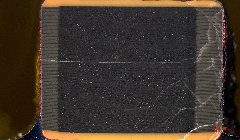
Optical inspection after removal of the terminal metallization
Less time consuming compared to
cross sectioning
Position of crack(s) is visible
• The fracture pattern is depending on
broken edge no cracks chipping in
the course of the bend relative to the corners
orientation of the ceramic capacitor
• Torsion?
• Bending (-direction)?
mechanical
Electrical damage visible
If the capacitor is mounted, thermal
and mechanical stress can occur
due to desoldering
mechanical electrical
8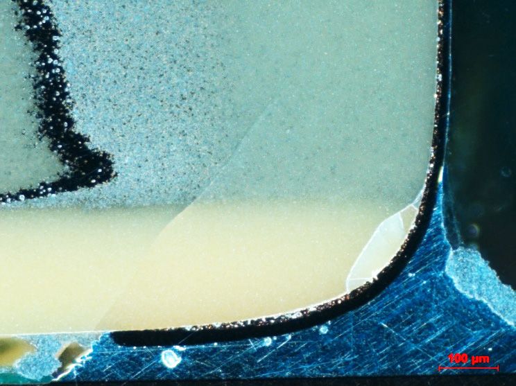
Metallographic Cross Sectioning
Cracks within the capacitor
visible
• Starting at the edge of the solder electrical
joint
• The crack path is always inclined
B A
towards cap mechanical
• The crack always continues
Example of Cross section of MLCC with
towards the terminal Example of Cross section
mechanical and electrical overstress
Electrical monitoring during
grinding possible
Electrical damage clearly visible
(crack along plates)
Cracks are better visible using dark field
Manufacturing defects visible
(e.g. missing plates)
Bright field image at position A Dark field image at position A
9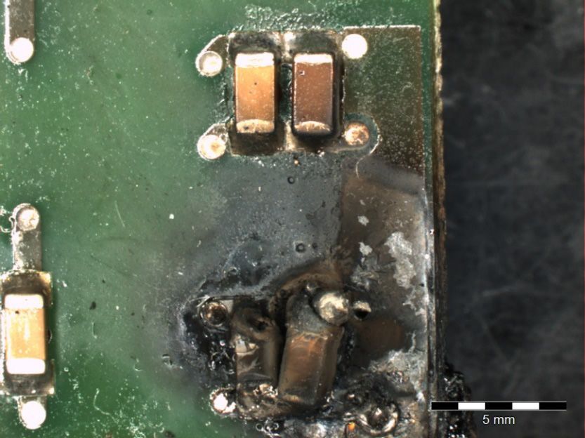
Precaution – Contraceptives
Flex cap – avoid the crack PCBA design
unfavorable
• Silver-filled polymer mass between
silver terminal and nickel-tin layer bad bad
compensates for mechanical forces
Centre of
optimal
optimal
the bend
bad bad
unfavorabl
Capacitor near press fit connection
e
Ceramic
Silver Polymer mass
with silver
Nickel
Tin Capacitor near mounting point
10If it happened – Emergency Contraception
Fail safe capacitors
• Fail open type - no overlap of the
electrodes in the terminal area
• Floating center plates - no short circuit
between the two component
connections possible
Serial connection of two capacitors
• No hard short circuit if one capacitor
fails
11Committed to Quality
Accredited and certified lab
according to
General
The test laboratories are accredited according to DIN EN ISO/IEC 17025:2018 by the accreditation body DAkkS. The accreditation is valid only for the scope listed in the annex of the accreditation certificates
D-PL-12120-01-02.
12Get in Touch With Us
Contact us
Your info@roodmicrotec.com
Reliable
General Tel: +49 9081 804-0
Partner
Visit us
in Business!
www.roodmicrotec.com
Follow us
13You can also read