Polyethylene Nanocomposites for Power Cable Insulations - MDPI
←
→
Page content transcription
If your browser does not render page correctly, please read the page content below
Review

Polyethylene Nanocomposites for Power Cable
Insulations
Ilona Pleşa1,*, Petru V. Noţingher 2, Cristina Stancu 2, Frank Wiesbrock 1 and Sandra Schlögl 1
 1 Polymer Competence Center Leoben GmbH (PCCL), Roseggerstrasse 12, 8700 Leoben, Austria;
   ilona.plesa@pccl.at, frank.wiesbrock@pccl.at (F.W.); sandra.schloegl@pccl.at (S.S.)
 2 Faculty of Electrical Engineering, Electrotechnical Material Laboratory, University Politehnica of Bucharest,

   Splaiul Independentei 313, 060042 Bucharest, Romania; petrunot@elmat.pub.ro (P.V.N.),
   cstancu@elmat.pub.ro (C.C.)
 * Correspondence: ilona.plesa@pccl.at; Tel.: +43-3842-42962-53

 Received: 17 October 2018; Accepted: 18 December 2018; Published: 24 December 2018

 Abstract: This review represents a comprehensive study of nanocomposites for power cables
 insulations based on thermoplastic polymers such as polyethylene congeners like LDPE, HDPE and
 XLPE, which is complemented by original results. Particular focus lies on the structure-property
 relationships of nanocomposites and the materials’ design with the corresponding electrical
 properties. The critical factors, which contribute to the degradation or improvement of the electrical
 performance of such cable insulations, are discussed in detail; in particular, properties such as
 electrical conductivity, relative permittivity, dielectric losses, partial discharges, space charge,
 electrical and water tree resistance behavior and electric breakdown of such nanocomposites based
 on thermoplastic polymers are described and referred to the composites’ structures. This review is
 motivated by the fact that the development of polymer nanocomposites for power cables insulation
 is based on understanding more closely the aging mechanisms and the behavior of nanocomposites
 under operating stresses.

 Keywords: thermoplastic nanocomposite; polyethylene; power cable insulation; electrical property;
 structure-property relationship

1. Introduction
     High-voltage industry undergoes continuous development and modernization of power grid
systems in order to yield reliable, cost-effective and environmentally harmless power solutions [1].
Energy power transportation across the seas and inland is targeted to be performed in particular by
extruded polymer-based cables. Underground and submarine cables are used since the early stages of
electricity transmission and distribution [2]. However, in regions where it is difficult or impossible to
implement the overhead transmission network (i.e. densely populated zones or underwater and
underground tunnels connections), high-voltage alternate current (HVAC) and high-voltage direct
current (HVDC) cable networks are developed to meet the increasing capacity (Figure 1) [1]. In order
to increase their levels of operating voltage and to enhance their electrical performance, it is necessary
to introduce the next generation of cable insulation materials [3].
     Fifty years ago, paper-insulated and oil-impregnated low-voltage (LV), medium-voltage (MV)
and high voltage (HV) underground cables were used [4]. An important development took place in
the 1960s, when mineral impregnation oil was mixed with small quantities of natural resin or
microcrystalline petroleum wax for increasing the viscosity and avoiding the migration of
impregnated oil through the cable during the heat evolvement generated by the current. Due to the
significant changes in height of cables, another solution was provided by blending synthetic poly(iso-

Polymers 2019, 11, 24; doi:10.3390/polym11010024                                 www.mdpi.com/journal/polymers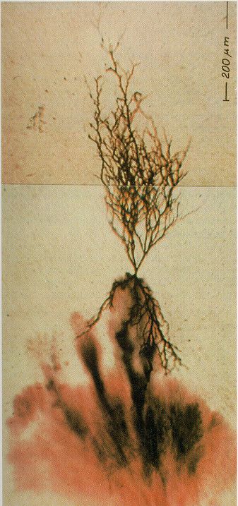
Polymers 2019, 11, 24                                                                                     2 of 60

butylene) with microcrystalline wax using special manufacturing techniques for mass-impregnated
non-draining cables above 33 kV.

      Figure 1. Different types of power cables used for electricity transmission and distribution.

     By using polymers such as polyethylene (PE), ethylene-propylene rubber (EPR) or ethylene-
propylene-diene-monomer rubber (EPDM), it was possible to obtain high and very high voltage cables
(Extra High Voltage Cables EHVC), with a low level of partial discharges, easy maintenance and
remarkable longevity. The various process steps for the production of cables containing thermoplast-
based insulations are provided in Figure 2.

      Figure 2. Typical process steps for the production of (a) wires, (b) power cables and (c) armour power
      cables employing thermoplast-based polymers as insulation. Redrawn and adapted from reference [5].

     PE was the most suitable insulation material (comprising low permittivity and high electrical
breakdown strength) in the cables production in the late 1960s and early 1970s [4]. However, PE suffers
from two major drawbacks: (i) the limitation of the maximum operating temperature, which is around
70 °C and (ii) the necessity to add antioxidants in order to avoid deterioration of the polymer-based
insulation. Taking into consideration these aspects, a new solution was found by crosslinking of PE
(yielding XLPE), which improved both, thermal resistance and ageing stability of the material due to
the formation of the 3D network. The crosslinking additives such as dicumyl peroxide should not
degrade the electrical performance of the crosslinked material [4]. Initially, cables based on XLPE were
manufactured on continuous vulcanization lines, using steam for heating and pressurizing production
stages and water under pressure for cooling. Later, it was found that the presence of steam during the
Polymers 2019, 11, 24 3 of 60
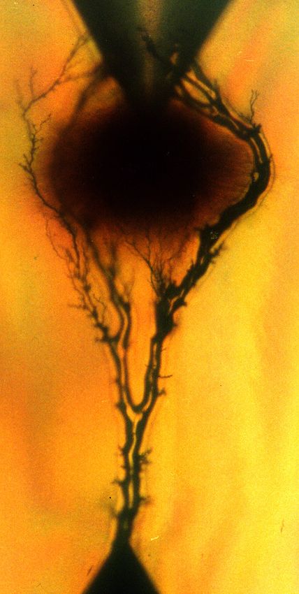
crosslinking process introduced a high level of moisture in the cable insulation, resulting in the
formation of microvoids in which electrical and/or water trees were developed, resulting in premature
breakdown of the insulation. Hence, steam was removed from the production process. A new
manufacturing process was developed involving electrical heating and pressurizing with dry nitrogen
in a continuous vulcanization line. At that time, water was still used for cooling but was later
eliminated from any stage of the process and generally removed as cooling method. Since the 1980s,
the failure rates of XLPE cables have decreased significantly by the introduction of these new
production techniques [4]. Since then, the development of XLPE for LV, HV and EHV cables with
enhanced insulation quality and properties has resulted from the production of materials with fewer
impurities as well as the reduction of negative effects generated by the presence of contaminants and
by-products of the radical crosslinking. Other approaches involve the introduction of special tree-
retardant grades of XLPE, development of colorants for the cable cores, improvement of the
compatibility between XLPE and semiconductive materials for cable screens by reduction of the size
of carbon black particles and the elimination of ionic contaminants [1,4].
Nowadays, XLPE cables are commonly applied but it becomes more and more difficult to
improve the insulation quality, mainly due to high costs involved in the production of purer materials,
which stimulates the demand for exploring other possibilities such as polymer-based nanocomposites
for obtaining the targeted improvements. While paper-insulated and oil-filled cables for AC and DC
applications are very easy to be used, conventional AC-XLPE insulated cables cannot be employed for
DC because the electrical conductivity varies with temperature and electric field and, in particular,
due to space charge accumulation [4]. For underground power cables insulation, other copolymers of
ethylene and propylene (EPR) and terpolymers of ethylene, propylene and a diene component (EPDM)
are typically applied [6]. They are highly filled and opaque elastomers due to their chemical and
physical properties (e.g. sensitivity to heat, oxidation, ozone and weather, insolubility in many polar
solvents, etc.). EPR and EPDM are flexible even at low temperatures (amorphous forms of EPR) and
exhibit a certain level of tree retardancy, however at the drawback of some electrical properties (i.e.
higher dissipation factor) [6].
Today, on-going research activities aim at the application of new polymer materials with or
without nanoparticles (e.g. LDPE/metal oxides nanocomposites containing additional voltage
stabilizers), processed by modern methods, which are very promising materials for the future of cables
insulation for DC and AC applications.
This publication provides a review of the most important thermoplast-based nanocomposites (i.e.
based on LDPE, HDPE, XLPE) used as power cables insulation, starting with their chemical structure,
addressing their electrical properties and establishing structure-property-relationships. Particularly
for cables insulations based on nanocomposites, the critical factors, which are contributing to the
degradation or improvement of the electrical performance under stress, are discussed, with a
particular focus on the influence of nanofillers and additives on the electrical properties of the cables’
insulation.
2. Critical Challenges of Polymer-based Nanocomposites in Industrial Applications
The replacement of LDPE (thermoplastic polymer) with XLPE (thermosetting polymer) enhanced
the thermomechanical properties of power cable insulations. Due to the crosslinking process, the
thermal stability, and, hence, the long-term operation in service, was significantly improved from 70
to 90 °C [7]. XLPE is being able to withstand even short circuit conditions for a few seconds with
conductor temperatures over 200 °C [8]. However, in the case of XLPE, the modulus is reduced by
several orders of magnitude at operating temperatures between 90 and 100 °C [9]. Power cable
insulations with low modulus are prone to irreversible mechanical damage during operation [10].
Currently, conventional XLPE is at the limit of capabilities, both in terms of purity (which influences
the electrical properties, especially the electrical conductivity [11]) and thermal stability (which
determines the maximum operating temperature). In order to obtain insulations with higher operating
temperatures, which allow higher current densities through conductors, there are two important
directions. On the one hand, PE could be replaced by other polymers such as EPR/EPM, PP and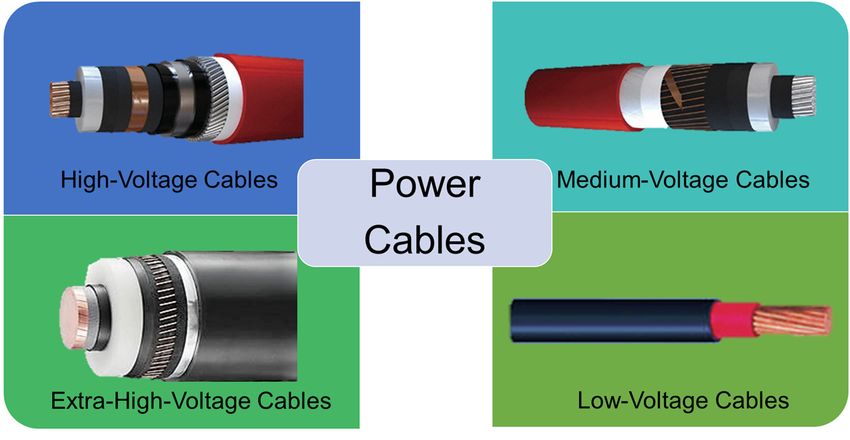
Polymers 2019, 11, 24                                                                                4 of 60

copolymers of PE and PP. In particular, the P-Laser cable represents a breakthrough in power cable
systems; it is based on the high-performance thermoplastic elastomer HPTE [12]. On the other hand,
nanocomposites based on PE or PP and organic or inorganic fillers can be used. Nanoparticles have a
larger interfacial area compared to microsized particles, which strongly influences and determines the
properties of nanocomposite materials, even at low volume concentration of such fillers (Figure 3) [13–
16]. The performance of polymer-based nanocomposites is affected by particle agglomerations since
nanoparticles have a strong tendency to aggregate (in particular if polar particles such as silica are
dispersed in a non-polar polymer matrix such as PE). In order to avoid agglomeration and to maintain
the stability of the nanoparticles within the polymer matrix, they are often surface-functionalized
[14,17]. Carefully tailored interfaces of the incorporated nanoparticles enable the preparation of
insulating nanocomposites with properties that exceed those of HVDC cables (from 320 to 800 kV),
which are applied in industry nowadays.

      Figure 3. Schematic representation of polymers nanocomposites used for power cable insulation and
      the influence of the interface on their properties.

      Although XLPE technologies are widely adopted and expected to be continuously used in the
future [10], the introduction of PE-based nanocomposites for power cables insulation is a solution
taken into consideration by many cable manufacturers. For commercial use, nanocomposites have to
fulfil several requirements involving improved thermomechanical and electrical properties and
sustainable economic and environmental characteristics. For AC cables and their joints, the polymeric
materials must exhibit, among other things, low electrical conductivity, tailor-made permittivity and
low loss factor, high dielectric breakdown strength, partial discharge resistance, absence of electric and
electrochemical treeing, stability at higher operating temperatures, and so forth. In the case of HVDC,
the insulating materials must meet two additional essential requirements: (i) low variations in
electrical conductivity with varying temperature and electric field intensity and (ii) low space charge
accumulation [7,18].
      The experimental studies revealed that the introduction of nanoparticles such as Al2O3, SiO2, TiO2,
MgO, ZnO, carbon black, graphene, graphene oxide and so forth, lead to a significant increase in
electrical resistivity (1-2 orders of magnitude [18]) and dielectric rigidity. A reduction of space charge
accumulation and an increased resistance to the action of partial discharges as well as electric and
water treeing were also observed. In addition to choosing the type and concentration of the particles,
the properties of the nanocomposites can be conveniently adjusted by surface modification of the
nanoparticles [19]. Generally, the effect of nanoparticles on reducing the electrical conductivity values
and space charge accumulation is stronger if their surfaces were covered or treated by, for example,
chemical modification. For example, in the case of LDPE nanocomposites with silane-coated Al2O3
nanoparticles (50 nm in diameter), the electrical conductivity dropped 50 times to that of LDPE. The
greatest reduction in conductivity by two orders of magnitude was achieved by using a treatment with
n-octyl-bearing silanes [20]. It should be noted that the introduction of nanoparticles in order to
improve selected properties might adversely affect other properties of the composites. For example,
the introduction of carbon black CB in LDPE causes a reduction of space charge injection and field
distortion but can decrease the DC breakdown strength of the nanocomposite (the dielectric
permittivity and dielectric loss remaining adjacent to LDPE without CB) [21].
      The maximum value of space charge density accumulated in HVDC insulation must be relatively
low in order to ensure higher reliability and long-term life performance [22]. In this case, the maximum
electric field must be below the threshold for space charge accumulation [22,23]. In fact, for all the
Polymers 2019, 11, 24 5 of 60
simulations on the behavior of HVDC cables, it was considered that the cables operate below the
threshold for space charge accumulation (the cables are space charge free), except for the charge
distribution that is the result of a temperature gradient in the insulation [22]. As mentioned above, this
can be accomplished by introducing nanostructured materials based on XLPE filled with SiO2 or MgO
nanoparticles [24]. On the other hand, the presence of moisture leads to a deterioration of the electrical
properties of polymer-based nanocomposites (in particular, reduced breakdown strength and
increased losses) [25–27]. In order to reduce the influence of humidity, a treatment of the nanoparticles
can be performed, as shown in literature for MgO nanoparticles [28]. Increasing the moisture resistance
of nanoparticles is due to a covalent attachment of functional silanes, which is carried out as an
intermediate step after a low-temperature thermal decomposition of Mg(OH)2. It was found that
moisture-resistant MgO nanoparticles retained their phase/structure even after extended exposure to
humidity and that the addition of these nanoparticles in 1 wt % quantity into a LDPE matrix resulted
in a significant increase of the electrical resistivity [28].
The use of PE based nanocomposites for commercially available high-voltage cable insulations is
still in its infancy. This is due to, among other things, reduced quantities of nanodielectrics and the fact
that the improvements of certain properties of these materials (electrical, thermal properties, etc.) are
not always valid for other properties (mechanical properties, etc.) [29]. However, the realization of the
first XLPE nanocomposite cables insulation (XLPE with MgO) should be emphasized, namely the ±
250 kV Hokkaido-Honshu LCC HVDC cable link in 2012 [30–32] and the ± 400 kV ones, which will be
put into operation in a project connecting England and Belgium in 2019 [18]. The effect of MgO on
reducing the electrical conductivity is more pronounced than that of SiO2 because MgO has a higher
relative permittivity of εr = 9.8 compared to that of SiO2 of εr = 3.9 [18]. It should be noted that the
documentation regarding the space charge behavior or mitigation on production-size transmission-
class HVDC extruded cables are not yet available [24]. It should be evidenced that a combination of
the data availability regarding the applications of nanocomposites and the commercial availability of
ultra-clean XLPE enables the future development of HVDC cables with ultra-high voltage rating [33].
In the case of DC cables junctions with two polymer layers, it is also necessary to consider the
reduction or even cancellation of superficial charge accumulated in their interfaces. For this purpose,
XLPE and nanocomposite layers of EPDM with SiC can be used [34]. It should be noted, however, that
the accumulated charge density increases upon the application of voltage and then decreases until
cancellation [34]. The introduction of nanoparticles into PE can also lead to an improvement of the
thermal conductivity of cable insulation, an important requirement for reducing their thermal ageing.
For example, in the case of LDPE and polyhedral oligomeric silesquioxanes (POS) nanocomposites, an
increase in thermal conductivity was achieved by approx. 8%, while the dielectric rigidity remained
unmodified and the corona discharge resistance increased [35]. In addition, the introduction of boron
nitride (BN) particles into LDPE resulted in an increase of the thermal conductivity of up to 1 Wm1∙K1
at a filler loading of 40 wt % [36].
Although a series of PE-based nanocomposites with electrical and/or thermal properties superior
to the unfilled polymer have been achieved, the introduction of these new materials into the current
production of power cables requires the performance of extensive testing and life modelling to
investigate both the space charge trapping properties and the long-term life performance, in order to
define suitable levels for the design field and reach cost-effective designs associated with the desired
life and reliability levels [22].
3. Polymers for Power Cable Insulations
In the field of MV and HV cables, cable jackets and semiconducting layers, extruded polymers
are commonly used. Benefiting from low raw material and processing costs together with high
reliability and adequate material performance, polyethylene (PE) and, in particular, crosslinked
polyethylene (XLPE) are widely applied [37]. Other polyolefins such as syndiotactic polypropylene
(PP) have been reported to exhibit good insulating properties but the high cost of the material hinders
widespread application [38]. Along with homopolymers, also blends of different types of polyolefins,
copolymers such as ethylene propylene rubber (EPR) and ethylene propylene diene rubber (EPDM)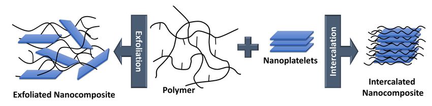
Polymers 2019, 11, 24                                                                                           6 of 60

are employed as extrudable dielectric materials. The chemical structures of selected polymers are
shown in Figure 4.

                                      Si(OMe) 3

               n                 n          m               n               n      m             n      m
                                                                                                            o

         PE             vinyl silane grafted PE        PP                 EPM                        EPDM

      Figure 4. Chemical structure of polymers used as extrudable dielectric materials. PE: polyethylene; PP:
      polypropylene; EPM: ethylene propylene rubber; EPDM: ethylene propylene diene monomer rubber.

3.1. Power Cable Insulations based on Polyethylene (PE)
     Polyethylene comprises a saturated carbon-carbon backbone and is a typical thermoplast, which
means that the polymer melts when heated above its melting point. The type of branching, the crystal
structure and the molecular weight of the polymer chains mainly govern the material properties of PE
(Figure 5). The most prominent types are low-density polyethylene (LDPE) with a considerable
number of short-and long-chain branching, linear low-density PE (LLDPE) with a significant degree
of short branches and high-density PE (HDPE) with a low amount of branching. LLDPE and HDPE
are produced by coordination polymerization in the presence of selected catalysts (e.g. Ziegler-Natta,
Philips, metallocenes), which leads to controlled branching and molecular weight of the polymer
chains. In contrast, LDPE is obtained by free-radical polymerization at high pressures and high
temperatures without the use of any catalyst, resulting in polymer structures with random short- and
long-chain branching. Thus, the material costs of LDPE are much lower than LLDPE or HDPE, which
makes it, in conjunction with the low dielectric constant, the low dielectric loss and the high
breakdown strength, an ideal candidate for extrudable dielectric materials [39].

                        Figure 5. Schematic representation of the structures of varying types of PE.

     Previous work has shown that the electrical properties of LDPE such as dielectric strength and
space charge formation are influenced by its crystalline structure [40,41]. LDPE is a semi-crystalline
polymer typically containing 45–55% crystalline domains in the form of lamellae, which are
surrounded by the amorphous bulk phase. The size of the crystalline domains can be controlled by the
parameters of the extrusion process. While high cooling rates result in smaller domains and lower
degrees of crystallinity, thermal annealing yields larger domains in conjunction with a higher amount
of crystallinity. The annealing and cooling steps of the extruded LDPE insulation are carried out under
high pressure and under inert conditions in order to reduce the formation of voids. Particularly in the
production of cable insulation, higher crystallinity and smaller domains are favoured as the final
product correspondingly shows smaller voids and improved ductility. Along with the crystalline
regions, the amorphous bulk has also a distinctive influence on the electrical properties of LDPE.
Dissado and Fothergill [42] demonstrated that charge transport mainly occurs within the amorphous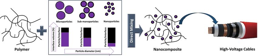
Polymers 2019, 11, 24                                                                                     7 of 60

regions of LDPE. Khalil [43] has shown that the initial morphology of PE can change during thermal
cycling in conjunction with DC conductivity leading to a distinctive increase in conductivity.
     The electrical behavior of PE is further influenced by impurities, voids and ageing (e.g. carbonyl
moieties formed by oxidation of the polymer chain), which are expected to induce space charge
accumulation leading to a local heating that can result in electrical breakdown of the insulation
material [42].

3.2. Power Cable Insulations based on Crosslinked Polyethylene (XLPE)
      Aiming at an enhanced thermal and chemical resistivity in combination with improved
mechanical properties (in particular at high filler loading) and ageing behavior, LDPE may be
crosslinked (XLPE). Due to the crosslinking of the polymer chains, the operational temperature can be
increased from 75 to 90 °C. Previous studies [39] report that XLPE is stable at 130 °C during 36 h.
However, if the temperature of the conductor reaches 250 °C (e.g., during a short circuit), the XLPE-
based insulation degrades within seconds [44].
      The most common crosslinking mechanism originates from the addition of radical initiators such
as organic peroxides, which undergo homolytic bond cleavage during the extrusion process and
initiate radical-induced crosslinking of the polymer chains (Figure 6). Curing with dicumyl peroxide
enables safe processing up to 120 °C, while the processing temperature can be increased to 150 °C
using 2,5-bis-(tert-butylperoxy)-2,5-dimethylhexane. Thermal cleavage of dicumyl peroxide yields
several by-products involving methane, acetophenone and cumyl alcohol. The curing of the extruded
insulation is usually performed at high pressures in the range of 12–20 bar to avoid the formation of
voids from such gaseous by-products. During the production of cables, the XLPE-based insulation is
kept in a fan-forced oven at elevated temperature (70 °C) to remove the majority of these by-products
(particularly methane, which is highly flammable and forms explosive gas mixtures with air) [39].

        Figure 6. Thermal curing of PE with organic peroxides. Redrawn and adapted from reference [45].

     Another well-established approach involves the crosslinking of a chemically modified PE in the
presence of a catalyst and moisture after the extrusion process (Figure 7). The chemical
functionalization of the PE is carried out by grafting vinyl silanes onto the polymer chain during the
extrusion process. Small amounts of an organic peroxide are added to facilitate the grafting process
[46]. Modified PE grades, which are produced by copolymerizing ethylene and 3-
vinyltrimethoxysilane, are commercially available [47]. After the extrusion of the modified PE, the
cables are stored in a water bath at high temperatures or in a steam chamber to induce the crosslinking
reaction. The crosslinking reaction, which involves a hydrolysis reaction followed by a condensation
of the generated silanol groups, is catalyzed by dibutyltin dilaurate.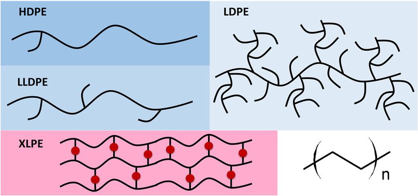
Polymers 2019, 11, 24                                                                                      8 of 60

             Figure 7. Thermal curing of PE with siloxanes. Redrawn and adapted from reference [48].

     In addition, crosslinking of LDPE is also obtained under high energy radiation such as electron
beam and gamma radiation generated from a Co60 source [49–51]. The crosslinking is based on a free-
radical mechanism involving the extraction of a hydrogen atom from the polymer chain by the
accelerated electrons or by the electromagnetic wave (Figure 8). Polymer radicals are formed, which
recombine under the formation of a covalently bound crosslink site. In order to increase the degree of
crosslinking, sensitizers such as acrylates may be added to the polymer. The radiation induced
crosslinking is carried out after the extrusion of the insulating layer at ambient conditions. Aiming to
avoid a rapid temperature increase during crosslinking, the extruded cables are passed through the
electron beam of electron radiation over several cycles until the targeted exposure dose has been
reached. In general, crosslinking of PE with high energy radiation has the disadvantage of high
processing costs, as special radiation sources at high investment costs are required.

       Figure 8. Crosslinking of PE with high energy radiation. Redrawn and adapted from reference [52].

3.3. Power Cable Insulations based on other Classes of Polymers
     Along with XLPE, ethylene-propylene rubbers have been the most popular dielectric materials in
extruded cables over the last decades [39]. They can be divided into two main classes: (i) ethylene-
propylene rubber (EPM or also EPR) as a copolymer of ethylene and propylene and (ii) EPDM as
terpolymer, which consists of ethylene, propylene and diene components such as dicyclopentadiene,
ethylidene norbornene, and/or vinyl norbornene.
     EPR is a fully saturated and nonpolar polymer with high temperature stability and high resistivity
towards oxidation and polar solvents. EPR congeners with a low ethylene content are amorphous and
easy to process but typically have inferior mechanical properties. In contrast, EPR types with a high
ethylene content are semi-crystalline and have improved mechanical properties. Similar to LDPE, EPR
may be crosslinked with organic peroxides [53,54].
     EPDM has a fully saturated polymer backbone but additionally comprises unsaturated carbon-
carbon bonds in the side-chains, which change the reactivity of the polymer in crosslinking reactions.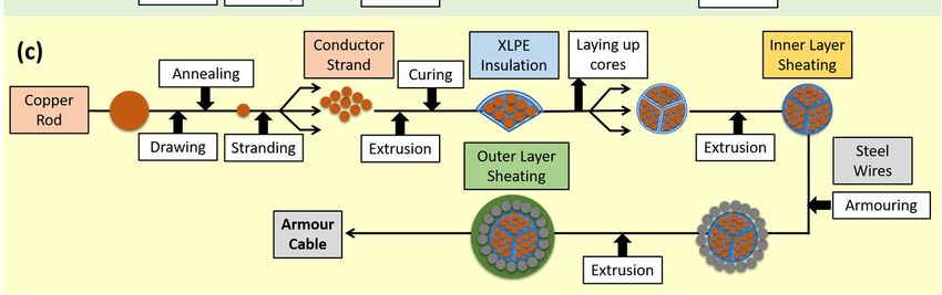
Polymers 2019, 11, 24                                                                                          9 of 60

In addition to curing with peroxides, EPDM can be also cured by sulphur vulcanization involving the
unsaturated carbon-carbon bonds. While the electrical properties of sulphur- and peroxy-crosslinked
EPDM are comparable, it was demonstrated that sulphur-cured EPDM insulations show poor
performance after long-term immersion in hot water. In extruded EPM or EPDM insulations, the
polymer content is typically in the range of 50%, as a high amount of inorganic fillers (e.g. clay, talc,
silica, and alumina) is added to yield smooth surfaces and sufficient mechanical strength of the final
insulation.

4. Nanocomposites for Power Cable Insulations
     In order to tune the electrical and mechanical properties of extruded polymers, the addition of
selected nanosized inorganic and organic fillers has gained increased attraction. These so-called
nanocomposites benefit from (i) the low weight, (ii) the easy processing and (iii) shaping of the polymer
matrix as well as (iv) the salient properties of the incorporated nanoparticles, which are substantially
different to their micrometer-scaled counterparts. At a given volume, nanosized fillers have a
distinctively larger surface area than microsized ones. As the chemical and physical properties of
composites are strongly influenced by the interactions between the filler and the polymer matrix,
nanofillers yield different properties than macroscopic particles of the same chemical and
morphological composition. This effect is also exploited in the cable industry and numerous studies
have been reported on the production, characterization and performance of nanocomposites as
dielectrics in cables [14,33,55,56]. The following section gives a short summary describing the types of
nanofiller and the preparation of nanocomposites following 'bottom up' and 'top down' processes
(Figure 9).

      Figure 9. Differences between 'bottom up' and 'top down' processes used in the preparation of polymer
      nanocomposites.

4.1. Fillers used in Nanocomposites
      It is well known that the high aspect-ratio of nanofillers mainly contributes to their reinforcing
efficiency. Depending on the geometry of the particles, three main types of fillers are distinguished
(Figure 10): (i) (spherical) particles, (ii) fibers and (iii) platelets [57,58]. In terms of fibers and platelets,
the (surficial) area-to-volume ratio is mainly governed by the first term (2/r and 2/t) of the equation,
while in nanomaterials, the influence of the second term is negligible. Thus, a change of the particle
geometry from the micro- to nanometre size changes the area-to-volume ratio by three orders of
magnitude.

      Figure 10. Three main types of nanofillers (from left to right: spherical particles, fibers and platelets),
      classified by their geometry and area-to-volume ratio. Redrawn and adapted from reference [57].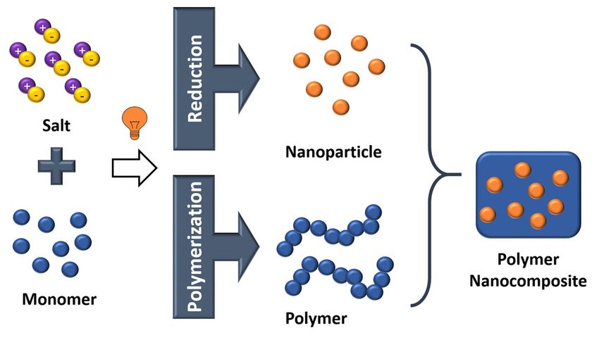
Polymers 2019, 11, 24                                                                                    10 of 60

     Along with the geometry, nanofillers may also be classified either by their chemical and
morphological structure or by their origin (natural versus synthetic and organic versus inorganic) as
shown in Table 1.
     The properties of nanocomposites are not only influenced by their geometry and type but also by
the dispersion of the filler in the polymer matrix. Nanofillers tend to agglomerate during the
preparation of nanocomposites, which compromises the electrical, mechanical and optical properties
of the final material [59]. In order to improve the dispersion of the particles in the polymer matrix and
to ensure an enhanced bonding between the particles and the polymer matrix, surface modification of
the particles is often carried out [60].

      Table 1. Examples of different types of nanofillers classified by their origin (Adapted from reference
      [61]).

           Origin                                 Selected examples of nanofillers
                  animal                                      silk, wool, hair
   natural       mineral                                        asbestos
                 cellulose                          wood, seed, leaf, fruit, stalk, bast
                                               oxides: TiO2, SiO2, Al2O3, ZnO, MgO, Sb2O3
                                                       hydroxides: Al(OH)3, Mg(OH)2
                                                    metals: Al, Au, Ag, B, Sn, Cu, steel
                 inorganic                         silicates: talc, mica, nanoclay, kaolin
                                                         salts: CaCO3, BaSO4, CaSO4
  synthetic
                                                                  carbides: SiC
                                                             nitrides: AlN, BN
                               carbon based materials: graphite fibers, nanotubes, carbon black, graphene
                  organic           natural polymers: cellulose and wood fibers, cotton, flax, starch
                              synthetic polymers: aramid, polyester, polyamide, poly(vinyl alcohol) fibers

4.2. Methods for the Preparation of Nanocomposites
     Over the last years, four main routes have been established for the successful incorporation of
inorganic nanofillers into a polymer matrix: (i) direct mixing of polymer and filler, (ii) intercalation
based on the exfoliation of, for example, layered silicates, (iii) sol-gel processes and (vi) in-situ
formation of nanofillers in the polymer matrix [59,62,63]. The simplest route involves a direct mixing
of the nanoparticles in the polymer, above the glass-transition temperature Tg or the melting point Tm
of the polymer (melt-compounding method). Alternatively, the direct mixing can be also carried in a
polymer solution (solution-mixing method). After evaporation of the solvent, the fillers are well
distributed in the polymer matrix. Direct mixing is a typical top-down process, which means that
energy is used (i.e. mixing energy) to transform a bulk material in smaller fragments until a
nanocomposite is obtained (Figure 11) [64,65].

                             Figure 11. Preparation of nanocomposites by direct mixing.
Polymers 2019, 11, 24 11 of 60
Another top-down process is the intercalation involving the exfoliation of layered silicates (Figure
12). Three different methods are typically pursued: (i) direct intercalation of polymer chains from
solution, (ii) polymer melt intercalation and (iii) intercalation of monomers followed by in-situ
polymerization [66].
Figure 12. Preparation of nanocomposites by exfoliation and intercalation. Redrawn and adapted from
reference [67].
Regarding the direct intercalation of polymer chains from solution, the layered fillers (typically
nanoclays) are dispersed into a solvent in which the polymer is soluble [68,69]. The solvent migrates
through the layers of the filler to start the exfoliation. After evaporation of the solvent, single clay
platelets are well dispersed in the polymer matrix. With respect to melt intercalation, the layered fillers
are directly mixed with the polymer melt. Due to shear forces, the exfoliation of the platelets starts
and, if the surface polarities of filler and polymer are similar, the polymer chains migrate into the
interlayer space. In terms of intercalation of monomers followed by in-situ polymerization, monomers
and selected initiators are employed [69]. The monomers intercalate into the layered filler and increase
the distance between the layers. Subsequent polymerization of the monomers leads to an exfoliation
of the filler and polymer-based nanocomposites are yielded.
The sol-gel process is a prominent example of a bottom-up approach, which involves the building
of the targeted material by the assembly of building units (e.g. atom-by-atom or cluster by cluster)
[68,70]. The sol-gel process relies on two subsequent reactions steps (Figure 13). In the first step, metal
oxides are obtained from the hydrolysis of organic metal alkoxides or esters yielding a colloidal
suspension of solid particles in a liquid phase (sol). In a second step, the hydrolyzed intermediates
start to condensate forming an interconnected network (gel) between the particles.
Figure 13. Preparation of nanocomposites by sol-gel processes. Redrawn and adapted from reference
[71].
The fourth method involves the in-situ generation of nanoparticles from metal ions by redox
reactions, which can be stimuli-triggered by a change of the pH value or by UV light (Figure 14). The
in-situ generation of the nanoparticles is usually carried out in conjunction with an in-situ
polymerization using colloidal sols with metal ions and monomers. This approach is typically
employed to obtain nanocomposites from thermosetting resins such as epoxides or photocurable
resins such as acrylates [72–74].Polymers 2019, 11, 24 12 of 60
Figure 14. Preparation of nanocomposites by UV-induced in-situ generation of nanoparticles and in-
situ polymerization of a photoreactive monomer.
4.3. Surface Modification of Fillers to be used in Nanocomposites
The homogeneous dispersion of nanosized fillers within the polymer matrix has major influence
on the final properties of the nanocomposites [59]. In particular, the surface modification of inorganic
particles has become a popular route to avoid agglomeration and cluster formation of nanofillers, since
the attachment of functional groups on the particles’ surfaces enables the controlled change of polarity
and reactivity of the particles’ surfaces. A typical example is the surface modification of carbonates or
silicates with hydrophobic fatty acids to improve the dispersibility in non-polar polymer matrices such
as polyolefins [75]. Besides the dispersibility, the particle-polymer interfaces can be tailored by
incorporating functional groups on the fillers’ surfaces. As the particle-polymer interface has a crucial
influence on the performance of the corresponding nanocomposites, surface modification techniques
have gained increased attention for tuning the mechanical and electrical performance of polymer
nanocomposites [76–79]. Pallon et al. [80] applied functional silsesquioxane coatings on MgO
nanoparticles and incorporated the functional filler in LDPE. They demonstrated that the modified
particles were homogenously distributed within the polymer matrix and, by adding only 3 wt % of the
surface-treated particles, the volume conductivity was decreased by two orders of magnitude. For the
modification of inorganic particles, different strategies are pursued involving (i) chemical treatment,
(ii) grafting reactions and other methods such as (iii) adsorption of polymeric dispersants [81].
The typical chemical surface modification reaction proceeds in one step using bifunctional organic
compounds with one group that reacts with the nanoparticles’ surfaces and a second group, which
represents the functionality of the organic shell. One well-established approach is the so-called
silanization, in which functional trialkoxysilanes such as 3-aminopropyl triethoxysilane are covalently
attached to surficial hydroxyl groups of inorganic particles (e.g. SiO2, TiO2, Al2O3, ZnO, Fe3O4) by
condensation reactions (Figure 15) [82,83]. In terms of carbon-based nanofillers such as carbon black,
fullerenes, carbon nanotubes or graphene, Diels-Alder reactions can be employed to change the surface
characteristics of the particles [84]. If the functional groups of the organic compound are not
compatible with the synthetic process, a step-wise procedure may be carried out for the modification
of inorganic particles [85].Polymers 2019, 11, 24 13 of 60
Figure 15. Covalent attachment of functional silanes on nanosized silica. Redrawn and adapted from
reference [86].
Grafting reactions represent another route to modify the surface of inorganic particles (Figure 16)
[86]. The grafting mechanism involves either (i) direct coupling of a polymer chain onto the particle
surface ('grafting onto' reactions) or (ii) immobilization of a monomer or an initiator on the particle
surface, which is followed by a polymerization of reactive monomers ('grafting from' reactions).
A convenient method for surface modification of inorganic nanoparticles involves the physical
adsorption of polymeric dispersants, which is typically used to enhance the dispersion stability of
nanoparticles in solvents [87,88]. The improved dispersion properties mainly rely on the steric
repulsive forces between the adsorbed polymer chains and the related increase in surface charges.
Figure 16. Modification of nanoparticles via (i) 'grafting onto' and (ii) 'grafting from' reactions.
5. Electrical Conductivity of Nanocomposites
5.1. General Aspects of Electrical Conduction
Electrical conductivity is an intrinsic property that quantifies the ability of materials to conduct
electric current [89,90] and can be classified in three major categories: (i) intrinsic conductivity: charge
carriers are generated based on the chemical structure of the material; (ii) extrinsic conductivity: charge
carriers are generated by impurities, which can be introduced during the fabrication process or by
dopants through specific methods; (iii) injection-controlled conductivity: charge carriers are injected into
the material through the interface between the metallic electrodes and the non-metal material.
Regarding insulators, the charge carriers’ origins for intrinsic and extrinsic conductivities are not
well distinguished; in polymeric insulators, the situation is even less well characterized and
understood. Some polymeric materials such as PE can be considered as natural nanodielectric materialPolymers 2019, 11, 24 14 of 60
with contrasting conductive crystallites and resistive amorphous regions of nanometric dimensions
[91], as it was described in section 3 (Figure 17).
Figure 17. The morphological structure of PE. Redrawn and adapted from reference [92].
In the crystalline phase of PE, intrinsic conduction is improbable due to the large band gap of
approx. 8 eV and the corresponding separation of electrons and holes [91]. Excluding any material
defects caused by impurities, conduction in PE can only originate from extrinsic charges introduced
by the injection process. Hole conduction commonly appears in PE, which suggests that hole injection
at the anode occurs more easily compared to the electron injection at the cathode [91]. However, the
crystalline regions in PE are surrounded by amorphous regions and the transfer of electrons and holes
between them is likely to be hindered. Holes enclosed to the valence band will move along the
crystallites’ chain paths and will become trapped in the interphase between them and the amorphous
regions. However, the transition of holes through this interphase will occur by tunnelling due to a
super-exchange between donor and acceptor hole traps [91]. Amorphous regions in PE are considered
to have high concentrations of traps introduced by impurities and additives, which may be polarized
and maybe even move through them. Hence, extrinsic conduction (ionic transport) is more likely to
occur in the amorphous phase [93].
Lewis et al. [91] concluded that the incorporation of oxide nanoparticles in PE causes a strong
decrease of the local hole inter-lamella transition rate. They assumed that the tunnelling of holes
between lamellae through the amorphous phase in the neighborhood of a particle was strongly
influenced by the embedded particle and its surrounding interface. The magnitude of affected
transitions, which would lead to macroscopic decrease of mobility and conductivity, would depend
on the concentration of nanoparticles embedded within the polymer matrix. In agreement with this
conclusion, several experimental results regarding the electrical conductivity of thermoplastic
nanocomposites based on polyethylene used as power cables insulation will be presented in the
following sections.
5.2. Conductivity of Nanocomposites based on Polyethylene (PE)
The incorporation of various oxidic nanoparticles (e.g. Al2O3, SiO2, TiO2, MgO, ZnO, etc.) in PE
delivers advantages such as a significant reduction in electrical conductivity for a certain range of
nanoparticle concentrations (usually between 0 and 5 wt %). This reduction reflects the ability of the
polymer matrix to incorporate the nanoparticles within the inter-lamellae spaces. Above this limit, the
excess of nanoparticles is likely to be incorporated in inter-spherulite regions, which does not directly
influence the hole conduction from inter-lamellae crystallites [91].Polymers 2019, 11, 24 15 of 60
Hoang et al. [94] analyzed the bulk conductivity of LDPE and its nanocomposites with uncoated
magnesia (MgO) and alumina (Al2O3). The investigations were performed on thin films prepared by
thermal extrusion at 150 °C from a dried powder mixture of LDPE, nanoparticles and antioxidant (0.02
wt % of Irganox 1076). Two types of nanocomposites based on LDPE filled with 1 and 3 wt % of Al2O3,
as well as five types of LDPE filled with 0.1, 1, 3, 6 and 9 wt % of MgO were prepared. The DC
conductivity measurements were carried out at an applied electric field of approximately 30 kVmm1,
for 11 h. The measurements were conducted at isothermal conditions (room temperature, 40 and 60
°C) by placing the electrode system with the sample inside to a grounded oven (Figure 18a). DC
conductivity values were computed from the charging current data registered during 11 h of
measurements (Figure 18b). The results on LDPE samples agreed with the data reported in literature
[95]. In the case of LDPE/Al2O3 samples, the reduction in DC conductivity was proportional with the
filler concentration increasing up to 3 wt %. For nanocomposites based on LDPE and MgO, a threshold-
like behavior was observed around a nanofiller content of 3 wt % (Figure 18b). If the filler concentration
exceeded 3 wt %, further loading with nanoparticles caused a negative effect. This change in the
electrical conductivity behavior can be explained by the agglomeration of nanoparticles in the polymer
matrix during the manufacturing of the samples [94]. This effect was also reported by Ishimoto et al.
[96], Masuda and Murakami et al. [97,98], who described a decrease of electrical conductivity of more
than one order of magnitude and a threshold of nanofillers content of approximately 2 wt %.
(a) (b)
Figure 18. (a) Schematic representation of the test setup for DC conductivity measurements; (b)
Variations of the DC conductivity with the filler concentration of the analysed nanocomposites.
Reprinted from reference [94].
Pleşa analyzed the absorption currents and computed the relative DC volume resistivity of
nanocomposites based on LDPE with different types of inorganic nanofillers (SiO2, TiO2, Al2O3) and
various concentrations (2, 5 and 10 wt %) [99]. For better compatibility and dispersion of nanoparticles
within the polymer, the surface of the nanofillers was treated with maleic anhydride. All
measurements were performed at ambient temperature of 27 °C and relative humidity of approx. 50%
(Figure 19). Noteworthy, the absorption currents decrease over time as a result of the reduction of the
charge carrier’s concentration corresponding to bound charges (electric dipoles) and space charge. On
the other hand, according to the nanocomposite models presented in literature [100–102], the
introduction of nanoparticles into the polymer facilitates an increase in the concentration of the electric
dipoles (i.e. especially inside the nanoparticles and/or inside the polymer-nanoparticle interfaces) and
also an accumulation of space charge due to the huge area of polymer-nanoparticles interfaces. In this
case, polarization and space charge components of absorption currents increase with enhanced
concentration of nanofillers, except for LDPE with 2 wt % of nano-TiO2 that showed lower values
compared with all the other types of analyzed materials (Figures 19a,b).Polymers 2019, 11, 24 16 of 60
(a) (b)
Figure 19. Variations of absorption currents on time for: (a) LDPE nanocomposites with 2 wt % of
different types of inorganic nanofillers and (b) LDPE nanocomposites with 2 and 5 wt % of nano-TiO2.
Reprinted, with permission by the author, from reference [99].
In order to explain the variations of the currents, models of the nanocomposites’ structure were
used. Starting from the structural models proposed by Tanaka et al. [100] as well as Lewis [103], a new
model for nanocomposites based on LDPE with spherical inorganic fillers was developed (Figure 20)
[99]. It was considered that the interface was formed by three distinct regions: a bonded first layer, a
bound second layer and a loose third layer, with an electric double layer overlapping these three layers.
The polymer is in an intimate contact with the nanoparticle surface within the first layer, while the
second layer represents an interfacial region. The third layer interacts superficially with the second
layer and the properties of this region are supposed to be similar to the polymer matrix.
Figure 20. Schematic representation of an interfacial LDPE-nano-SiO2 structure. Reprinted, with
permission by the author, from reference [99].
In case of LDPE nanocomposites with 2 wt % of nano-TiO2, a decrease of absorption currents
compared to unfilled LDPE values was registered (Figure 19a). This behavior could be explained byPolymers 2019, 11, 24 17 of 60
the presence of crosslinked polymer in the third layer of the polymer-nanoparticle interface, which
reduces the mobility of space charges through the material structure and may lead to a decrease of the
space charge component of the absorption current values. Between the end groups of the polyethylene
chains from the second layer of the interface and the surface of the functionalized inorganic
nanoparticles, hydrogen bridges are formed that reduce the mobility of polymer chains and decrease
the polarization component of the absorption current. Tanaka et al. [100] stated that within the
intermolecular regions of the interface layers, the introduced traps were distributed as follows: deep
traps in the first and second layer and shallow traps in the third layer. By increasing the filler
concentration over a certain limit (i.e.> 2 wt % in the case of LDPE/nano-TiO2) inside the polymer
matrix, the overlapping zone of filler-polymer interfaces increases, too (i.e. similar with the model
presented in Figures 20, 21a and 21b). By applying an electric field, the electrical conduction can occur
either by charge carriers jumping on the shallow traps from the interfaces, overlapping the neighbor
nanoparticles or by tunnelling [99], when the distance between the traps is below the minimum
threshold tunnelling, leading, in overall consequence, to an increase in space charge components of
the absorption currents (Figure 19b).
2 wt % LDPE/nano-SiO2
5 wt % LDPE/nano-SiO2
10 wt % LDPE/nano-SiO2
(a) (b)Polymers 2019, 11, 24 18 of 60
Figure 21. (a) Two neighbor nanoparticles within LDPE composites for different filler contents; (b) 3D
electrostatic model of nanocomposites based on LDPE with nano-SiO2 in different concentrations.
Reprinted, with permission by the author, from reference [99].
The volume resistivity can be calculated according to equation (1):
S U
= ∙ (1)
d I
in which ρv is the volume resistivity (Ωm), S the electrode surface (m2), U the applied voltage (V), I
the average current after 4000 seconds starting from the voltage application (A) and d the sample
thickness (m). It was observed that the resistivity values depend on the type and concentration of
nanoparticles and decrease compared to unfilled LDPE (Table 2). With respect to LDPE with 2 wt %
of nano-TiO2, the DC relative volume resistivity increases by 0.07 percent points compared to unfilled
LDPE.
Table 2. DC relative volume resistivity of nanocomposites based on LDPE with 2 (or 5) wt % of different
types of inorganic fillers. Adapted with permission by the author from reference [99].
Nanocomposite Filler content DC relative
(type of filler) (wt.-%) resistivity
Pure LDPE 0 1
LDPE/nano-SiO2 2 0.54
LDPE/nano-Al2O3 2 0.16
LDPE/nano-TiO2 2 1.07
LDPE/nano-TiO2 5 0.33
In order to increase the DC electrical properties of XLPE insulation materials, Yan et al. prepared
nanocomposites based on XLPE with different loadings of carbon black (CB) by the melt-blending
method [104]. The space charge distribution was analyzed together with the dependence of DC
electrical conductivity γ on the electric field E at several temperatures T (Figure 22). For low electric
fields, a non-linear dependence of γ and E exists, concomitant with a significant increase in
conductivity with increasing T. For E < 20 kVmm−1, the electrical conductivity of XLPE/CB is almost
constant; however, if the temperature increases over 30 °C, γ(E) decreases. This study shows that the
presence of CB in XLPE can inhibit the space charge accumulation and the electric field distortion,
improving the DC conductivity of XLPE/CB nanocomposites.Polymers 2019, 11, 24 19 of 60
Figure 22. Electrical conductivity [γ(S/m)] variations of XLPE and CB/XLPE nanocomposites at
different temperatures. Reprinted, with permission by IEEE, from reference [104].
The correlation of the electrical conductivity with the content of nano-SiO2 particles in XLPE was
analyzed by the CIGRE Working Group D1.24 [105]. It was concluded that the addition of fumed nano-
SiO2 to XLPE reduced the DC conductivity of the nanocomposites. This behavior supports the
mechanism describing nanofillers as charge carrier traps; it may be argued that functionalization may
strengthen their function. Wang et al. [106] analyzed the electrical resistivity of nanocomposites based
on XLPE containing different concentration of nano-TiO2 (i.e. 1, 3 and 5 wt %). It was found that their
volume resistivity was higher compared to pure XLPE and increased with the filler concentration. This
behavior was referred to the large number of traps introduced in nanocomposites by the fillers, which
capture the charge carriers and prevent the movement of carriers within them. Murata et al. [107]
investigated the volume resistivity and space charge distribution in nanocomposites obtained by
mixing XLPE with MgO nanofillers. Four types of materials were analyzed: conventional XLPE
insulation for AC cables (XLPEC), nanocomposites obtained by mixing XLPEC with nano-MgO
(XLPEC/MgO), a special type of XLPE with a lower degree of crosslinking by-products compared to
XLPEC (XLPES) and nanocomposites obtained by mixing XLPES with nano-MgO (XLPES/MgO). It was
concluded that the presence of by-products (that decrease the volume resistivity) and of nano-MgO
(that increases the volume resistivity) acted synergistically within XLPE-based nanocomposites,
converting them into excellent materials for DC power cables insulation.
According to the experimental studies presented herein above, two types of PE-based
nanocomposites are recommended for power cables, those with low conductivity for insulations
(including inorganic particles) and those with increased conductivity for semiconductor layers
(including carbon black fillers).
6. Permittivity and Loss Factor of Nanocomposites
6.1. General Aspects of the Complex Dielectric Permittivity
Synthetic polymers are complex molecules comprising a huge number of covalently bound atoms
within the macromolecular chains, yielding numerous possible conformations of the individual
macromolecular chains in space and time [108]. Due to this large number of conformations, most of
the polymers have properties depending on the chain flexibility, the end-to-end vector of the chain,
the mean-square dipole moment per molecule and so forth. Correspondingly, their behavior in
solution and/or in solid state is analogously complex. Besides systems composed of linear
macromolecules, a comprehensive variety of the molecular architectures additionally exists (e.g.
branched and hyperbranched polymers, cyclic macromolecules and oligomers, polymers with star-
shaped and comb-like structures, copolymers, dendrimers, etc.), which can cause new morphologies
in the dense state of these molecules (i.e. phase- or microphase-separated structures).
Since Debye published the theory of dipolar relaxation in 1929 [109], the study of the interaction
between electromagnetic radiation and (soft) matter, which is of crucial importance in fundamentalPolymers 2019, 11, 24 20 of 60
and applied science, has been applied to dielectric spectroscopy. This experimental technique is very
useful for studying the conformation, the structure and the dynamics of polymers (i.e. dipolar
processes) and to evaluate the behavior of polymeric systems over a large range of frequencies and
temperatures. Dipolar processes include very low frequency processes (i.e. electric charge transport),
Maxwell-Wagner polarization processes (i.e. charge trapping at interfaces) and relaxation processes due to
the motion of dipoles groups (i.e. dipole reorientation) [93].
For dielectric spectroscopy studies, one key parameter is the relative complex dielectric
permittivity ∗ (Equation 2) [108]:
ε* (f) = ε' (f) − iε'' (f) (2)
in which represents the real part of complex relative permittivity and the imaginary part of the
relative permittivity, the so-called loss part.
The complex relative permittivity is defined as a factor between an outer alternating electric
field ⃗ ( ) and the induced electric polarization of the medium (Equation 3):
P⃗(f) = χ* ε0 E⃗(f) (3)
in which * = *(f) 1 is the complex electric susceptibility of the material and 0 = 8.851012 Fm1 is the
vacuum permittivity.
The complex relative permittivity is a material property depending on frequency, temperature,
pressure and structure of the material. According to statistical mechanics, both quantities, namely ε´
and ε´´, have a physical interpretation: is related to the energy stored reversibly within the material
and is related to the energy dissipated within the material. In dielectric relaxation spectroscopy,
the dissipation factor tan = ⁄ , in which is the phase angle between the applied voltage and
the resulting electric current, is one parameter for the discussion of the electrical performance of
polymer-based materials [108].
The addition of nanoparticles into polymers considerably changes the dielectric behavior due to
the formation of interaction zones within the nanocomposites [93]. Correspondingly, there has been a
steadily growing interest over the last two decades to analyse these materials, which are referred to as
nanodielectrics in this context. In the following section, selected results are presented regarding the
permittivity and loss factor of thermoplastic polymer nanocomposites used as power cables insulation
(LDPE, XLPE, etc.).
6.2. Permittivity and Loss Factor of Nanocomposites based on Polyethylene (PE)
A huge number of studies have reported improved dielectric properties of thermoplastic
nanocomposites with inorganic nanoparticles compared to the unfilled polymer [69,110–116], which
render these nanocomposite materials as interesting candidates for high-voltage applications. The
dielectric behavior of thermoplastic nanocomposites systems based on LDPE containing different
types and contents of nanofillers have been analysed and presented in the literature.
Pleşa et al. analyzed the behavior of unfilled LDPE and silica-filled LDPE samples [99].
Nanocomposites with different contents of nanofillers ranging from 0 to 10 wt % were prepared and
characterized at different temperatures in the range from 300 to 350 K and frequencies from 10−2 to 106
Hz (Figure 23). The activation energy wa was estimated, and correlations with the polarization
mechanisms were found. The imaginary part of the complex permittivity ’’ was determined as the
product of the real part of complex permittivity ’ and the loss factor tan. It was assumed that the
conduction losses were substantially lower than the polarization losses by deformation and
orientation. In the case of unfilled LDPE (Figure 23a), peaks in the frequency range from 101 to 103 Hz
were shifted to higher frequencies upon temperature increases. With an increasing concentration of
SiO2 nanoparticles in the polymer matrix (Figures 23b to 23c), a shift of the ’’ peaks towards lower
frequencies as well as their intensification compared to the base polymer were observed. For example,
in case of the nanocomposites containing 5 wt % of nanoSiO2 (Figure 23b), the peaks were in the range
of 101 to 101 Hz. When the concentration of the nanoparticles was increased, the frequency domain
into which the peaks shifted increased to 103 Hz in the case of nanocomposites with 10 wt % of nano-You can also read