FireSim: FPGA-Accelerated Cycle-Exact Scale-Out System Simulation in the Public Cloud - Sagar Karandikar
←
→
Page content transcription
If your browser does not render page correctly, please read the page content below
2018 ACM/IEEE 45th Annual International Symposium on Computer Architecture

                             FireSim: FPGA-Accelerated Cycle-Exact Scale-Out
                                   System Simulation in the Public Cloud

                    Sagar Karandikar, Howard Mao, Donggyu Kim, David Biancolin, Alon Amid, Dayeol Lee,
                      Nathan Pemberton, Emmanuel Amaro, Colin Schmidt, Aditya Chopra, Qijing Huang,
                         Kyle Kovacs, Borivoje Nikolic, Randy Katz, Jonathan Bachrach, Krste Asanović

                 Department of Electrical Engineering and Computer Sciences, University of California, Berkeley
                   {sagark, zhemao, dgkim, biancolin, alonamid, dayeol, nathanp, amaro, colins, adichopra,
                              qijing.huang, kylekovacs, bora, randy, jrb, krste}@eecs.berkeley.edu

      Abstract—We present FireSim, an open-source simulation                    The end of general-purpose processor performance scaling
   platform that enables cycle-exact microarchitectural simulation           has pushed cloud providers towards increased specialization,
   of large scale-out clusters by combining FPGA-accelerated                 through custom silicon (e.g. Google’s TPU [4]), FPGAs
   simulation of silicon-proven RTL designs with a scalable,
   distributed network simulation. Unlike prior FPGA-accelerated             (e.g. Microsoft’s Brainwave FPGA-based deep learning serv-
   simulation tools, FireSim runs on Amazon EC2 F1, a pub-                   ing platform [5]), or GPUs (e.g. Amazon’s G3 instances).
   lic cloud FPGA platform, which greatly improves usability,                Datacenter network performance has continued to scale,
   provides elasticity, and lowers the cost of large-scale FPGA-             in stark contrast to the stagnation of individual server
   based experiments. We describe the design and implementation              performance. Datacenter operators are currently deploying
   of FireSim and show how it can provide sufficient perfor-
   mance to run modern applications at scale, to enable true                 Ethernet networks with 100s of Gbit/s of bandwidth and
   hardware-software co-design. As an example, we demonstrate                latencies below 10s of microseconds. On the horizon is
   automatically generating and deploying a target cluster of                the potential for silicon photonic networks to push Terabit-
   1,024 3.2 GHz quad-core server nodes, each with 16 GB                     per-second bandwidths straight to server processor dies [6].
   of DRAM, interconnected by a 200 Gbit/s network with 2                    New memory technologies, like 3D XPoint and HBM, also
   microsecond latency, which simulates at a 3.4 MHz processor
   clock rate (less than 1,000x slowdown over real-time). In                 have the potential to fill interesting gaps in the datacenter
   aggregate, this FireSim instantiation simulates 4,096 cores and           memory hierarchy, but also further deepen and complicate
   16 TB of memory, runs ˜14 billion instructions per second,                the memory hierarchy, requiring detailed evaluation at scale.
   and harnesses 12.8 million dollars worth of FPGAs—at a total              A large number of academic and industry groups have also
   cost of only ˜$100 per simulation hour to the user. We present            pushed towards disaggregated datacenter architectures that
   several examples to show how FireSim can be used to explore
   various research directions in warehouse-scale machine design,            combine all of these trends by splitting resources, including
   including modeling networks with high-bandwidth and low-                  CPUs, high-performance storage, and specialized compute
   latency, integrating arbitrary RTL designs for a variety of               across a high-bandwidth, low-latency datacenter fabric [3],
   commodity and specialized datacenter nodes, and modeling a                [7]–[13]. Following these hardware trends and the expec-
   variety of datacenter organizations, as well as reusing the scale-        tations of modern web-scale service users, application and
   out FireSim infrastructure to enable fast, massively parallel
   cycle-exact single-node microarchitectural experimentation.               systems framework developers are also beginning to expect
                                                                             the ability to deploy fine-grained tasks, where task runtime
      Keywords-Data centers; Computer simulation; Field pro-
                                                                             and latency expectations are measured in microseconds [14].
   grammable gate arrays; Computer networks; Distributed com-
   puting; Performance analysis; Scalability; Computer architec-                These trends push the boundaries of hardware-software
   ture                                                                      co-design at-scale. Architects can no longer simply sim-
                                                                             ulate individual nodes and leave the issues of scale to
                       I. I NTRODUCTION                                      post-silicon measurement. Additionally, the introduction of
      The demand for ever more powerful warehouse-scale                      custom silicon in the cloud means that architects must
   computers (WSCs) continues to grow, to support new                        model emerging hardware, not only well-understood proces-
   compute-intensive applications deployed on billions of edge               sor microarchitectures. Hardware-software co-design studies
   devices as well as conventional computing workloads mi-                   targeting next-generation WSCs are hampered by a lack of
   grating to the cloud. While the first few generations of                   a scalable and performant simulation environment. Using
   WSCs were built with standard servers, hardware trends are                microarchitectural software simulators modified to scale
   pushing datacenter architects towards building warehouse-                 out [15], [16] is fundamentally bottlenecked by the low
   scale machines that are increasingly specialized and tightly              simulation speeds (5–100 KIPS) of the underlying single-
   integrated [1]–[3].                                                       server software simulator. Fast custom-built simulation hard-

2575-713X/18/$31.00 ©2018 IEEE                                          29
DOI 10.1109/ISCA.2018.00014
ware has been proposed [17], but is difficult to modify and II. FPGA S IN THE P UBLIC C LOUD
expensive ($100k+) to acquire, which limits access by most
academic and industrial research teams. Architects experience many challenges when building
and using FPGA-accelerated simulation platforms. FPGA
In this work, we present FireSim1,2 , an open-source,
platforms are unwieldy, especially when compared to soft-
cycle-exact, FPGA-accelerated simulation framework that
ware simulators that run on commodity compute platforms.
can simulate large clusters, including high-bandwidth, low-
Traditional FPGA platforms are constrained by high prices,
latency networks, on a public-cloud host platform. Individual
individual platform quirks that make reproducibility difficult,
nodes in a FireSim simulation are automatically derived
the need to provision for maximum utilization at time of
from synthesizable RTL and run realistic software stacks,
initial purchase, and long build times, where parallelism is
including booting Linux, at 10s to 100s of MHz. High-
limited by the number of build licenses and build servers
performance C++ switch models coordinate simulation glob-
available. Even when FPGA pricing is insignificant to a
ally and provide clean abstractions that hide the host system
project, building a custom rack of large FPGAs requires
transport to allow users to define and experiment with their
significant systems management and operations experience
own switching paradigms and link-layer protocols. FireSim
and makes it extremely difficult to share and reproduce
also automates the construction of a scale-out simulation—
research prototypes.
users define the network topology and number and types of
server blades in the system being simulated, and FireSim But recently, many cloud providers have begun integrating
builds and deploys high-performance simulations on Ama- FPGAs into their cloud services, including Amazon [18],
zon EC2 F1 instances. Users can then treat the simulated Microsoft [19], [20], Huawei [21], and Alibaba [22]. In
nodes as if they were part of a real cluster—simulated particular, Amazon makes FPGAs available as part of its
datacenter nodes are visible on the network and can be ac- public cloud offering, allowing developers to directly de-
cessed via SSH to run software while collecting performance sign FPGA-based applications that run in the cloud. Using
data that is cycle-exact. Thus, a FireSim user is isolated an FPGA-enabled public cloud platform such as EC2 F1
from the complications of running FPGA-accelerated sim- addresses many of the traditional issues with FPGA-based
ulations. They write RTL (which can later be synthesized hardware simulation platforms and provides many of the
with CAD tools and possibly taped out) to customize their same benefits to computer architects that the cloud brought
datacenter blades, C++ code to customize switch designs, to distributed systems builders. At the dawn of the cloud
and specify the topology and link characteristics of their era, systems researchers identified several changes to the
network simulation to the simulation manager, which then economics of obtaining compute: (1) the new illusion of
builds and deploys a simulation. Only RTL changes require infinite computing resources, (2) the elimination of up-front
re-running FPGA synthesis—network latency, bandwidth, commitment towards hardware resources, and (3) the ability
network topology, and blade selection can all be configured to scale resources on-demand [23]. Given that prices of
at runtime. large FPGAs are much higher than even the most expensive
general-purpose-compute servers, these advantages are mag-
Section II describes recent hardware trends that allow us
nified for developers and users of FPGA-based simulation
to build a fast, usable, and cost-effective hardware simulation
platforms.
environment. Section III describes the FireSim simulation
Since EC2 F1 is a relatively recent offering, we sum-
environment, including the target designs FireSim is capable
marize some of the key features of the service to explain
of simulating, and our high-performance network simula-
why it forms a natural platform on which to build the
tion infrastructure. Section IV validates data collected by
scalable FireSim environment. Amazon’s EC2 F1 offering
software in FireSim simulations against parameters set in
provides two new EC2 instance types, f1.2xlarge and
the FireSim configuration, as well as reproducing scale-
f1.16xlarge, which consist of a powerful host instance
out system phenomena from recent literature. Section V
(8 or 64 vCPUs, 122 or 976 GB of DRAM, 10 or 25 Gbit/s
discusses simulation performance and scale, including a
networking) attached to 1 or 8 Xilinx Virtex UltraScale+
1024-node simulation. Section VI describes some early work
FPGAs over PCIe. Furthermore, each FPGA contains 64 GB
in warehouse-scale hardware-software co-design that uses
of DRAM onboard across 4 channels, making it an ideal
the FireSim simulation platform and discusses preliminary
platform for prototyping servers. The ability to provision
results. Section VII discusses prior work in the area of scale-
any number of these instances on-demand and distribute
out system simulation and contrasts it with FireSim. Finally,
work to them provides scalability. Section III-B3 describes
Section VIII outlines ongoing work to improve FireSim
FireSim’s ability to automate the mapping and deployment
performance and features.
of a simulation across a large number of f1.2xlarge and
f1.16xlarge instances.
1 https://fires.im Amazon also provides an “FPGA Developer AMI”, an
2 https://github.com/firesim OS image that contains all of the tooling and licenses
30f1.16xlarge x8
Root Switch
m4.16xlarge CPU FPGA x8
x8 FAME 1 RocketChip
ToR 1 ToR 8 Simulation NIC
Simulation
Tiles x4
Accelerators
Controllers Endpoint Rocket
NIC
Root Switch
L1I L1D
Other
Node 1 Node 8 Node 57 Node 64 Simulation
Endpoints Other
Devices L2
Figure 1. Target view of the 64-node topology simulated in Figure 2. ToR Switch
DRAM Model
FPGA DRAM
necessary to produce FPGA images for F1 instances pre-
installed. As with FPGAs themselves, users can now scale Figure 2. Example mapping of a 64-node simulation to EC2 F1 in FireSim.
to an essentially unlimited number of FPGA synthesis/P&R
machines, making it possible to parallelize builds for design- Table I
space exploration and for constructing heterogeneous cluster S ERVER BLADE CONFIGURATION .
simulations. Section III-B3 describes the FireSim infrastruc- Blade Component RTL or Model
ture that can automatically distribute FPGA image builds 1 to 4 RISC-V Rocket Cores @ 3.2 GHz RTL
based on a set of supplied node configurations. Optional RoCC Accel. (Table II) RTL
16 KiB L1I$, 16 KiB L1D$, 256 KiB L2$ RTL
In addition to F1 instances, FireSim also uses 16 GiB DDR3 FPGA Timing Model
m4.16xlarge instances, which are “standard” EC2 in- 200 Gbit/s Ethernet NIC RTL
stances that support high-performance (25 Gbit/s) network- Disk Software Model
ing. FireSim uses these instances to run aggregation and
root switch models. All together, by taking advantage of
the scalability of a cloud FPGA platform, we demonstrate Chip can produce Verilog RTL for a complete processor sys-
the ability to automatically generate, deploy, and simulate a tem, including the RISC-V Rocket CPU, L1 and L2 caches,
cluster of 1024 quad-core server nodes (for a total of 4096 custom accelerators (Table II), and I/O peripherals. Table I
cores) interconnected by a 200 Gbit/s network with 2 μs shows the Rocket Chip configurations we use throughout this
latency at 3.4 MHz. In aggregate, this simulation runs ˜14 work. When we refer to a particular frequency f for Rocket
billion instructions per second and harnesses 12.8 million Chip, for example 3.2 GHz in Table I, this implies that all
dollars worth of FPGAs, at a total cost of only $100 per models that require a notion of target time in the simulation
simulation hour to the user with no upfront capital expendi- (e.g., the network) assume that 1 cycle is equivalent to
ture. Section V details this example FireSim instantiation. 1/f seconds. The “FAME-1 Rocket Chip” box in Figure 2
provides a sample block diagram of a Rocket Chip server
III. F IRE S IM node.
FireSim models a target system containing a collection 2) Target Server Network Interface Controller: To build
of server blades connected by some form of network. The complete server nodes, we add two new peripherals to
target server blades are modeled using FAME-1 models [24] the Rocket Chip SoC. The first is a network interface
automatically derived from the RTL of the server SoCs and controller (NIC) written in Chisel that exposes a top-level
mapped onto FPGA instances, while the target network is network interface on the SoC. The design of the NIC is
modeled with high-performance, cycle-by-cycle C++ switch shown in Figure 3. The NIC sends and receives Ethernet
models running on host server instances. These two target packets to/from the network switch. Recent papers have
components are interconnected by a high-performance sim- called for CPU and NIC to be integrated on the same die
ulation token transport that models target link characteristics in order to decrease communication latency [28]. Our NIC
and abstracts away host platform details, such as PCIe implements this approach and connects directly to the on-
communication and host-to-host Ethernet communication. chip network of the Rocket Chip SoC through the TileLink2
Figures 1 and 2 show the target topology and target-to- interconnect [29]. This allows the NIC to directly read/write
host mapping respectively for a 64-node simulation with 8 data in/out of the shared L2 on the server SoC (Figure 2).
top-of-rack (ToR) switches and one root switch, which we
use as an example throughout this section. Table II
E XAMPLE ACCELERATORS FOR CUSTOM BLADES .
A. Server Blade Simulation
Accelerator Purpose
1) Target Server Design: FireSim compute servers are Page Fault Accel. Remote memory fast-path (Section VI)
derived from the Rocket Chip SoC generator [26], which Hwacha [25] Vector-accelerated compute (Section VIII)
is an SoC generation library written in Chisel [27]. Rocket HLS-Generated Rapid custom scale-out accels. (Section VIII)
31Send Path CPU Tap Out Receive Path throttling appropriately backpressures the NIC, so it behaves
Network In
Network Out
Reservation Network Packet
Aligner
Buer
MMIO Interrupts
Tap Buer
as if it actually operated at the set bandwidth.
Controller
Rate The receive path begins at the network input with a packet
Limiter Reader Writer
Memory buffer. Since we cannot back-pressure the Ethernet network,
the buffer must drop packets when there is insufficient space.
Figure 3. Network Interface Controller (NIC) design. Packets are only dropped at full-packet granularity so that
the operating system never sees incomplete packets.
The writer module takes packet data from the buffer
The NIC is split into three main blocks: the controller, the and writes it to memory at the addresses provided by the
send path, and the receive path (Figure 3). The controller in controller. The writer sends a completion to the controller
the NIC is responsible for communicating with the CPU. only after all writes for the packet have retired.
It holds four queues: send request queue, receive request To interface between user-space software and the NIC, we
queue, send completion queue, and receive completion wrote a custom Linux driver to allow any Linux-compatible
queue. The queues are exposed to the processor as memory- networking software to run on FireSim.
mapped IO registers. To send a packet out through the NIC, The top-level interface of the NIC connects to the outside
the CPU writes the memory address and length of the packet world through a FAME-1 decoupled interface—each cycle,
to the send request queue. To receive a packet from the the NIC must receive a token and produce a token for the
NIC, the CPU writes the address of the receive buffer to the simulation to advance in target time. Section III-B details
receive request queue. When the send/receive paths finish cycle-accurate packet transport outside of the NIC.
processing a request, they add an entry to their respective 3) Target Server Block Device Controller: We also add
completion queues. The NIC also has an interrupt line to the a block device controller to the server blades simulated in
CPU, which it asserts when a completion queue is occupied. FireSim to allow booting of custom Linux distributions with
The interrupt handler then reads the completion entries off large root filesystems. The block device controller contains
of the queue, clearing the interrupt. a frontend module that interfaces with the CPU and one or
The send path in the NIC begins with the reader module, more trackers that move data between memory and the block
which takes a send request from the controller and issues device. The frontend exposes Memory-Mapped I/O (MMIO)
read requests for the packet data from memory. Responses registers to the CPU, through which it can set the fields
from memory are forwarded to the next stage, the reservation needed for a block device request. To start a block device
buffer. The reader sends a completion signal to the controller transfer, the CPU reads from the allocation register, which
once all the reads for the packet have been issued. sends a request to one of the trackers and returns the ID of
The reservation-buffer module stores data read from mem- the tracker. When the transfer is complete, the tracker sends
ory while it waits to be transmitted through the network a completion to the frontend, which records the ID of the
interface. Responses from the memory bus can arrive out- tracker in the completion queue and sends an interrupt to the
of-order, so the reservation buffer also performs some re- CPU. The CPU then reads from the completion queue and
ordering so that the data is sent to the next stage in-order. matches the ID with the one it received during allocation.
After the reservation buffer comes the aligner, which The block device is organized into 512-byte sectors, so the
allows the send path to handle unaligned packets. The controller can only transfer data in multiples of 512 bytes.
interface to the memory system is 64 bits wide, so the reader The data does not need to be aligned at a 512-byte boundary
can only read data at an eight-byte alignment. If the starting in memory, but it does need to be aligned on the block
address or ending address of the packet is not a multiple device.
of eight, some extra data before or after the packet will be 4) Cycle-Exact Server Simulations from RTL: We use the
read. The aligner shifts data coming from the buffer so that FAME-1 [24] transforms provided by the MIDAS/Strober
the extra data is omitted and the first byte of the packet will frameworks [30], [31] to translate the server designs written
be the first byte delivered to the destination. in Chisel into RTL with decoupled I/O interfaces for use in
The final module in the send path is the rate limiter, which simulation. Each target cycle, the transformed RTL on the
allows NIC bandwidth to be limited at runtime using a token- FPGA expects a token on each input interface to supply input
bucket algorithm. Essentially, the limiter holds a counter data for that target cycle and produces a token on each output
that is decremented every time a network flit is sent and interface to feed to the rest of the simulated environment.
incremented by k every p cycles. Flits can be forwarded If any input of the SoC does not have an input token for
from input to output so long as the count is greater than zero. that target cycle, simulation stalls until a token arrives.
This makes the effective bandwidth kp times the unlimited This allows for timing-accurate modeling of I/O attached
rate. The values k and p can be set at runtime, allowing to custom RTL on the FPGA. To provide a cycle-accurate
simulation of different bandwidths without resynthesizing DRAM model for our target servers, we use an existing
the RTL. Unlike external throttling of requests, this internal synthesizable DRAM timing model provided with MIDAS,
32attached directly to each host FPGA’s on-board DRAM, minimum port-to-port latency of datacenter switches. These
with parameters that model DDR3. Other I/O interfaces timestamps are later used to determine when a packet can
(UART, Block Device, NIC) communicate with a software be released to an output buffer. A global switching step
driver (“simulation controller” in Figure 2) on the host then takes all input packets available during the switching
CPU core, which implements both timing and functional round, pushes them through a priority queue that sorts them
request handling (e.g. fetching disk blocks). Since in this on timestamp, and then drains the priority queue into the
work we are primarily interested in scaling to large clusters appropriate output port buffers based on a static MAC ad-
and network modeling, we focus on the implementation dress table (since datacenter topologies are relatively fixed).
of the network token-transport mechanism used to globally In this step, packets are duplicated as necessary to handle
coordinate simulation target time between the FAME-1- broadcasts. Finally, in-parallel and per-port, output ports
transformed server nodes. “release” packets to be sent on the link in simulation token
5) Improving Scalability and Utilization: In addition to form, based on the switch’s notion of simulation time, the
the previously described configuration, FireSim includes packet timestamp, and the amount of available space in the
an additional “supernode” configuration, which simulates output token buffer. In essence, packets can be released
multiple complete target designs on each FPGA to provide when their release timestamp is less than or equal to global
improved utilization and scalability. simulation time. Since the output token buffers are of a
The basic target design described above utilizes only fixed size during each iteration, congestion is automatically
32.6% of the FPGA LUT resources and one of the four modeled by packets not being able to be released due
memory channels. Only 14.4% of this utilization was for to full output buffers. Dropping due to buffer sizing and
our custom server-blade RTL. As a result, the supernode congestion is also modeled by placing an upper bound on
configuration packs four simulated nodes on each FPGA, the allowable delay between a packet’s release timestamp
increasing FPGA LUT utilization for server blades to ap- and the global time, after which a packet is dropped. The
proximately 57.7% of the FPGA logic resources, and total switching algorithm described above and assumption of
FPGA LUT utilization to 76%. This optimization reduces the Ethernet as the link-layer is not fundamental to FireSim—
cost of simulating large clusters, at the cost of multiplexing a user can easily plug in their own switching algorithm or
network token transfer for four nodes over a single PCIe their own link-layer protocol parsing code in C++ to model
link. Section V-C describes how supernodes support the new switch designs.
simulation of a large cluster with 1024 nodes. 2) High-performance Token Transport: Unlike simulat-
This type of scalability is particularly important when ing “request-response” style channels (e.g. AXI channels)
attempting to identify datacenter-level phenomena, and re- in cycle-accurate simulation platforms, the decoupled na-
duces the dependency on the cloud-provider’s instantaneous ture of datacenter networks introduces new challenges and
FPGA instance capacity. Furthermore, this capability allows prevents many optimizations traditionally used to improve
for the simulation of smaller target network topologies, such simulation performance, especially when simulated nodes
as connecting a ToR switch to 32 simulated nodes, without are distributed as in FireSim. In this section, we describe
an expensive host-Ethernet crossing for token transport. our network simulation and how we map links in simulation
to the EC2 F1 host platform.
B. Network Simulation From the target’s view, endpoints on the network (either
1) Target Switch Modeling: Switches in the target de- NICs or ports on switches) should communicate with one
sign in FireSim are modeled in software using a high- another through a link of a particular latency and bandwidth.
performance C++ switching model that processes network On a simulated link, the fundamental unit of data transferred
flits cycle-by-cycle. The switch models have a parametriz- is a token that represents one target cycle’s worth of data.
able number of ports, each of which interact with either a Each target cycle, every NIC expects one input token and
port on another switch or a simulated server NIC on the produces one output token in response. Each port on every
FPGA. Port bandwidth, link latency, amount of buffering, switch also behaves in the same way, expecting one input
and switching latency are all parameterized and runtime- token and generating one output token every cycle. For a
configurable. link with link latency of N cycles, N tokens are always “in-
The simulated switches implement store-and-forward flight” on the link at any given time. That is, if a particular
switching of Ethernet frames. At ingress into the switch, network endpoint issues a token at cycle M , the token arrives
individual simulation tokens that contain valid data are at the other side of the link for consumption at cycle M +N .
buffered into full packets, timestamped based on the arrival Network tokens in FireSim consist of two components: the
cycle of their last token, and placed into input packet queues. target payload field and a “last” metadata field that indicates
This step is done in parallel using OpenMP threads, with to the transport that a particular token is the end of a packet,
one thread per-port. The timestamps are also incremented without having to understand a particular link-layer protocol.
by a configurable minimum switching latency to model the In the case of our Ethernet model, the target payload field
33contains two fields: the actual data being transmitted by To provide a concrete example to tie together the physical
the target design during that cycle and a valid signal to and logical layers in link modeling and token transport, let
indicate that the input data for this cycle is legitimate data us trace the progress of a packet moving between two servers
(as opposed to an empty token, which corresponds to a cycle (labeled A and B) connected by a single ToR switch in sim-
where the endpoint received nothing from the network). ulation. For simplicity, we assume that the packet consists of
To simulate the 200 Gbit/s links we use throughout this only one token, however this description naturally extends
paper, the width of the data field is set to 64 bits, since we to longer packets. We assume that links have a latency of l
assume that our simulated processor frequency is 3.2 GHz. cycles and that we batch token movement by always moving
In a distributed simulation as in FireSim, different host l tokens at a time across host PCIe/network links. We also
nodes are decoupled and can be executing different target assume that the network is completely unloaded and that
cycles at the same time, but the exchange of these tokens switches have a minimum port-to-port latency of n cycles.
ensures that each server simulation computes each target Within a server, cycle-accuracy is maintained by virtue of
cycle deterministically, since all NICs and switch ports are directly running FAME-1-transformed RTL on an FPGA, so
connected to the same network and do not advance unless we focus on the path between the top-level I/O of the two
they have input tokens to consume. server NICs that are communicating:
In a datacenter topology, there are two types of links that 1. Suppose that all simulated components (the switch and
need to be modeled: links between a NIC and a switch port the two servers) begin at cycle t = 0, with each input token
and links between two switch ports on different switches. queue initialized with l tokens.
Since we model switches in software and NICs (and servers) 2. Each simulated component can independently advance
on FPGAs, these two types of links map to two different to cycle t = l by consuming the input tokens. Suppose that
types of token transport. Transport between NICs and switch server A’s NIC has a valid packet to send at cycle t = m < l.
models requires two hops: a token must first cross the PCIe 3. This packet is written into the output token buffer in
interface to an individual node’s simulation driver, then be the NIC Simulation Endpoint (see Figure 2) on the FPGA
sent to a local switch model through shared memory or a at index m. When server A has completely filled the buffer,
remote switch model over a socket. the buffer is copied first to the software simulation controller
As discussed in prior work on distributed software-based over PCIe and then to the ToR switch via shared memory.
cluster simulation [16], batching the exchange of these 4. In the meantime, since the switch was also initially
tokens improves host bandwidth utilization and hides the seeded with l tokens per port, its simulation time has also
data movement latency of the host platform—both PCIe and advanced to cycle l, before it receives this buffer.
Ethernet in the case of EC2 F1. Tokens can be batched up to 5. Now, when the switch “ticks” cycle-by-cycle through
the target’s link latency, without any compromise in cycle the newly received buffer and reaches simulation time t =
accuracy. Given that the movement of network tokens is l + m, it will “receive” the packet sent by server A.
the fundamental bottleneck of simulation performance in a 6. Next, the switch will write the packet to an output
FireSim simulation, we always set our batch size to the target buffer after a minimum switching delay, n, at cycle t =
link latency being modeled. l + m + n. For the sake of argument, assume m + n < l.
We utilize three types of physical transports to move Then, this packet will be written to the next buffer sent out
tokens. Communication between FPGAs and host CPUs on by the switch.
EC2 F1 happens over PCIe. For high-performance token 7. In the meantime, server B will have received two rounds
transport, we use the Amazon Elastic DMA (EDMA) in- of input buffers, so it will have advanced to cycle 2l when
terface to move batches of tokens (one link latency’s worth) it receives the buffer containing the packet. Since the packet
between token queues on the FPGA and the simulation is at index m + n in this buffer, it will arrive at the input of
controller on the host. Transport between the simulation the server’s NIC at cycle 2l + m + n, or two times the link
controller and a ToR switch or between two switches can latency, plus the switching latency, plus the time at which
be done either through a shared memory port (to effectively server A sent the packet.
provide zero-copy transfer between endpoints) or a TCP This decoupled simulation technique allows us to scale
socket when endpoints are on separate nodes. Since we easily to large clusters. Furthermore, simulations generally
are focused on simulating low-latency target networks, our map well onto our host platform, since we are in essence
primary bottleneck in simulation is the host latency of these simulating large target clusters on large host clusters. Unlike
transport interfaces. Since latency is the dominant factor, we software simulators, the power of our host CPUs can be
also do not employ any form of token compression. This dedicated to fast switching, while FPGAs handle the com-
also means that simulation performance is stable (workload putationally expensive task of modeling the low-level details
independent), apart from the cost of the switching phase of the processors and the rest of the server blades.
inside a switch. We explore the trade-off between target-link 3) Deploying/Mapping Simulation to EC2 F1: At this
latency and simulation performance in Section V. point, we have outlined each component necessary to build a
34m4_16xlargeIPs = [...]
f1_16xlargeIPs = [...]
root = SwitchNode()
level2switches = [SwitchNode() for x in range(8)]
servers = [[ServerNode("QuadCore")
for y in range(8)]
for x in range(8)]
root.add_downlinks(level2switches)
for l2switchNo in range(len(level2switches)):
switch = level2switches[l2switchNo]
servers = servers[l2switchNo]
switch.add_downlinks(servers)
Figure 4. Example Simulation Configuration. This instantiates a simulation
of the cluster topology shown in Figure 1 with quad-core servers.
Figure 5. Ping latency vs. configured link latency.
large-scale cluster simulation in FireSim. However, without
automation, the task of stitching together all of these com-
ponents in a reliable and reproducible way is daunting. To ronment, in particular our high-performance, cycle-accurate
overcome this challenge, the FireSim infrastructure includes network simulation, using several benchmarks.
a simulation manager that automatically builds and deploys
simulations given a programmatically defined datacenter A. Network Latency Benchmarking
topology. That is, a user can write a configuration in Python We benchmark end-to-end latency between simulated
that describes a particular datacenter topology and server nodes by collecting samples from the ping utility in Linux,
types for each server blade as shown in Figure 4. The while varying the target link latency set in simulation. This
FireSim cluster manager takes this configuration and auto- experiment boots Linux on a simulated 8-node cluster con-
matically runs the desired RTL through the FPGA build flow nected by a single ToR switch and collects the results of 100
and generates the high-performance switch models and sim- pings between two nodes. We ignore the first ping result on
ulation controllers with the appropriate port implementations each boot, since this includes additional latency for an ARP
(shared memory, socket, PCIe transport). In particular, based request for the node to find the MAC address of the node
on the given topology, simulated servers are automatically being pinged. We then vary the configured link latency for
assigned MAC and IP addresses and the MAC switching the simulation and record the average RTT reported by ping.
tables in the switch models are automatically populated for Figure 5 shows the results of this benchmark. The bottom
each switch in the simulation. Once all component builds are line represents the “Ideal” round trip time (link latency times
complete, the manager flashes FPGAs on each F1 instance four, plus a fixed port-to-port switching latency of 10 cycles
with the desired server configurations, deploys simulations times two). As expected for a correct network simulation,
and switch models as described by the user, and finally the measured results parallel the ideal line, with a fixed
boots Linux (or other software) on the simulated nodes. offset that represents overhead in the Linux networking stack
At the root switch, a special port can be added to the and other server latency. The ≈34 μs overhead we observe
network that allows for direct ingress into the simulated matches results widely reported in the OS literature [28].
datacenter network over SSH. That is, a user can directly
ssh into the simulated system from the host machine and B. Network Bandwidth Benchmarking: iperf3 on Linux
treat it as if it were a real cluster to deploy programs and Next, we run iperf3, a standard network benchmark-
collect results. Alternatively, a second layer of the cluster ing suite, on top of Linux on the simulated nodes and
manager allows users to describe jobs that automatically measure the bandwidth between two nodes connected by
run on the simulated cluster nodes and automatically collect a ToR switch. In this benchmark, we measure an average
result files and host/target-level measurements for analysis bandwidth over TCP of 1.4 Gbit/s. While this is much lower
outside of the simulation. For example, the open release of than our nominal link bandwidth of 200 Gbit/s, we suspect
FireSim includes reusable workload descriptions used by the that the bulk of this mismatch is due to the relatively slow
manager to automatically run various versions of SPECint, single-issue in-order Rocket processor running the network
boot other Linux distributions such as Fedora, or reproduce stack in software on an immature RISC-V Linux port with
the experiments described later in this paper, among others. our Linux network driver.
IV. VALIDATION C. Bare-metal node-to-node bandwidth test
To separate out the limits of the software stack from our
In this section, we validate the FireSim simulation envi- NIC hardware and simulation environment, we implemented
35Figure 6. Multi-node bandwidth test. Dotted grey lines mark the entry Figure 7. Reproducing the effect of thread imbalance in memcached on
points of individual senders. tail latency.
a bare-metal bandwidth benchmarking test that directly E. Reproducing memcached QoS Phenomena from De-
interfaces with the NIC hardware. The test constructs a ployed Commodity Clusters in FireSim
sequence of Ethernet packets on one node and sends them As an end-to-end validation of FireSim running a realistic
at maximum rate to another node. On the other node, we datacenter workload, we run the memcached key-value store
verify that the received data is correct and then send an and use the mutilate distributed memcached load-generator
acknowledgement to the sender to indicate test completion. from Leverich and Kozyrakis [32] to benchmark our sim-
With this test, a single NIC is able to drive 100 Gbit/s of ulated system. While much simulation work has focused
traffic onto the network, confirming that our current Linux on reproducing well-known phenomena like the long-latency
networking software stack is a bottleneck. tail, we go further to validate a finer-grained phenomenon:
thread imbalance in memcached servers when memcached
D. Saturating Network Bandwidth is instructed to use more threads than the number of cores
Because our current target server-blade designs are not in the system. Reproducing this result involves interaction
capable of saturating the 200 Gbit/s network links that we are between the core microarchitecture, operating system, and
modeling even using bare-metal programs, we demonstrate network. Under thread imbalance, a sharp increase in tail
the ability to saturate our network simulation by running latency was shown while median latency was relatively
concurrent streams across a cluster. We simulate a 16-node unchanged [32]. To replicate this result, we simulate an 8-
cluster with two ToR switches and one root switch. Each node cluster in FireSim interconnected by a 200 Gbit/s, 2 μs
server attached to the first ToR switch sends data to the latency network, where each simulated server has 4 cores.
corresponding server on the other ToR switch (through the We provision one server in the simulation as a memcached
root switch). We then measure the aggregate bandwidth host. We also cross-compile mutilate and its dependencies
over time at the root switch. Figure 6 shows the results to run on RISC-V servers and run it on the remaining
of this benchmark. We performed this test with different seven simulated blades to generate a specified aggregate
rate limits set on the sending nodes to simulate the standard load on the memcached server. On the serving node, we
Ethernet bandwidths of 1, 10, 40, and 100 Gbit/s. Each configure memcached to run with either 4 or 5 threads and
sender node starts a fixed unit of time after the previous report median and tail (95th-percentile) latencies based on
sender began, so that traffic at the ToR switch ramps up achieved queries per second. Figure 7 shows the results of
over time and eventually saturates in the cases of 40 and this experiment. As expected from the earlier work [32], we
100 Gbit/s senders. observe thread imbalance when running with 5 threads—
In the 100 Gbit/s test, each sender is able to saturate the the tail latency is significantly worsened by the presence
full bandwidth of its link, so the total bandwidth at the switch of the extra thread, while median latency is essentially
jumps up by 100 Gbit/s for each sender until it saturates at unaffected. In the 4-thread case, we also notice an interesting
200 Gbit/s after the second sender enters. In the 40 Gbit/s phenomenon at low to medium load—the 95th percentile
test, the total bandwidth increases by 40 Gbit/s for each line for 4-threads tracks the 5-thread case, until a certain
additional sender until it saturates after five senders enter. load is reached. We suspect that this phenomenon is due
In the 1 and 10 Gbit/s tests, the root switch’s bandwidth to poor thread placement in that region of QPS, even
is not saturated and instead maxes out at 8 and 80 Gbit/s, when the number of threads equals the number of cores
respectively. in the system [32]. To confirm our suspicion, we run an
36Figure 8. Simulation rate vs. # of simulated target nodes. Figure 9. Simulation rate vs. simulated network link latency.
additional experiment where we drive the same load, but
run a memcached server with 4 threads and pin one thread
to each of the four cores in the processor (“4 threads pinned”
in Figure 7). In this case, we again see the same curve for
50th-percentile latency. However, the 95th-percentile curve
is smoothed-out relative to the no-pinning 4-thread 95th-
percentile curve, but overlaps it at high load, where we
suspect that the Linux scheduler automatically places threads
as if they were pinned one-to-a-core, even in the no-pinning
case.
Figure 10. Topology of 1024-node datacenter simulation.
V. S IMULATION P ERFORMANCE
B. Performance vs. target network latency
In this section, we analyze the performance of FireSim As prior work has shown, moving tokens between dis-
simulations, using a variety of target configurations. tributed simulations is a significant bottleneck to scaling
simulations [16]. Furthermore, as target link latency is
A. Performance vs. target scale decreased, simulation performance also decreases propor-
tionally due to the loss of benefits of request batching.
To show the overhead of token-based synchronization of Throughout this work, we focus on a 2 μs link latency
all simulated nodes in clusters interconnected by a sim- when benchmarking, since we consider this to be similar to
ulated 2 μs, 200 Gbit/s network as a function of cluster latencies desired in experiments. Figure 9 shows simulation
size, we run a benchmark that boots Linux to userspace, performance as a function of varying target link latency. As
then immediately powers down the nodes in the cluster and expected, simulation performance improves as the batch size
reports simulation rate. This process does not exercise the of tokens increases.
network from the target perspective. However, as we do not
yet perform any form of token compression, the number C. Thousand-Node Datacenter Simulation
of tokens exchanged on the host platform is exactly the To demonstrate the scale achievable with FireSim, we run
same as if there were network traffic (empty tokens are a simulation that models 1024×3.2 GHz quad-core nodes,
being moved between the target network endpoints). The with 32 top-of-rack switches, 4 aggregation switches, and
only component of simulation overhead not included in this
measurement is the overhead of packet switching inside
Table III
the switch when there is traffic on the network. However 1024- NODE memcached EXPERIMENT LATENCIES AND QPS.
this is primarily a function of the load on a single switch,
rather than simulation scale. This benchmark shows the 50th 95th Aggregate
Percentile Percentile Queries-Per-
overhead of distributing simulations, first between FPGAs (μs) (μs) Second
on one instance, then between FPGAs in different instances. Cross-ToR 79.26 128.15 4,691,888.0
Figure 8 shows the results of this benchmark, both for Cross-aggregation 87.10 111.25 4,492,745.6
“standard” and “supernode” FPGA configurations. Cross-datacenter 93.82 119.50 4,077,369.6
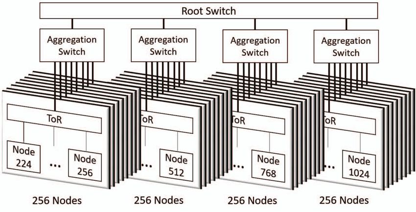
37one root switch, all interconnected by a 2 μs, 200 Gbit/s switching latency, or approximately 8 μs. A similar increase
network and arranged in a tree-topology, at a simulation rate is seen in the 50th percentile latency when moving from
of 3.42 MHz. This design represents a more realistic target crossing aggregation switches to crossing root switches. On
design point than the simpler design used as an example in the other hand, in both cases, there is no predictable change
Section III, since we make use of FireSim’s “supernode” in 95th percentile latency, since it is usually dominated by
feature to pack four simulated nodes per FPGA, giving a other variability that masks changes in number of hops for
total of 32 simulated nodes attached to each ToR switch. a request. Finally, we see that number of queries per second
Figure 10 shows this topology in detail. Each ToR switch decreases. This decrease is not as sharp as one would expect,
has 32 downlinks to nodes and one uplink to an aggregation because we limit the generated load to ≈10,000 requests
switch. Each aggregation switch has eight downlinks, each per server, since we are interested primarily in showing the
to one ToR switch and one uplink to the root switch. effects of latency rather than OS-effects or congestion.
Finally, the root switch has 4 downlinks to the 4 aggregation
VI. PAGE -FAULT ACCELERATOR
switches in the target topology. This topology is specified
to the FireSim simulation manager with around 10 lines In this section, as a case study to exemplify the cross-
of configuration code. More complicated topologies, such cutting architecture projects enabled by FireSim, we show
as a fat-tree, can similarly be described in the manager preliminary performance results for a “Page-Fault Accelera-
configuration, but we do not explore them in this work. tor” that removes software from the critical path of paging-
Compared to existing software simulators, this instantiation based remote memory.
of FireSim simulates an order of magnitude more nodes, There have been several recent proposals to disaggregate
with several orders of magnitude improved performance. memory in warehouse-scale computers, motivated by the
To map this simulation to EC2, we run 32 increasing performance of networks, and a proliferation of
f1.16xlarge instances, which host ToR switch novel memory technologies (e.g. HBM, NVM) [8], [10].
models and simulated server blades, and 5 m4.16xlarge In a system with memory disaggregation, each compute
instances to serve as aggregation and root-switch model node contains a modest amount of fast memory (e.g.
hosts. The cost of this simulation can be calculated for 2 high-bandwidth DRAM integrated on-package), while large
different EC2 pricing models: spot instances (bidding on capacity memory or NVM is made available across the
unused capacity) and on-demand (guaranteed instances). network through dedicated memory nodes.
To calculate the spot price of this simulation, we use the One common proposal to harness the fast local memory
longest stable prices in recent history, ignoring downward is to use it as a large cache for the remote bulk mem-
and upward spikes. This results in a total cost of ≈$100 ory. This cache could be implemented purely in hardware
per simulation hour. Using on-demand instances, which (e.g [33], [34]), which could minimize latency but may
have fixed instance prices, this simulation costs ≈$440 per involve complicated architectural changes and would lack
simulation hour. Using publicly listed retail prices of the OS insights into memory usage. An alternative is to manage
FPGAs on EC2 (≈$50K each), this simulation harnesses the cache purely in software with traditional paging mecha-
≈$12.8M worth of FPGAs. We expect that users will nisms (e.g. [3], [35]). This approach requires no additional
use cluster-scale experiments to prototype systems, with hardware, can use sophisticated algorithms, and has insight
datacenter-scale experiments to analyze behavior at-scale into memory usage patterns. However, our experiments show
once a system is already stable at cluster-scale. that even when paging to local memory, applications can be
As an example experiment that runs at this scale, we use slowed significantly due to the overhead of handling page
the mutilate memcached load generator (as in Section IV) faults, which can take several microseconds and pollute the
to generate load on memcached servers throughout the caches. In this case study, we propose a hybrid HW/SW
datacenter. In each experiment, there are 512 memcached cache using a new hardware device called the “page fault
servers and 512 mutilate load generator nodes, with each accelerator” (PFA).
load generator targeting one server. We run these in 3 The PFA works by handling the latency-critical page
different configurations: one where all requests remain intra- faults (cache-miss) in hardware, while allowing the OS
rack, one where all requests cross an aggregation switch (but to manage latency-insensitive (but algorithmically complex)
not the root switch), and one where all requests cross the evictions asynchronously. We achieve this decoupling with a
root switch, by changing which servers and load generators queue of free page frames (freeQ) to be used by the PFA for
are paired together. Table III shows average 50th percentile fetched pages, and a queue of new page descriptors (newQ)
latency, average 95th percentile latency, and total QPS han- that the OS can use to manage new page metadata. Execution
dled across all server-client pairs for these experiments. As then proceeds as follows:
expected, when we jump from crossing ToR switches only • The OS allocates several page frames and pushes their
to crossing aggregation switches for each request, the 50th addresses onto the freeQ. The OS experiences memory
percentile latency increases by 4 times the link latency, plus pressure and selects pages to evict to remote memory.
38and evaluation of a disaggregated memory system. In the
future, we plan to use FireSim to experiment with more
sophisticated configurations. For example, we will scale
the number of memory and application nodes to see how
contention for network and memory resources affects overall
performance. We are also investigating alternative remote
memory protocols such as Gen-Z [36].
VII. R ELATED W ORK
Computer architects have long used cycle-accurate sim-
ulation techniques to model machines and workloads, in-
cluding servers in warehouse-scale machines. Simulation
of machines at the scale of individual nodes was largely
Figure 11. Hardware-accelerated vs. software paging. sufficient for 2010-era datacenters; the commodity Ether-
net network used in most datacenters provided a natural
decoupling point to draw a boundary on the effects of
It marks them as “remote” in the page tables and then microarchitectural changes. Since most systems were built
provides them to the PFA for eviction. using commodity components, issues of scale could be
• The application attempts to access a remote page, measured in actual deployments and used to improve future
triggering the PFA to request the page from remote designs. For example, in cases where scale-out workloads
memory and place it in the next available free frame. differed from traditional workloads in terms of fine-grained
The application is then resumed. performance, performance-counter based mechanisms could
• Some time later (either through a background daemon, be used to analyze microarchitectural performance issues on
or through an interrupt due to full queues) the OS pops commodity servers at scale [37], [38].
all new page descriptors off the newQ and records the Other tools for simulating rack-scale systems can broadly
(now local) pages in its metadata. The OS typically be divided into three categories—software-based simulators
provides more free frames at this time. that provide flexibility but low performance, hardware-
We implemented the PFA in Rocket Chip and modified accelerated simulators that are expensive to deploy and
Linux to use it for all paging activity. For our baseline, we difficult to use, but provide high-performance, and statistical
modified Linux to use the memory blade directly through models that analyze the big-picture of datacenter perfor-
its normal paging mechanisms (similar to Infiniswap [35]). mance, but are not targeted towards modeling fine-grained
The memory blade itself is implemented as another Rocket system interactions. Below, we review this prior work.
core running a bare-metal memory server accessed through a
custom network protocol. Figure VI plots PFA performance A. Software Simulators
on two benchmarks: Genome, a de-novo genome assem- One approach to simulating warehouse-scale computers is
bly benchmark that involves random accesses into a large to take existing cycle-accurate full-system software simula-
hash table, and Qsort, a simple quicksort benchmark. Both tors and scale them up to support multiple nodes. One simu-
benchmarks were tuned to have a peak memory usage of lator that uses this approach is dist-gem5 [16], a distributed
64 MiB. Quicksort is known to have good cache behavior version of the popular architectural simulator gem5. This
and does not experience significant slowdowns when swap- simulator networks together instances of gem5 running on
ping. Genome assembly, however, has unpredictable access different nodes by moving synchronization messages and tar-
patterns, leading to significant cache thrashing in low local get packets. The primary advantage of these software-based
memory configurations. In both cases, the PFA significantly approaches is that they are extremely flexible. However,
reduces the overhead (by up to 1.4×). A more detailed this flexibility comes at the expense of performance—these
analysis shows that while the number of evicted pages is the software-based solutions are several orders of magnitude
same in both cases, using the PFA leads to a 2.5× reduction slower than FPGA-accelerated simulation platforms like
in metadata management time on average. While the same FireSim. Also, software models of processors are notoriously
code path is executed for each new page, the PFA batches difficult to validate and calibrate against a real design [39],
these events, leading to improved cache locality for the OS, and do not directly provide reliable power and area numbers.
and fewer cache-polluting page-faults for the application. By utilizing FPGAs in a cloud service, FireSim matches
Future implementations could use a background daemon many of the traditional flexibility advantages of software
for new-page processing, further decoupling the application simulators, excluding short build times. Software simulators
from new page management. have also traditionally had more sophisticated hardware
What we have presented here represents an initial design models than FPGA-based simulators, however the recent
39explosion in open-source hardware is providing realistic B. Hardware-accelerated Simulators
designs [40]–[42] that have the advantage of being truly Several proprietary tools exist for hardware-accelerated
cycle-exact and synthesizable to obtain realistic physical system simulation, such as Cadence Palladium, Mentor
measurements. Veloce, and Synopsys Zebu [48]. These systems are gener-
Another prior software-based approach is reflected in the ally prohibitively expensive (≈millions of dollars) and thus
Wisconsin Wind Tunnel (WWT) [43] project, which used unattainable for all but the largest industrial design groups.
the technique of direct execution to achieve high simulation Some existing projects use FPGAs to accelerate simu-
performance for individual nodes. In turn, WWT encoun- lation of computer systems, including large multicore sys-
tered similar performance bottlenecks as FireSim—network tems [49]. Most recently, projects in the RAMP collab-
simulation has a significant impact on overall simulation oration [50] pushed towards fast, productive FPGA-based
performance. Follow-on work in the WWT project [44] evaluation for multi-core systems [51]–[54]. However, most
explored the impact of several different network simula- of these simulation platforms do not support simulation of
tion models on the performance and accuracy of WWT. scale-out systems. To our knowledge, the closest simulator to
Similarly, we plan to explore more optimized network FireSim in this regard is DIABLO [17], [55]. Although DIA-
simulation models in FireSim in the future, which would BLO also uses FPGAs to simulate large scale-out systems,
trade-off accuracy vs. performance to support different user there are several significant differences between DIABLO
needs, using our current cycle-exact network model as the and FireSim:
baseline. FireSim already supports the other extreme of Automatically transformed RTL vs. Abstract Models.
the performance-accuracy curve—purely functional network In DIABLO, servers are modeled using handwritten Sys-
simulation—which allows individual simulated nodes to run temVerilog abstract RTL models of SPARC cores. Authoring
at 150+ MHz, while still supporting the transport of Ethernet abstract RTL models is far more difficult than developing
frames between simulated nodes. an actual design in RTL, and abstract RTL cannot be run
The Graphite simulator [45] takes a different software- through an ASIC flow to gain realistic power and area
based approach to simulating datacenters. Graphite can numbers. FireSim’s simulated servers are built by directly
simulate thousands of cores in a shared-memory system at applying FAME-1 transforms to the original RTL for a
high simulation rate (as low as 41× slowdown), but only server blade to yield a simulator that has the exact cycle-by-
by dropping cycle accuracy and relaxing synchronization cycle bit-by-bit behavior of the user-written RTL. Simulated
between simulated cores. Moreover, unlike full-system soft- switches in DIABLO are also abstract RTL models. In
ware simulators, Graphite only supports user applications FireSim, users still write abstract switch models, but since
and does not boot an OS. switches are not the simulation bottleneck, switch models
A final software-based approach to simulating datacenters can be written in C++ making them considerably easier to
is to abstractly model the datacenter as a set of statisti- modify. For detailed switch simulations, FireSim could be
cal events. This reduces simulation runtime, but sacrifices extended to also support FAME-1 transformations of real
the fidelity provided by detailed microarchitectural models. RTL switch designs.
This approach is used by datacenter-scale simulators like Specialized vs. Commodity Host Platform. DIABLO
BigHouse [46] and MDCSim [47]. BigHouse models a dat- uses a custom-built FPGA platform that cost ≈$100K at
acenter using a stochastic queuing simulation, representing time of publication, excluding operation and maintenance
datacenter workloads as a set of tasks with a distribution costs and the requirement for sysops expertise. This choice
of arrival and service times. The distribution is determined of platform makes it very difficult for other researchers to
empirically by instrumenting deployed datacenter systems. use DIABLO and reproduce results. In contrast, FireSim is
These distributions are then used to generate a synthetic deployed in a public cloud environment where Amazon has
event trace that is fed into a discrete-event simulation. The made all platform-specific FPGA scripts open-source [56].
simulation is distributed across multiple nodes by running a Similarly, the entire FireSim code base is open-source, which
separate instance of the simulator with a different random allows any user to easily deploy simulations on EC2 without
seed on each node, then collecting the individual results the high CapEx of a DIABLO-like system. Furthermore,
into a final merged result. MDCSim separates the simulation Amazon frequently gives substantial EC2 credit grants to
into three layers: user, kernel, and communication. It then academics for research purposes through their AWS Cloud
models specific services and systems in each layer, such as Credits for Research program [57].
web and database servers, schedulers, and NIC, as M/M/1
queues. While these simulation tools are useful for providing VIII. D ISCUSSION AND F UTURE W ORK
the “big picture” of datacenter performance and can do so As shown in Section IV, FireSim is sufficiently mature to
considerably faster than FireSim, FireSim instead focuses reproduce warehouse-scale workload performance phenom-
on modeling fine-grained interactions at the level of detailed ena. In this section, we outline some alternative use cases
microarchitecture changes between systems at-scale. and ongoing work to further build out and improve FireSim.
40You can also read