FLEXPOD METROCLUSTER IP WITH VXLAN MULTI-SITE FABRIC - LAST UPDATED: JULY 29, 2021 - CISCO
←
→
Page content transcription
If your browser does not render page correctly, please read the page content below
White Paper
                                                                                          Public

              FlexPod MetroCluster IP with
                VXLAN Multi-Site Fabric
                                                      Last Updated: July 29, 2021

© 2021 Cisco and/or its affiliates. All rights reserved.                             Page 1 of 88
Contents
Executive Summary ............................................................................................................................. 3
Solution Overview ............................................................................................................................... 4
Solution Architecture ........................................................................................................................... 5
Solution Design ................................................................................................................................. 23
Solution Validation............................................................................................................................. 70
Conclusion ........................................................................................................................................ 86
Appendix – References ..................................................................................................................... 87

© 2021 Cisco and/or its affiliates. All rights reserved.                                                                                  Page 2 of 88
Executive Summary
Cisco and NetApp have partnered to deliver FlexPod to support a broad range of enterprise workloads and
use cases. FlexPod solutions deliver systems and solutions that are designed, tested, and documented to
accelerate customer deployments while also reducing IT pain points and minimizing risks. FlexPod
datacenter solutions provide a foundational architecture for building private and hybrid cloud data centers
using Cisco and NetApp products and technologies. They incorporate design, technology, and product
best practices to ensure a successful deployment. The designs are robust, efficient, and scalable and
incorporate a range of technologies and products from Cisco and NetApp. FlexPod solutions also provide
design and deployment guidance through Cisco Validated Designs and white papers that Enterprises can
leverage during the different stages (planning, design, implementation, and production) of a roll-out.

This document describes the end-to-end design for a FlexPod data center solution, specifically the
FlexPod MetroCluster IP solution with a Cisco VXLAN Multi-Site fabric. The solution is a disaster-recovery
and business-continuity solution for the Virtualized Server Infrastructure (VSI) in an enterprise data center.
The solution uses an active-active data center design to ensure availability to at least one data center at all
times. The two active-active data centers can be in the same campus location or geographically dispersed
across different sites in a metropolitan area. The data center infrastructure is based on NetApp’s
MetroCluster IP solution using All-Flash FAS (AFF) arrays for storage, Cisco Unified Computing System™
(Cisco UCS®) for the compute, and VMware vSphere for the virtualization layer using one VMware vCenter
to manage the virtualized resources in both data centers. The network infrastructure in the solution is a
Cisco® VXLAN BGP Ethernet VPN (EVPN) Multi-Site fabric, managed by Cisco Data Center Network
Manager (DCNM) and built using Cisco Nexus 9000® series cloud-scale switches. The Cisco VXLAN fabric
provides Layer 2 extension and Layer 3 forwarding between the active-active data centers, enabling
applications to be deployed in either data center with seamless connectivity and mobility. The NetApp
MetroCluster IP solution uses synchronous replication between data centers to ensure continuous
availability to the storage data with zero data loss, zero recovery point objective (RPO), and near-zero
recovery time objective (RTO). A dedicated Layer 2 network is used in this design for the storage
replication traffic between sites to ensure the integrity of the replication data between data centers.

To simplify and accelerate the deployment of the end-to-end design, the solution uses a combination of
GUI-driven automation, RedHat Ansible automation and traditional methods for Day 0 through Day 2
activities. For example, Cisco DCNM’s Fabric Builder that provides a GUI-based automation for deploying a
VXLAN fabric, is used in this solution to deploy the VXLAN fabric in the two active-active data centers.
Similarly, the Day 2 network setup activities is automated using RedHat Ansible. RedHat Ansible is also
used for deploying the Cisco UCS compute and VMware virtualization in both data centers. For operational
simplicity, the Cisco UCS compute in the two data center locations are centrally managed from the cloud
using Cisco Intersight™. Cisco Intersight is a cloud-based Software-as-a-Service (SaaS) orchestration and
operations platform that uses a continuous integration/continuous development (CI/CD) model to deliver
new capabilities for both private and hybrid cloud deployments. Cisco Intersight now offers Intersight
Managed Mode (IMM), a new unified management architecture that uses standardized policies for all Cisco
UCS infrastructure regardless of their location. Customers can also manage this solution using Cisco IMM.

The VSI infrastructure in each data center is built using VMware vSphere 7.0U1, NetApp AFF A700 storage
with ONTAP 9.8, and Cisco UCS blade servers with Cisco UCS Manager (UCSM) release 4.1(3b). The
VXLAN Multi-Site fabric consists of Cisco Nexus® 9000 Series switches running NX-OS 9.3(6), managed
by Cisco DCNM 11.5(1). Also included in the solution are Cisco Intersight and NetApp Active IQ SaaS
platforms, NetApp ONTAP System Manager; NetApp Virtual Storage Console; NFS VAAI Plug-in, and
SnapCenter Plug-in for seamless VMware integration; and NetApp Active IQ Unified Manager.

© 2021 Cisco and/or its affiliates. All rights reserved.                                                   Page 3 of 88
Solution Overview
Introduction
The FlexPod solution is a predesigned, integrated, and validated architecture for the data center that
combines Cisco UCS servers, Cisco Nexus switches, and NetApp Storage Arrays into a single, flexible
architecture. FlexPod is designed for high availability, with no single points of failure, while maintaining
cost-effectiveness and flexibility in the design to support a wide variety of workloads.

In this FlexPod MetroCluster IP solution, the Cisco VXLAN Multi-Site solution allows you to interconnect
and centrally manage VXLAN fabrics deployed in separate, geographically dispersed data centers. NetApp
MetroCluster IP provides a synchronous replication solution between two NetApp storage clusters
providing storage high availability and disaster recovery in a campus or metropolitan area. The solution
enables you to design a VMware vSphere-based private cloud on a distributed integrated infrastructure
and deliver a unified solution that enables multiple sites to behave in much the same way as a single site
while protecting data services from a variety of single-point-of-failure scenarios, including a complete site
failure.

This document provides the end-to-end design of the FlexPod MetroCluster IP solution with Cisco VXLAN
Multi-Site fabric. The solution was validated by a walk-through of the buildout of the virtualized server
infrastructure in the two data centers directly connected to each other through the VXLAN fabric, with
additional supporting infrastructure for the solution. The FlexPod solution discussed in this document has
been validated for resiliency and fault tolerance during various failure scenarios as well as a simulated site
failure scenario.

Audience
The audience for this document includes, but is not limited to, sales engineers, field consultants,
professional services, IT managers, partner engineers, and customers who want to take advantage of an
infrastructure built to deliver IT efficiency and enable IT innovation.

What’s New?
The following design elements distinguish this version of FlexPod from previous FlexPod models:

     ●    Integration of Cisco VXLAN Multi-Site fabric in FlexPod Datacenter solutions to seamlessly support
          multiple sites
     ●    Integration of NetApp MetroCluster IP for synchronous data replication across the two data centers
     ●    Simplified operations and ease of automation by using Cisco DCNM for centralized management of
          a VXLAN Multi-Site fabric
     ●    Operational agility with Day 0 through Day 2 automation by using Cisco DCNM Fabric Builder for a
          GUI-driven, automated Day 0 buildout of the VXLAN fabric, and RedHat Ansible for Day 1+ network
          setup and Day 0-2 setup of the Cisco UCS and VMware virtual server infrastructure
     ●    Support for a VMware vSphere 7.0U1 stretched cluster across the FlexPod MetroCluster IP solution
          sites
     ●    Design, validation and operational aspects of this new FlexPod MetroCluster IP Datacenter design

© 2021 Cisco and/or its affiliates. All rights reserved.                                                       Page 4 of 88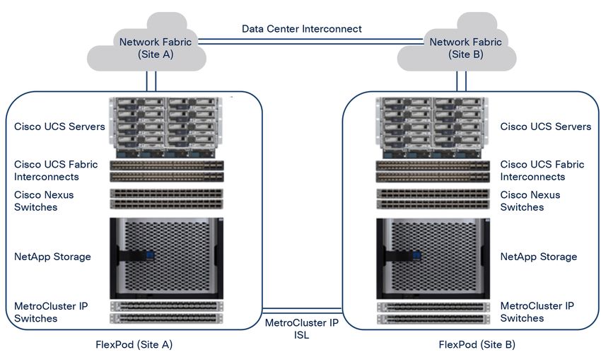
Solution Architecture
Introduction
At a high level, the FlexPod MetroCluster IP with VXLAN Multi-Site fabric solution consists of two FlexPods,
located at two sites separated by some distance, but connected and paired together to provide a highly
available, highly flexible, and highly reliable data center solution that can provide business continuity
despite a site failure. The FlexPod VSI at each site is connected to a larger data center fabric and the sites
are interconnected through an interconnect network. In addition, the two NetApp ONTAP clusters in a
MetroCluster IP configuration synchronously replicate data across sites through inter-site links (ISL) in a
MetroCluster IP network, as illustrated in Figure 1. Please note that the MetroCluster IP network can utilize
a dedicated network or it can be integrated into the larger data center fabric using the compliant switches
configuration, when the switches and network configuration meet the requirements. In the FlexPod
MetroCluster IP with VXLAN Multi-Site solution, a dedicated MetroCluster IP network is used.

Figure 1.
FlexPod MetroCluster IP Solution – High Level

The NetApp storage requirements for the MetroCluster IP network are:

     •     The supported maximum distance between sites is 700 km.

     •     The round-trip latency must be less than or equal to 7 ms.

     •     Packet loss and drops due to congestion or over-subscription must be less than or equal to 0.01%.

     •     The supported jitter value is 3 ms for a round trip (or 1.5 ms for one way).

For additional details and requirements for the NetApp MetroCluster IP solution deployment, please refer to
NetApp documentation on Install a MetroCluster IP configuration: ONTAP MetroCluster.

As stated earlier, the NetApp ONTAP storage clusters at both sites are paired together in a MetroCluster IP
configuration for synchronous data replication between sites using MetroCluster IP inter-switch links (ISL).

© 2021 Cisco and/or its affiliates. All rights reserved.                                                 Page 5 of 88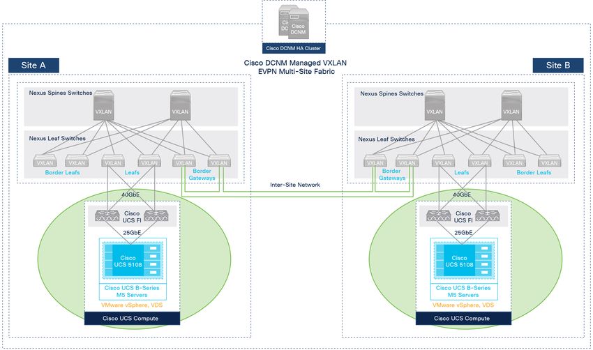
The MetroCluster IP solution helps ensure storage availability for continued business data services if a site
disaster occurs. The MetroCluster IP solution uses a high-performance Ethernet storage fabric between
sites. A dedicated four-node MetroCluster IP network is used in this solution and offers a simple solution
architecture that supports for up to 700 km distance between sites (refer to Figure 2).

Figure 2.
Four-Node MetroCluster IP Solution

A stretched VMware cluster implementation that combines the compute resources from both sites in a
high-availability configuration allows you to restart virtual machines in the surviving site if a site disaster
occurs. For normal operations, VM-Host affinity rules are followed so virtual machines are running locally at
a site using local site storage. If a disaster occurs, the virtual machines that are restarted at the surviving
site can continue to access their storage provided by the MetroCluster IP solution.

The FlexPod configuration at each site is connected to a data center network fabric at each site that
provides connectivity for the virtualized server infrastructure and for the applications hosted on that
infrastructure. A VXLAN Multi-Site data center fabric is used in this solution. However, different data center
network architecture options are available for connectivity within a site and for interconnecting the sites.
The solution requirements and architectures are discussed in upcoming sections.

Solution Requirements
The FlexPod MetroCluster IP with VXLAN Muti-Sie fabric solution is designed to address the following key
requirements:

     ●    Business continuity and disaster recovery in the event of a complete data center (site) failure
     ●    Flexible, distributed workload placement with workload mobility across data centers
     ●    Direct and independent access to external networks and services from each data center location
     ●    Site Affinity where virtual machine data is accessible locally, from the same data center site
     ●    Quick recovery with zero data loss if a failure occurs
     ●    Simplified administration and operation of the solution

From a design perspective, the high level design goals for the solution are:

     ●    Resilient design across all layers of the infrastructure with no single point of failure
     ●    Scalable design with the ability to independently scale compute, storage, and network bandwidth as
          needed

© 2021 Cisco and/or its affiliates. All rights reserved.                                                    Page 6 of 88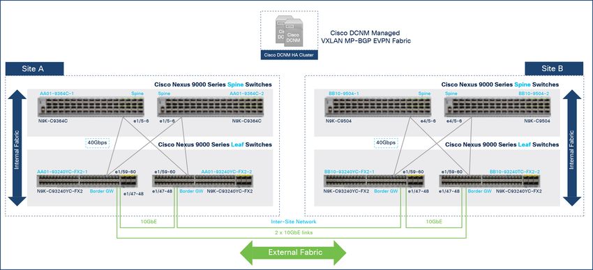
●    Modular design where you can change, upgrade, or replace components, resources, or sub-
          systems as needed

     ●    Flexible design across all layers of the solution that includes sub-system design, individual
          components used, and storage configuration and connectivity options
     ●    Ability to automate and simplify by enabling integration with external automation and orchestration
          tools
     ●    Incorporation of technology and product-specific best practices for all components used in the
          solution

The next section addresses different network architectures and design factors to consider when designing
a data center infrastructure solution for business continuity and disaster recovery.

Data Center Network
Traditional data center networks are built and managed in a de-centralized manner, on a device-by-device
basis. Rolling out a new application or service typically required network operators to access and configure
each device individually to achieve the desired connectivity. Enterprises that automated their network
operations still had to overcome significant challenges, not only in terms of time and resources but also
from automation and programmability options that were both limited and complex. Enterprises not only had
to manage a wide range of network protocols, technologies and design options, but they also had the
burden of managing automation capabilities that varied from vendor to vendor, product to product, and
sometimes even between products from the same vendor. As a result, Enterprises had significant upfront
work before any automation could be developed and used. Rolling out new applications or other changes
in the network could therefore take days, if not weeks, to complete and often impeded a business’s ability
to adapt and meet evolving business needs. To address these and other challenges, a number of
architectural shifts have occurred in the past few years as outlined below.

Modern data center networks typically use a Software-Defined Networking (SDN) architecture with
programmable infrastructure and centralized management entity or controller that manages the data center
network as a whole, as one fabric. In this architecture, the management plane is centralized and plays a
critical role in defining the behavior of the network’s control and data planes. When an application needs to
be deployed, the requirements are centrally defined on the controller and the controller then pushes the
corresponding network configuration and policies programmatically to the relevant nodes in the fabric to
achieve the desired results. This centralized approach minimizes user errors and helps ensure consistent
deployment across multiple nodes. It also minimizes configuration drift because it maintains the original
network intent on the controller which now serves as a single source of truth for the network fabric. In
many SDN solutions, the configuration on the individual nodes are continuously verified against the original
intent, and if a drift happens, you are alerted so you can resolve and synchronize the configuration. Some
architectures also prevent drifts altogether by allow configuration changes only through the controller. SDN
architectures, therefore, can bring agility and efficiency to enterprise networks by enabling you to deploy
network changes quicker, uniformly and in a more consistent manner, with fewer errors regardless of the
scale of the fabric.

SDN architectures also make it easier for enterprises to automate their network infrastructure because
operators no longer have to interface with each network device individually. They can programmatically
convey the network intent to the controller and the controller will then take care of implementing that intent
on the individual nodes in the fabric. Automating the network fabric and the data center infrastructure is a
primary goal for enterprises considering a DevOps operational model which requires access to all

© 2021 Cisco and/or its affiliates. All rights reserved.                                                   Page 7 of 88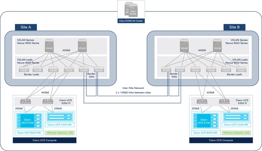
infrastructure as code (IaC). It is also critical for enterprises looking to achieve cloud-like agility in their
private cloud and hybrid cloud deployments or to simply speed up IT operations.

Another architectural shift in modern data centers is in the network topology itself. Enterprises are
migrating from traditional two- and three-tier hierarchical designs with flat two-tier Clos-based spine-and-
leaf designs that are better suited for the traffic patterns seen in data center networks, where the levels of
East-West traffic are significantly higher than in other parts of the enterprise. Clos-based fabrics simplifies
the network topology and provides consistent and predictable routing with 3-stage forwarding with
predictable performance and horizontal scaling. To realize these benefits, Clos topologies impose specific
role-based characteristics on the nodes in the fabric. For example, endpoints connect only to switches in a
leaf role and never to spine switches, spine switches connect to all leaf switches in the fabric but never
connect directly to each other, leaf switches connect to all spine switches but not to each other for fabric
connectivity, all of which brings uniformity, predictability, and most importantly, consistent performance
across the network fabric (refer to Figure 3).

Figure 3.
Data Center Network - Traditional Three-tier Hierarchical vs. Two-tier Clos Design

The Clos-based design is also the foundation for another architectural shift in modern data center fabrics,
namely Virtual Extensible LAN (VXLAN) overlay networks. VXLAN overlay networks enable Layer 2
extension and Layer 3 forwarding across a routed IP network (underlay) by establishing tunnels between
leaf switches, referred to as VXLAN Tunnel Endpoints (VTEPs). VXLAN networks also provide other benefits
such as :

     ●    Scalability: VLAN networks have a 4096-segment limit. VXLAN networks can scale up to 16 million
          segments.
     ●    Flexibility: Workload placement is not limited by the physical location of compute resources in the
          network. VXLAN networks allow you to place workloads anywhere in the network fabric, regardless
          of where the compute resources physically connect to the network fabric. In a data center IP
          network, this requires layer 2 extension and VXLAN provides it by establishing VXLAN tunnels
          between top-of-rack switches that the compute resources connect to. The workloads are uniquely
          identified in a shared data center IP network using a VXLAN segment ID or Virtual Network Identifier
          (VNID). Traffic using the same VNID are in the same network segment regardless of where it
          physically originated in the network.
     ●    Mobility: Virtual machines and workloads in a given network segment will use the same VNID
          regardless of where they connect to in the network fabric. This provides the necessary layer 2

© 2021 Cisco and/or its affiliates. All rights reserved.                                                           Page 8 of 88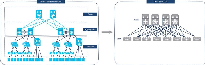
extension, enabling workloads to be moved anywhere that the data center fabric connects.

For FlexPod customers, all of the above architectural shifts in data center networks means more options
and better solutions. FlexPod supports both the traditional 2- and 3-tier hierarchical designs as well as the
modern SDN-based designs. The two SDN solutions supported in FlexPod are:

     ●    Cisco Application Centric Infrastructure (Cisco ACI®) fabric - with support for Multi-Pod or Multi-
          Site connectivity

     ●    Cisco DCNM-managed VXLAN MP-BGP EVPN fabric - with support for VXLAN Multi-Site
          connectivity

Both SDN solutions use a 2-tier Clos-based spine-and-leaf topology. FlexPod can also be deployed using
traditional 2- or 3-tier hierarchical design. When a SDN fabric is used, the Cisco UCS compute and NetApp
storage in the solution will connect to leaf switches in the fabric, (Cisco ACI or Cisco VXLAN MP-BGP
EVPN), or to top-of-rack switches in a traditional 2- or 3-tier design. The data center network fabric for the
FlexPod MetroCluster IP solution in this document is a VXLAN MP-BGP EVPN Multi-Site fabric, managed
using Cisco DCNM, which serves as the centralized controller for the fabric. The solution also includes a
separate Layer 2 network for synchronous replication traffic between NetApp MetroCluster IP storage
systems in the active-active data centers.

All three network architectures are discussed in greater detail in upcoming sections of this document. All
three architectures enable enterprises to build active-active data centers that provide business continuity
and disaster recovery(BC/DR). The active-active data centers can be in a single location such as a campus
environment or distributed across different geographical sites. The primary focus of each architecture is to
interconnect data centers and provide seamless connectivity and mobility across data centers. The
architecture must also deliver an end-to-end network design that includes a design for the network within
a data center as well as a design for interconnecting them.

Before we look at the network architectures, it is important to first have a good understanding of the
connectivity and flow of traffic in an enterprise data center, as outlined in the next section.

Connectivity
A data center network fabric provides the Layer-2 and Layer-3 connectivity necessary for bringing the
compute and storage infrastructure online. When the infrastructure is operational, the network fabric
provides Layer-2 and Layer-3 connectivity for deploying and hosting the workloads (applications, services,
etc.) on that infrastructure. In a BC/DR infrastructure solution using active-active data centers, the
workloads can be active in either data center, and you can move workloads between data centers as
needed. The application workloads distributed across data centers should also be able to communicate
across data centers, across application tiers, and between components in the same tier. This
communication of data centers and workload mobility is a critical requirement to ensure business continuity
in if a disaster occurs.

Traffic Flow
The traffic traversing a data center network fabric can be broadly categorized as being either infrastructure
or application traffic. The infrastructure traffic is any traffic required to build, operate, and maintain the data
center infrastructure. Application traffic is any traffic generated by workloads hosted on that infrastructure,
when it is operational. However, note that traffic to/from infrastructure management elements hosted on
the infrastructure are also categorized as infrastructure traffic since it used to operate the infrastructure,
even if it is hosted on the infrastructure as application workloads are. The important distinction is that the

© 2021 Cisco and/or its affiliates. All rights reserved.                                                       Page 9 of 88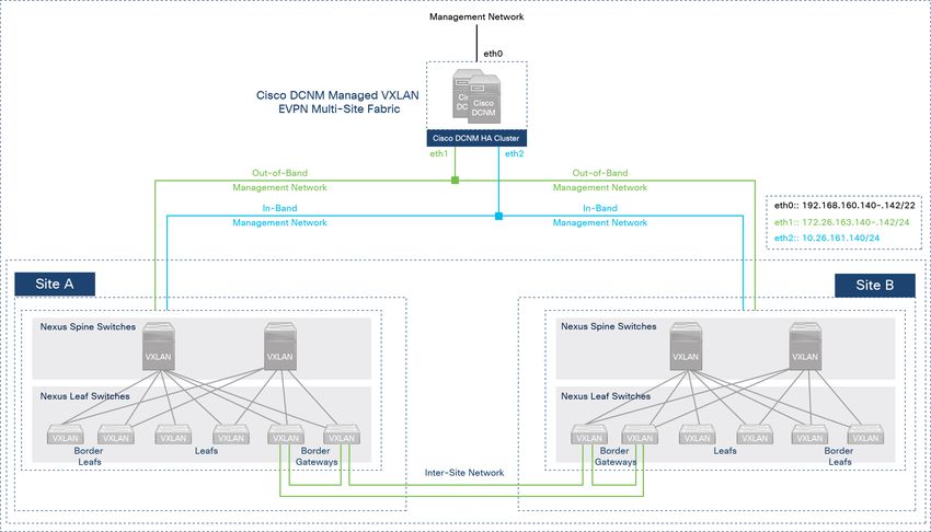
infrastructure traffic and connectivity are considered to be foundational and a pre-requisite for hosting
workloads, and also for providing capabilities such as flexible workload placement, mobility and high
availability.
All data center traffic can also be characterized as:
● East-West, for traffic between endpoints connected to the same data center fabric
● North-South, for traffic to/from enterprise users in campus, WAN, or remote locations accessing
applications and services hosted in the data centers or for accessing cloud services on the Internet;
it could also be for connecting to management elements that manage the infrastructure within the
data center
For the FlexPod BC/DR solution in this document,
● East-West traffic also includes any traffic between endpoints attached to different data centers in
the active-active design; for example, the storage replication traffic between NetApp storage within
and across data centers.
● North-South traffic is the same as before but it includes traffic to/from applications and services
hosted in either of the data centers in the active-active design. The traffic patterns for these flows
can also vary, depending on the network design. The design could use a common access point for
outside/external connectivity; for example, each site could use the inter-site network to also
connect to outside/external networks. Alternatively, each location could use a dedicated and
independent connection for connecting to outside/external networks. For this solution, regardless of
the external connectivity design, it is important to ensure that the design meets the BC/DR
requirements for availability.
Network Architecture Options
The following sections provide different network architectures available for a BC/DR solution using an
active-active design that provides Layer-2 and Layer-3 forwarding of traffic within a data center (East-
West) and traffic from outside networks to the data center and conversely (North-South). For the FlexPod
MetroCluster IP solution in this document, this paper discusses additional design options for forwarding
synchronous storage replication traffic within and across data centers.
Option 1: VXLAN BGP EVPN Multi-Site Fabric
The Cisco VXLAN BGP EVPN Multi-Site fabric provides a highly flexible, scalable, and resilient network
architecture for enabling business continuity and disaster recovery in modern data centers. This
architecture brings Cisco’s industry-leading, standards-based, innovative suite of products and
technologies to deliver a programmable infrastructure with orchestration and management capabilities for
meeting the needs of modern data centers.
The VXLAN BGP EVPN Multi-Site architecture uses VXLAN overlays and a 2-tier Clos-based IP underlay
network, built using Nexus® 9000 Series-based spine-and-leaf switches. VXLAN overlays enable you to
build Layer 2 and Layer 3 networks and extended them across data center locations, enabling multiple data
centers to be interconnected with seamless forwarding of East-West traffic between them. Though the
flexibility and simplicity of building VXLAN overlays across any IP underlay is extremely useful, the resulting
overlay network is a flat network that spans data centers with no fault isolation neither in the control plane
nor in the data plane. With Layer 2 extension, the overlays can result in large multi-data center bridge
domains even when the underlay network is a well-designed, Clos-based IP fabric with hierarchical
addressing, fault isolation, etc. To address this problem, Cisco, along with other industry partners have
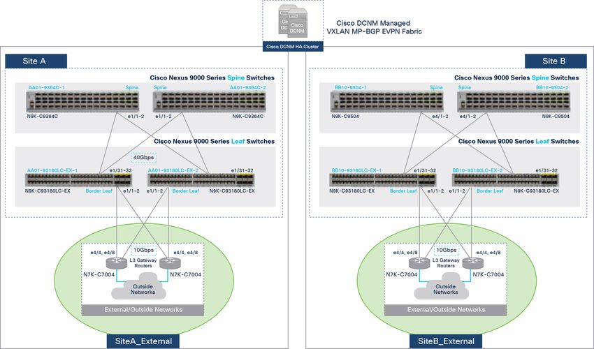
© 2021 Cisco and/or its affiliates. All rights reserved. Page 10 of 88developed the VXLAN BGP EVPN Multi-Site architecture to interconnect data centers. In the VXLAN multi- site architecture, the end-to-end VXLAN overlay network is split into failure domains where the data centers and the interconnect between data centers are all in different failure domains. The overlay segmentation provides not only fault isolation and segmentation, but also routing hierarchy without sacrificing seamless connectivity or mobility between data centers. The transition between overlay segments also provides a point of control for enforcing forwarding and security policies between data centers. This approach is also more scalable, enabling enterprises to interconnect multiple data centers as needed. Figure 4 illustrates this architecture. Figure 4. VXLAN EVPN Multi-Site Architecture FlexPod customers can take advantage of the VXLAN BGP EVPN architecture to build individual data center fabrics and extend them to multiple locations using the Multi-Site architecture. The FlexPod MetroCluster IP solution in this document uses this approach to build active-active data centers as shown in Figure 5. © 2021 Cisco and/or its affiliates. All rights reserved. Page 11 of 88
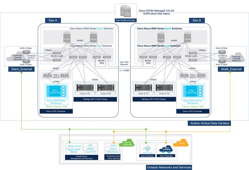
Figure 5.
Active-Active Data Centers Using VXLAN EVPN Multi-Site Architecture

In this solution, the VXLAN EVPN Multi-Site architecture is used to provide BC/DR by interconnecting data
center fabrics in two sites. Other network architectures options for enabling active/active data centers are
discussed in the next two sections.

The Cisco VXLAN BGP EVPN Multi-Site fabric is managed by Cisco DCNM deployed outside the fabric.
Cisco DCNM is deployed as a cluster of multiple nodes for high availability. The network fabric consisting
of spines and leaf switches is built using Nexus 9000 series switches capable of supporting VXLAN
overlays. The fabric provides seamless Layer 2 extension and Layer 3 forwarding for both infrastructure
and application and services VMs hosted on the infrastructure.

For VXLAN fabrics, Cisco DCNM serves as an SDN controller to provision and operate the fabric. Cisco
DCNM will need to first discover and add switches to a fabric. Cisco DCNM will assume a default role
(spine, leaf) for the switch based on the model, but you can easily change the role (for example, from spine
to leaf or leaf to border or border gateway, etc.). Cisco DCNM can also bootstrap or Pre-boot Execution
Environment (PXE) boot individual switches. Cisco DCNM Fabric Builder then uses the discovered switches
to deploy a complete VXLAN fabric. Fabric Builder provides a GUI-based mechanism for automating the
deployment of a VXLAN fabric. Additional connectivity such as connectivity to outside/external networks
(including managing the configuration on external gateways), and inter-site connectivity between data
centers can also be deployed from Cisco DCNM. The following screenshot shows the Fabric Builder GUI,
where the tabs represent different configuration categories.

© 2021 Cisco and/or its affiliates. All rights reserved.                                               Page 12 of 88
The administrator can save the provided inputs and initiate an automated deployment of the VXLAN fabric
with one click of a button. All the necessary configuration to bring up a fabric are deployed across all
nodes in the fabric. The screenshot below shows the VXLAN fabric deployed in Site-A for this solution,
using Fabric Builder. To bring up a switch in a VXLAN fabric typically requires 200 to 300 lines of
configuration, if not more. Using DCNM Fabric Builder, therefore, significantly accelerates the deployment
and ensures that it is deployed correctly, consistently and without user errors.

Cisco DCNM as an SDN controller for the fabric also makes it easier to automate the network fabric for
northbound integration into a DevOps tool chain or other enterprise tools because you can develop
automation for Cisco DCNM to manage the whole fabric rather than automating on a per-switch basis.

© 2021 Cisco and/or its affiliates. All rights reserved.                                              Page 13 of 88
Cisco DCNM also continuously verifies the original intent against the configuration on the nodes to prevent
configuration drifts and other problems. Cisco DCNM can also monitor and provide lifecycle management
of the fabric after deployment. Cisco DCNM simplifies Day 2 operations by providing easy-to-use
workflows follows for upgrades, Return Material Authorization (RMAs) in addition to network-wide visibility,
fault monitoring, and automated consistency checks at regular intervals to prevent configuration drifts.
Cisco uses pre-defined template policies for the automated deployment and configuration of all devices
that Cisco DCNM manages and deploys, but administrators can also use free-form templates to customize
as needed. Cisco DCNM also integrates with other Cisco orchestration and operational tools such as
Network Insights and Multi-Site Orchestrator to provide centralized policy-based management of larger
fabrics and for more in-depth monitoring of all fabrics.

Option 2: Cisco ACI Multi-Pod Fabric
The Cisco ACI fabric is an application-centric, policy based, secure SDN architecture for the data center.
To enable active-active data centers for BC/AR, you can extend the network fabric to multiple data centers
using the Cisco ACI Multi-Pod architecture. The Cisco ACI architecture also uses a 2-tier Clos topology,
built using Nexus 9000 series-based spine-and-leaf switches and VXLAN overlays for forwarding East-
West traffic within and across data centers. However, unlike the other two architectures presented in this
document, Cisco ACI builds the network fabric with minimal input from the network administrator or
operator. The fabric is pre-designed based on Cisco’s years of networking expertise, and deployed using
design, product, and technology best practices. Cisco ACI hides the complexities of designing and
deploying the IP underlay and the VXLAN overlay, and instead focusses on enabling a data center fabric
ready for deploying applications. The architecture assumes that the primary goal of a data center fabric is
for supporting applications and therefore, Cisco ACI focusses on accelerating, simplifying, and optimizing
application roll outs and on the networking and policies associated with that roll out, rather than on how the
network is built.

Cisco ACI also uses an intent-based framework to deliver agility. It captures high-level intent (application,
business) in the form of a policy and translates the policy into network constructs to provision the
networking, security, and other services on the individual switches that make up the fabric. The Cisco
Application Policy Infrastructure Controller (Cisco APIC) serves as a centralized controller for the fabric and
manages it as one system, with tight integration between hardware and software, physical and virtual
elements, and innovative Cisco Application-Specific Integrated Circuits (ASICs) that bring exceptional
capabilities to modern data centers. Cisco APIC is a critical architectural component of the Cisco ACI
solution. It is typically deployed as a high-availability cluster (3 nodes minimum) with the ability to
horizontally scale as needed by adding more nodes. It is the unified point of automation and management
for the Cisco ACI fabric, policy enforcement, and health monitoring.

Cisco ACI architecture is very extensible, and it provides several architectural options to meet different
enterprise requirements. They include Cisco ACI Multi-Pod for interconnecting data center fabrics
managed by the same Cisco APIC cluster, Cisco ACI Remote Leaf for edge/satellite deployments, Cisco
ACI Mini Fabric, Cisco ACI Multi-Site with Multi-Site Orchestrator for interconnecting multiple data center
sites, and Cisco Cloud ACI with Cloud APIC and Cisco Cloud Services Router 1000V (Cisco CSR 1000V)
for public cloud deployments (Amazon AWS, Microsoft Azure). The Cisco ACI architecture can orchestrate
seamless connectivity across these environments using a common policy model. The common policy and
operating model significantly reduces the cost and complexity of managing multi-data center and multi-
cloud data center deployments.

FlexPod customers can leverage the Cisco ACI architecture for the data center fabric, and then expand and
extend the fabric using one of the above architectural options. For an active-active data center design such

© 2021 Cisco and/or its affiliates. All rights reserved.                                                  Page 14 of 88
as the one in this solution, you can use both Cisco ACI Multi-Pod and Cisco ACI Multi-Site design to build
and interconnect data center fabrics. However, there are some important factors that you should consider
when deciding which one to use.

The Cisco ACI Multi-Site architecture is designed to interconnect ACI fabrics in different geographical sites
or regions and to enable a large scale-out architecture for the network fabric. Each fabric is referred to as
a “Site” in the Cisco ACI Multi-Site architecture, with each site managed by a separate APIC cluster. Each
fabric is also part of a larger Cisco ACI Multi-Site fabric that helps to ensure connectivity between sites
using a common policy model that extends end to end, across all data center sites. A critical element of
this architecture is the Cisco Multi-Site Orchestrator (Cisco MSO). Cisco MSO provides a single point of
administration for all inter-site policies which is then extended to the different APIC clusters managing the
different ACI fabrics. Cisco MSO also automates and manages the interconnect between ACI fabrics to
enable multi-tenant Layer 2 and Layer 3 connectivity between sites. Multiprotocol BGP (MP-BGP) EVPN
sessions are established to exchange endpoint reachability information, and VXLAN tunnels are established
for forwarding Layer 2 and Layer 3 traffic across sites. Cisco MSO is also a common point of automation
that can be very helpful in automating large ACI deployments.

The Cisco ACI Multi-Pod is designed to interconnect ACI networks in different physical data center
locations but within the same campus or metropolitan area. The ACI networks are managed as one fabric,
using a single APIC cluster. The ACI network in each data center is referred to as a “Pod” in the Cisco ACI
Multi-Pod architecture. Each Pod can be considered a separate availability zone where each Pod is a
separate network fault domain because each Pod runs separate instances of control plane protocols,
though all are part of the same ACI fabric and are managed by the same APIC cluster. Cisco ACI Multi-Pod
is administratively and operationally simpler by managing multiple data center networks as a single, logical
fabric. Policy changes are seamlessly deployed across all Pods because they are part of the same ACI
fabric and they are managed by the same APIC. Pods are, therefore, part of the same tenant change
domain, where any changes for a given tenant are immediately applied to all Pods.

Cisco ACI Multi-Pod is commonly used in active-active data center deployments that also have some or all
of the following requirements :

     ●    Both data centers are part of the same Virtual Machine Manager (VMM) domain.
     ●    VMware Distributed Resource Scheduler (DRS) initiates workload mobility between data centers.
     ●    vSphere High Availability or Fault Tolerance is configured across data centers.
     ●    The data centers have application clustering that requires Layer 2 extension with broadcast, unicast,
          and multicast between data centers.
     ●    Clustered network services are (firewalls, load balancers) across data centers.

Based on the requirements for this solution, Cisco ACI Multi-Pod architecture is a better fit than Cisco ACI
Multi-Site for building active-active data centers for business continuity and disaster recovery. For more
details, refer to the Design Guide and Deployment Guide of the validated FlexPod MetroCluster IP solution
with Cisco ACI Multi-Pod.

Option 3: Hierarchical Layer 2/Layer 3
You also can build data center networks using hierarchical Layer 2/Layer 3 (IP) designs with a network of
Layer 2 or Layer 3 switches at each tier. The network design typically involves an access layer (same as
other network architectures), but also an aggregation layer and core layers. Traditionally, these aggregation
layers are Layer 3, with the core being Layer 2 or Layer 3. Figure 6 shows a hierarchical 3-tier architecture.

© 2021 Cisco and/or its affiliates. All rights reserved.                                                  Page 15 of 88
You also can use enterprise data center networks with this type of architecture or a variation of this model
(for example, collapsed core/aggregation) in a FlexPod MetroCluster IP solution for BC/DR.
Figure 6.
Hierarchical 3-Tier Architecture
The connectivity between the data centers would require a Data Center Interconnect (DCI) technology such
as Overlay Transport Visualization (OTV) over dark fiber, Dense Wavelength Division Multiplexing (DWDM)
or IP transport. Alternatively, you also could use Multiprotocol Label Switching (MPLS)-based EVPNs or
other Layer 2 and Layer 3 interconnect technologies.
Extended Layer 2 Design
For a small solution deployment that might be cost-sensitive, simply extending Layer 2 across sites will
require the least amount of hardware to implement a FlexPod MetroCluster IP solution. For site-to-site
connectivity that uses extended Layer 2 connectivity natively, you can achieve additional cost optimizations
by sharing the Inter-Switch Link (ISL) between sites for MetroCluster IP and non-MetroCluster IP usage if
you have sufficient bandwidth. In addition, you can use the Cisco Nexus switches in a FlexPod as compliant
MetroCluster IP switches if they meet the requirements of the compliant switches, thus eliminating the
need for additional dedicated MetroCluster IP switches.
Following are the general requirements for a MetroCluster IP solution with compliant switches:
• Only platforms that support MetroCluster IP and provide dedicated ports for switchless cluster
interconnects are supported, including NetApp AFF A300, AFF A320, AFF A400, AFF A700, AFF A800,
FAS8200, FAS8300, FAS8700, FAS9000, ASA AFF A400, ASA AFF A700, and ASA AFF A800.
• You can connect the MetroCluster IP interface to any switch port that you can configure to meet the
requirements.
© 2021 Cisco and/or its affiliates. All rights reserved. Page 16 of 88• The speed of the switch ports required depends on the platform. For example, it is 25 Gbps for AFF
A300, 40 Gbps for AFF A700, and 40/100 Gbps for AFF A800.
• The ISLs must be 10 Gbps or higher and must be sized appropriately for the load on the MetroCluster
configuration.
• The MetroCluster IP configuration must be connected to two networks, and each MetroCluster IP node
must be connected to two network switches.
• The network must meet additional requirements for ISL sharing, cabling, and required settings on
intermediate switches.
• The maximum transmission unit (MTU) of 9216 must be configured on all switches that carry
MetroCluster IP traffic.
• The compliant switches must support Quality of Service (QoS)/traffic classification, explicit congestion
notification (ECN), Layer 4 port-VLAN load-balancing policies to preserve order along the path, and
Layer 2 Flow Control (L2FC).
• The cables connecting the nodes to the switches must be purchased from NetApp and supported by
the switch vendor.
Figure 7 shows two identical FlexPod configurations, one at each site, that are connected by the ISLs. You
can separate the NetApp ONTAP MetroCluster IP sites by up to 700 km. There are two types of
connections between the Nexus switches and the NetApp storage controllers; they are used for client data
traffic and MetroCluster IP data replication between the two ONTAP clusters. The ONTAP Mediator
monitoring the solution from a third site enables the solution to perform an automated, unplanned
switchover when one of the sites experiences a failure.
Figure 7.
FlexPod MetroCluster IP Solution Architecture with ISL Sharing and Compliant FlexPod Switches
For details about the requirements of using shared Layer 2 ISL connectivity for both MetroCluster IP and
non-MetroCluster IP traffic between sites, deploying a MetroCluster IP solution with compliant switches,
and using the ONTAP storage controllers that support MetroCluster IP deployment with compliant switches,
please refer to NetApp documentation on Install a MetroCluster IP configuration: ONTAP MetroCluster and
information on NetApp Hardware Universe.
© 2021 Cisco and/or its affiliates. All rights reserved. Page 17 of 88Compute
The Cisco UCS compute infrastructure in FlexPod solutions is a revolutionary architecture for deploying and
managing servers in the data center. The Cisco UCS infrastructure can now be deployed and managed
from Cisco Intersight in IMM mode or be managed using Cisco UCS Manager. Following are some unique
differentiators of Cisco UCS servers managed using Cisco UCS Manager running on Cisco UCS Fabric
Interconnects. The benefits of using Cisco Intersight are discussed in the next section.
Cisco UCS Manager
● Embedded management: When the Cisco UCS servers are managed using the embedded firmware
in the Fabric Interconnects, it eliminates the need for any external physical or virtual devices to
manage the servers.
● Unified fabric: Cisco UCS servers in a blade-server chassis or rack servers connect to the Cisco
UCS 6000 Series Fabric Interconnects, a single Ethernet cable is used for LAN, storage-area
network (SAN), and management traffic. This converged I/O results in reduced cables, Small Form-
Factor Pluggables (SFPs), and adapters, thereby reducing capital and operational expenses of the
overall solution.
● Auto-discovery: By simply inserting the blade server in to a chassis or by connecting the rack server
to a fabric interconnect, the compute resources are discovered and added to the inventory
automatically without any management intervention. The combination of unified fabric and auto-
discovery enables the wire-once architecture that Cisco UCS provides. Therefore, Cisco UCS
architecture enables the compute capacity to be easily extended by using the existing external
connectivity to LAN, SAN, and management networks.
● Policy-Based Resource Classification: When Cisco UCS Manager discovers a compute resource, , it
can automatically classify it to a given resource pool based on defined policies. The policy-based
resource classification capability is particularly useful in multi-tenant cloud deployments.
● Combined rack and blade server management: Cisco UCS Manager can manage Cisco UCS B-
Series blade servers and Cisco UCS C-Series rack servers under the same Cisco UCS domain. This
feature, along with stateless computing, makes compute resources truly hardware form-factor—
agnostic.
● Model-based management architecture: The Cisco UCS Manager architecture and management
database is model-based and data-driven. An open Extensible Markup Language (XML) application
programming interface (API) is provided to operate on the management model. This API enables
easy and scalable integration of Cisco UCS Manager with other management systems.
● Policies, pools, and templates: The management approach in Cisco UCS Manager is based on
defining policies, pools, and templates, instead of cluttered configuration, enabling a simple, loosely
coupled, data-driven approach in managing compute, network, and storage resources.
● Loose referential integrity: In Cisco UCS Manager, a service profile, port profile, or policies can refer
to other policies or logical resources with loose referential integrity. A referred policy cannot exist at
the time of authoring the referring policy or a referred policy can be deleted even though other
policies are referring to it. With this feature different subject matter experts can work independently
from each-other, providing great flexibility where different experts from different domains, such as
network, storage, security, server, and virtualization, work together to accomplish a complex task.
● Policy resolution: In Cisco UCS Manager, you can create a tree structure of organizational unit
hierarchy that mimics the real-life tenants and/or organization relationships. You can define various
© 2021 Cisco and/or its affiliates. All rights reserved. Page 18 of 88policies, pools, and templates at different levels of organization hierarchy. A policy referring to
another policy by name is resolved in the organizational hierarchy with the closest policy match. If
no policy with a specific name is found in the hierarchy of the root organization, then the special
policy named “default” is searched. This policy-resolution practice enables automation-friendly
management APIs and provides great flexibility to owners of different organizations.
● Service profiles and stateless computing: A service profile is a logical representation of a server,
carrying its various identities and policies. You can assign this logical server to any physical
compute resource as far as it meets the resource requirements. Stateless computing enables
procurement of a server within minutes; this task used to take days in older server management
systems.
● Built-in multi-tenancy support: The combination of policies, pools, and templates; loose referential
integrity; policy resolution in the organizational hierarchy; and a service profiles-based approach to
compute resources makes Cisco UCS Manager inherently friendly to multi-tenant environments
typically observed in private and public clouds.
● Extended memory: The enterprise-class Cisco UCS B200 M5 Blade Server extends the capabilities
of the Cisco UCS portfolio in a half-width blade form factor. The Cisco UCS B200 M5 harnesses the
power of the latest Intel Xeon Scalable series processor family CPUs with up to 3 TB of RAM (using
128-GB dual inline memory modules [DIMMs]): These modules allow the required ratio of huge
virtual machines to physical servers in many deployments or allow large memory operations
required by certain architectures such as big data.
● Simplified QoS: Even though Fibre Channel and Ethernet are converged in the Cisco UCS fabric,
built-in support for QoS and lossless Ethernet makes it seamless. Network QoS is simplified in Cisco
UCS Manager by representing all system classes in one GUI panel.
Cisco Intersight Platform
The Cisco Intersight platform is a SaaS based orchestration and operations platform that provides global
management of Cisco UCS infrastructure located anywhere. The Cisco Intersight platform provides a
holistic approach to managing distributed computing environments from the core to the edge. Its virtual
appliance (available in the Essentials edition) offers you deployment options while still offering all the
benefits of SaaS. This deployment flexibility can enable you to achieve a higher level of automation,
simplicity, and operational efficiency.
Cisco UCS systems are fully programmable infrastructures. The Cisco Intersight platform provides a
RESTful API to provide full programmability and deep integrations with third-party tools and systems. The
platform and the connected systems are DevOps-enabled to facilitate continuous delivery. Customers have
come to appreciate the many benefits of SaaS infrastructure-management solutions. Cisco Intersight
monitors the health and relationships of all the physical and virtual infrastructure components. Telemetry
and configuration information is collected and stored in accordance with Cisco’s information security
requirements. The data is isolated and displayed through an intuitive user interface. The virtual appliance
feature enables you to specify what data is sent back to Cisco with a single point of egress from the
customer network.
The cloud-powered intelligence of Cisco Intersight can assist organizations of all sizes. Because the Cisco
Intersight software gathers data from the connected systems, it learns from hundreds of thousands of
devices in diverse customer environments. It combines this data with Cisco best practices to enable Cisco
Intersight to evolve and become smarter. As the Cisco Intersight knowledge base increases, it reveals
trends, and provides information and insights through the recommendation engine.
© 2021 Cisco and/or its affiliates. All rights reserved. Page 19 of 88In addition to Cisco UCS server status and inventory, Cisco Intersight provides the Cisco UCS server
Hardware Compatibility List (HCL) check for Cisco UCS server drivers. In this FlexPod validation, you can
use the HCL check to verify that the correct Cisco UCS Virtual Interface Card (VIC) nfnic and nenic drivers
are installed.
Cisco UCS B200 M5 Blade Servers
The Cisco UCS B200 M5 Blade Server (Figure 8) used in this FlexPod solution is a half-width blade.
Figure 8.
Cisco UCS B200 M5 Blade Server
It features:
● 2nd Gen Intel Xeon Scalable and Intel Xeon Scalable processors with up to 28 cores per socket
● Up to 24 Dial-on-Demand Routing 4 (DDR4) DIMMs for improved performance with up to 12 DIMM
slots ready for Intel Optane DC Persistent Memory
● Up to two GPUs
● Two Small-Form-Factor (SFF) drive slots
◦ Up to 2 Secure Digital (SD) cards or M.2 Serial Advanced Technology Attachment (SATA) drives
◦ Up to 80 Gbps of I/O throughput with the Cisco UCS 6454 Fabric Interconnects
For more information about the Cisco UCS B200 M5 Blade Servers, please visit:
https://www.cisco.com/c/en/us/products/collateral/servers-unified-computing/ucs-b-series-blade-
servers/datasheet-c78-739296.html.
Cisco UCS C220 M5 Rack Servers
The Cisco UCS C220 M5 Rack Server shown in Figure 9 is a high-density 2-socket rack server that can
also be used to provide compute resources in this FlexPod solution.
Figure 9.
Cisco UCS C220 M5 Rack Server
© 2021 Cisco and/or its affiliates. All rights reserved. Page 20 of 88It features:
● 2nd Gen Intel Xeon Scalable and Intel Xeon Scalable processors, 2-sockets
● Up to 24 DDR4 DIMMs for improved performance with up to 12 DIMM slots ready for Intel Optane
DC Persistent Memory
● Up to 10 SFF 2.5-inch drives or 4 Large-Form-Factor (LFF) 3.5-inch drives (77 TB storage capacity
with all NVMe PCIe Solid-State Disks [SSDs])
● Support for 12-Gbps serial-attached SCSI (SAS) modular redundant array of independent disks
(RAID) controller in a dedicated slot, leaving the remaining PCIe Generation 3.0 slots available for
other expansion cards
● Modular LAN-On-Motherboard (mLOM) slot that you can use to install a Cisco UCS VIC without
consuming a PCIe slot
● Dual embedded Intel x550 10GBASE-T LAN-On-Motherboard (LOM) ports
● Up to 100 Gbps of I/O throughput with Cisco UCS 6454 Fabric Interconnects
For more information about the Cisco UCS B200 M5 Rack Servers, please visit:
https://www.cisco.com/c/en/us/products/collateral/servers-unified-computing/ucs-c-series-rack-
servers/datasheet-c78-739281.html.
Cisco UCS 6400 Series Fabric Interconnects
The Cisco UCS Fabric Interconnects provide a single point for connectivity and management for all Cisco
UCS servers (blade or rack) that connect to it. Typically deployed as an active-active pair, the system
fabric interconnects integrate all components into a single, highly available management domain controlled
by Cisco UCS Manager. The fabric interconnects manage all I/O efficiently and securely at a single point,
resulting in deterministic I/O latency regardless of the topological location of a server or virtual machine in
the system.
The Cisco UCS Fabric Interconnect provides both network connectivity and management capabilities for
Cisco Unified Computing System. IOM modules in the blade server chassis support port channeling and,
thus, better use of bandwidth. The IOMs support virtualization-aware networking in conjunction with the
Fabric Interconnects and Cisco Virtual Interface Cards (VIC).
The Cisco UCS 6400 Series Fabric Interconnect is a core part of Cisco Unified Computing System,
providing both network connectivity and management capabilities for the system. The Cisco UCS 6400
Series offers line-rate, low-latency, lossless 10/25/40/100 Gigabit Ethernet, Fibre Channel over Ethernet
(FCoE), and 32 Gigabit Fibre Channel functions.
The Cisco UCS 6454 54-Port Fabric Interconnect is a one-rack-unit (1RU) 10/25/40/100 Gigabit Ethernet,
FCoE, and Fibre Channel switch that offers up to 3.82-Tbps throughput and up to 54 ports. The switch has
twenty-eight 10-/25-Gbps Ethernet ports, four 1-/10-/25-Gbps Ethernet ports, six 40-/100-Gbps
Ethernet uplink ports, and 16 unified ports that can support 10-/25-Gbps Ethernet ports or 8-/16-/32-
Gbps Fibre Channel ports. All Ethernet ports can support FCoE.
The Cisco UCS 64108 Fabric Interconnect is a 2RU top-of-rack switch that mounts in a standard 19-inch
rack such as the Cisco R-Series rack. The 64108 is a 10/25/40/100 Gigabit Ethernet, FCoE, and Fiber
Channel switch that offers up to 7.42-Tbps throughput and up to 108 ports. The switch has 16 unified
ports (port numbers 1—16) that can support 10-/25-Gbps SFP28 Ethernet ports or 8-/16-/32-Gbps Fibre
Channel ports, seventy-two 10-/25-Gbps Ethernet SFP28 ports (port numbers 17—88), eight 1-/10-/25-
© 2021 Cisco and/or its affiliates. All rights reserved. Page 21 of 88Gbps Ethernet SFP28 ports (port numbers 89—96), and twelve 40-/100-Gbps Ethernet QSFP28 uplink ports (port numbers 97—108). All Ethernet ports can support FCoE. Although the Cisco UCS 64108 FI is supported in the FlexPod solution, it was not validated in this solution. For more information about the Cisco UCS 6400 Series Fabric Interconnects, refer to the Cisco UCS 6400 Series Fabric Interconnects Data Sheet. Cisco UCS 2408 Fabric Extender The Cisco UCS 2408 connects the I/O fabric between the Cisco UCS 6454 Fabric Interconnect and the Cisco UCS 5100 Series Blade Server chassis, enabling a lossless and deterministic converged fabric to connect all blades and chassis together. Because the fabric extender is similar to a distributed line card, it does not perform any switching and is managed as an extension of the fabric interconnects. This approach removes switching from the chassis, reducing overall infrastructure complexity and enabling Cisco UCS to scale to many chassis without multiplying the number of switches needed, reducing total cost of ownership (TCO), and allowing all chassis to be managed as a single, highly available management domain. The Cisco UCS 2408 Fabric Extender has eight 25-Gigabit Ethernet, FCoE-capable, SFP28 ports that connect the blade chassis to the fabric interconnect. Each Cisco UCS 2408 provides 10-Gigabit Ethernet ports connected through the midplane to each half-width slot in the chassis, giving it a total of 32 10-GbE interfaces to Cisco UCS blades. Typically configured in pairs for redundancy, two fabric extenders provide up to 400 Gbps of I/O from Cisco UCS 6400 to 5108 fabric interconnect chassis. Cisco UCS 1400 Series VICs Cisco VICs support Cisco SingleConnect technology, which provides an easy, intelligent, and efficient way to connect and manage computing in your data center. Cisco SingleConnect unifies LAN, SAN, and systems management into one simplified link for rack servers and blade servers. This technology reduces the number of network adapters, cables, and switches needed and radically simplifies the network, reducing complexity. Cisco VICs can support 256 Express (PCIe) virtual devices, either virtual Network Interface Cards (vNICs) or virtual Host Bus Adapters (vHBAs), with a high rate of I/O Operations Per Second (IOPS), support for lossless Ethernet, and 10-/25-/40-/100-Gbps connection to servers. The PCIe Generation 3 x16 interface helps ensure optimal bandwidth to the host for network-intensive applications, with a redundant path to the fabric interconnect. Cisco VICs support NIC teaming with fabric failover for increased reliability and availability. In addition, they provide a policy-based, stateless, agile server infrastructure for your data center. The Cisco VIC 1400 Series is designed exclusively for the M5 generation of Cisco UCS B-Series Blade Servers and Cisco UCS C-Series Rack Servers. The adapters can support 10-/25-/40-/100-GE and FCoE. They incorporate Cisco’s next-generation Converged Network Adapter (CNA) technology and offer a comprehensive feature set, providing investment protection for future feature software releases. © 2021 Cisco and/or its affiliates. All rights reserved. Page 22 of 88
You can also read