Flow Framed Installation Guide - Americas 2022 English - Guidelines for installing your new Flow system - Steelcase
←
→
Page content transcription
If your browser does not render page correctly, please read the page content below

Flow™ Framed
Installation Guide
Americas 2022
English

Guidelines for installing
your new Flow system

Doc # 100218 | Rev A | Page 1 of 16
English

3    Safety Requirements

4    Handling + Storing of Panels

5    Required Materials + Equipment

6    Key to System Details

7    Standard Extrusions

8    D1 - D4 Systems

12   Installation

18   Warranty

                             Doc # 100218 | Rev A | Page 2 of 16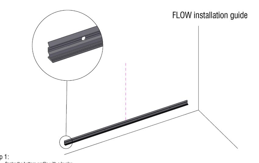
Safety Requirements

Safety Requirements

Flow - Wall Mounted Dry Erase Board,                                Verify Wall Construction
Non-Seismic Applications                                            CAUTION! Adequate wall construction is
                                                                    required to support the weight of the board.
The building’s Engineer of Record must be
                                                                    Minimum wall construction must be capable
consulted to determine if there are any seismic
                                                                    of supporting weight amounts listed in Table
requirements.
                                                                    1 on page 12.

                                                                  Minimum Required Wall Construction
                                                                  Drywall with metal studs:
                                                                     •     Must be at least 0.6 mm (.02”) thick Metal
                                                                           stud 48.8 mm x 50 mm (1.92” x 1.97”)
                                                                     •     Studs on maximum 600 mm (24”) centers
                                                                     •     Must be at least 2 x 12,5 mm (.49”) Type X
                                                                           gypsum drywall
                                                                     •     35 mm (1.34”) drywall screws on 250 mm
                                                                           (12”) centers

                                                                  Drywall with wooden studs:
                                                                     •    Stud grade SPF, DF-L or Hem-Fir 45 mm
                                                                          x 70 mm (1.5” x 3.5”)
                                                                     •    Studs on 600 mm (24”) centers
                                                                     •    Must be atleast 25 mm (5/8”) thick Type X
                                                                          gypsum drywall for the US or 2 x 12,5 mm (1/2”)
                                                                          for EU
                                                                     •    35 mm (#6 x 1-1/4”) drywall screws on 250 mm
                                                                          (12”) centers

                                                  Doc #100218 | Rev A | Page 3 of 16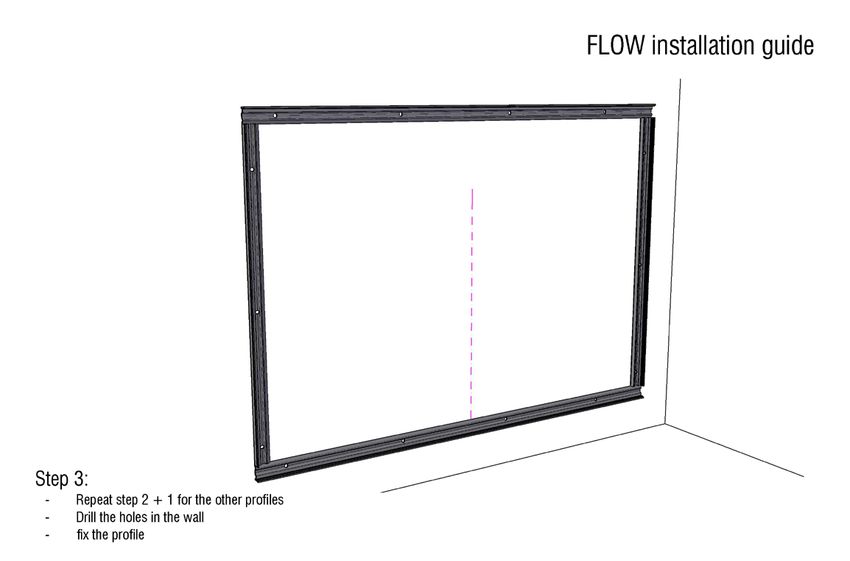
Handling + Storing of Panels

Handling + Storing of Panels
Handling
 •    When Polyvision panels are shipped, they are
      protected by craft paper or a self-adhesive
      transparent polyethylene film. Keep panels in the
      original package until installation.
                                                                   Storing
 •    Handle with care to prevent damage.
                                                                     •     Keep panels dry and free of debris.
 •    Never slide panels off the stack during handling.
      Panels should always be lifted and moved in a                  •     Store panels inside temps 50-90 °F (10-32 °C).
      vertical position.                                             •     Any panels stored outside should be protected
 •    Never place an Polyvision panel in a vertical                        from inclement weather conditions.
      position on the floor. This is to prevent damage
                                                                     •     Place panels on hard, flat surfaces that are not
      to the edges.
                                                                           subject to standing water.
 •    Prevent dirt from settling on and between panels
                                                                     •     Polyvision panels should be stacked no more
      to avoid surface damage, scratches or defects.
                                                                           than three high.
 •    Follow all safety instructions regarding personal
      protection when processing the panels.                         •     Panels should never be stored vertically or in
                                                                           such a way that the corners are vulnerable to
 •    Protect panel surface against sawdust and
                                                                           damage.
      sparks (metal particles).
 •    Polyvision panels will chip when cut or drilled
      with power tools. Hand-cutting can cause
      chipping up to approx. 2 mm from the edge.                     If you have a problem, question, or a request, call
      When chipping is in excess of 2 mm, please                     your local fabricator, your regional sales manager
      check the state of cutting tools and check that                or Polyvision Customer Service. Polyvision’s global
      the panel is adequately supported and clamped                  customer service team can be contacted on
      to prevent it from vibrating.
                                                                     Polyvision.com.
 •    All cut or drilled sections should be protected
      against humidity with PVC tape and/or by
      covering/sealing profiles or sealing washers.
 •    For detailed processing instructions, please refer
      to the panel processing instructions.

                                         Doc # 100218 | Rev A | Page 4 of 16
Required Materials + Equipment

Required Materials + Equipment
Electrical Equipment
 1.       Drill
 2.       Miter saw
 3.       Grinder
 4.       Jigsaw
 5.       Industrial vacuum cleaner

Hardware Equipment
 1.       Level (laser level recommended)
 2.       Aluminum straight guide
 3.       Chalk line
 4.       Anchors adapted to wall
      •       For gypsum walls, use #8 plastic wall anchor with #8 x 1-1/4” (4 mm x 35 mm) self drilling screws.
      •       For stone walls, anchors and screws must be provided by installer per conditions
      •       Recommended anchor spacing is 406 mm (16”) to 610 (24”) on center
 5.       Shims 1 mm - 2 mm - 3 mm (1/32” - 1/16” - 1/8”)
 6.       Soft wood block ± 50 mm x 25 mm x 300 mm (2” x 1” x 12”) length or rubber mallet to knock in the coverstrip
 7.       Glass suction cup lifters (2)

Included Hardware
 1.       Anchors
 2.       Screws

                                                         Doc #100218 | Rev A | Page 5 of 16
Key to System Details

Key to System Details
The details listed in the image below show placement for panel profiles and how the material can be
installed. IMPORTANT: Profiles must be secured to studs in as many locations as possible and at least
24” o.c. for horizontals and 18” o.c. for verticals.

Standard Extrusions

                 Mid Frame                              Base Frame                    Top Frame

                                         Doc # 100218 | Rev A | Page 6 of 16
Standard Extrusions

D2 | Panel Head at Ceiling
                                                                    structural support max
                                                                    24” o.c. (by others)

                                                            type S bugle head screws
                       mid                                  @ 16” o.c. (by erector)
                      frame

                       CeramicSteel                            factory edges on both panels
                       interior panels
                              panel dimension               panel dimension

                                                     Grid

D2 | Panel Head at Ceiling

                                                                 top frame

                                                                             gypsum board plug or screw
                                                                             if located over stud

                                            Doc #100218 | Rev A | Page 7 of 16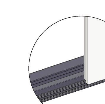
Standard Extrusions

D3 | Panel Terminator at Wall

                                                       structural support max
                                                       24” o.c. (by others)

                                                                type S bugle head screws
                                                                @ 16” O.C. (by erector)
                       base
                       frame

                                                                CeramicSteel
                                                                interior panels
                                                        top frame

D4 | Panel Bottom Line

                                                                    gypsum board plug or
                                                                    screw if located over stud
                      CeramicSteel
                      interior panels

                                                               base frame

                                    Doc # 100218 | Rev A | Page 8 of 16
Installation

Installation

Before starting the installation of Flow
  1.       Verify that the required equipment is available and material provided is accurate.
  2.       Provide adequate protection for finished floor surfaces.
  3.       If cutouts are required for electrical outlets or switches, refer to the following
           instructions
       •      Square penetrations for light switches and electrical outlets can be made by                              Table 1
              first drilling a pilot hole and then cutting with a jig saw using a metal cutting
                                                                                                          Product        Weight (kgs/lbs)
              blade minimum 14 TPI (teeth per inch).
                                                                                                          Flow 1220       18,7 kgs / 41 lbs
       •      All cutouts should be made with the finish side up, through the protective
                                                                                                          Flow 1830       28 kgs / 61.7 lbs
              polyfilm and a layer of common masking tape. Apply masking tape to the
                                                                                                          Flow 2420       37 kgs / 81.5 lbs
              entire area. Be sure to apply enough to protect the surface from the baseplate
              of the saw.
       •      Metal burrs left after cutting can be removed with a file or fine sand paper.

Step One
  1.       Start with a leveled line for the bottom profile. A laser level is recommended. Be sure to allow a
           minimum of 3 mm (1/8”) space between the profile and the wall base molding.
  2.       Mark and drill the holes in the wall.
  3.       Attach the base frame using the provided anchors. Refer to Table 2 for profile dimensions.

                                                                                                      Table 2
                                                                                                Vertical Orientation
                                                                                    Panel      Qty                 Profile Length
                                                                                   1 Panel      2                1195 mm (47 1/16”)
                                                                                   2 Panel      2               2380 mm (93 11/16”)
                                                                                   3 Panel      2               3565 mm (140 5/16”)
                                                                                   4 Panel      2                 4750 mm (187”)
                                                                                               Horizontal Orientation
                                                                                 Wall Length   Qty                 Profile Length
                                                                                        12’     2                3670 mm (144 1/2”)
                                                                                        14’     3                4280 mm (168 1/2”)
                                                                                        16’     2               4850 mm (190 15/16”)
                                                                                        18’     3               5500 mm (218 15/16”)
                                                                                        20’     3               6090 mm (239 3/16”)
                                                                                        24’     3               7270 mm (286 3/16”)
                                                                                        30’     5               9160 mm (360 5/8”)

                                                   Doc #100218 | Rev A | Page 9 of 16
Step Two
 1.    Start with a leveled line for the vertical profile (base frame). A laser level is recommended. Be sure to
       allow a minimum of 3 mm (1/8”) space between the profile and any existing wall.
 2.    Mark and drill the holes in the wall.

                                                                                                  Vertical Trim Lengths
                                                                                            Product        Inch       mm
                                                                                            Flow 1830   69 - 11/16    1770
                                                                                            Flow 2420    92 - 7/8     2360
                                                                                                 Horizontal Trim Lengths
                                                                                            Flow 1185    44 - 1/4     1125

Step Three
  1.   Repeat steps 1 and 2 for top and adjacent base frames.
  2.   Mark and drill the holes in the wall

                                                     Doc # 100218 | Rev A | Page 10 of 16
Installation
Step Four
1. Before installing the first panel, locate the panel with the logo in the bottom right corner. (Note that the logo
is not drawn to size.) This panel will need to be the furthest right panel. This installation guide shows the
logo panel as the first to be installed. Installation flows from right to left.
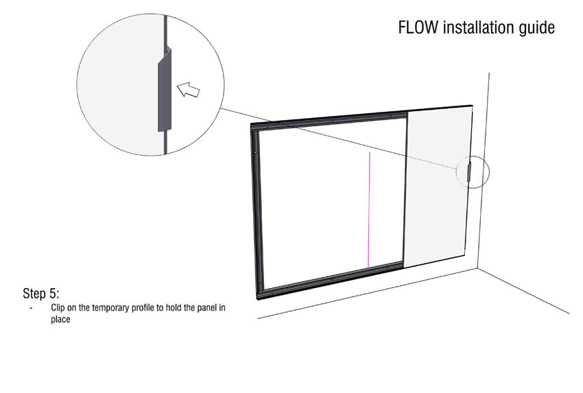
2. Place the first panel (with logo) into position and hold the panel into position with a temporary piece of
cover trim 8” (200 mm). The panel must fit against the vertical end profile and the horizontal bottom profile.
Cut pairs of Snap in Trim Extrusion, 8” (200mm) long with 45 mitre at one end. These can be used to
temporarily hold the first panel until the Vertical Joint Spline is installed and secured.
Doc #100218 | Rev A | Page 11 of 16Step Five
1. Insert the mid frame (H-profile) into the vertical side of the panel opposite from the vertical end
profile by sliding the metal extrusion into the groove on the side of the panel.
2. Depending upon the type of wall, either anchor directly through the flat part of the H-profile or
predrill the wall for the appropriate type of anchor.
Step Six
1. Repeat step 5 for the remaining panels
2. Place the final panel into position and hold in place with a temporary piece of cover trim 8” (200 mm).
Doc # 100218 | Rev A | Page 12 of 16Installation
Step Seven
1. Place the temporary snap on cover trim pieces on each end of the verticals.
2. Measure and miter cut the top and bottom cover trim (top frame).
3. Place snap on cover trim being sure to install using a piece of soft wood blocking or a rubber mallet
in order to avoid damaging the exposed finish. Start the profile aligned with the bottom/top of the
panel. Once thenprofiles are fixed they will be difficult to remove without damaging.
Doc #100218 | Rev A | Page 13 of 16Step Eight
1. Measure and miter cut the vertical cover trim (top frame).
2. Place snap on cover trims being sure to install using a piece of soft wood blocking or a rubber mallet
in order to avoid damaging the exposed finish. Start the profile aligned with the panel. Once the
profiles are fixed they will be difficult to remove without damaging.
Step Nine
1. Installation for Flow is complete.
Doc # 100218 | Rev A | Page 14 of 16Collaborative Products Warranty
CeramicSteel Surface: Forever warranty
Polyvision warrants that all porcelain-enameled surfaces and/or products made with
CeramicSteel will retain will retain its writing and erasing qualities and maintain its gloss
variance and color consistency for the life of the building or for as long as the product is in use,
whichever comes first.
Panel Construction and Mobile: 10 year limited warranty
Polyvision warrants that our panels, under normal atmospheric conditions and when sealed
from moisture, will not delaminate from the substrate or warp for a period of 10 years. Polyvision
warrants that our Mobile products, when used under normal conditions, will perform as
intended for a period of 10 years
Accessories: 2 year limited warranty
Polyvision warrants that our accessories, including but not limited to Collaborative ToolBar
and round magnetic eraser, when used under normal conditions will perform as intended
for a period of 2 years. Consumables like markers and chalk sticks are not covered by the
Accessories warranty
Alternative Materials: Limited Warranty
Polyvision warrants that our glass products, including but not limited to glassboards, when used
under normal conditions will perform as intended for a period of 5 years. Manufacturing defects
are warranted for a period of 5 years. Polyvision warrants that our tackable products, including
but not limited to Tac, when used under normal conditions will perform as intended for a period
of 2 years. Tackable products are warranted under the conditional terms of interior use only.
Should any failure to conform to this warranty become apparent, then, upon written notice
from the customer, Polyvision, at its option, will correct such nonconformity by repair or
replacement. Correction in the manner provided above shall constitute a fulfillment of all
liabilities of Polyvision with respect to the quality of the CeramicSteel. The warranty is applicable
only under normal usage and maintenance and does not cover defects caused by improper
handling, vandalism or abuse, or arising from failure to follow Polyvision’s instructions and
recommendations for maintenance.
The warranty is voided if any modifications are made to the products by the customer or other
trades with or without Polyvision’s written consent or prior knowledge. The warranty does not
include the cost of removal or reinstallation. This warranty is effective as of July 12, 2019, and
supersedes the terms and conditions of all prior surface warranties issued to the customer by
Polyvision.
This limited warranty is the sole remedy for product defects and no other express or implied
warranty is provided, including but not limited to any implied warranties of merchantability
or fitness for a particular purpose. Polyvision shall not be liable for consequential or
incidental damages arising from any product defect.
Doc #100218 | Rev A | Page 15 of 16Polyvision Americas Polyvision Europe Polyvision Asia-Pacific
10700 Abbotts Bridge Road Zuiderring 56 15th Floor, Kinwick Centre
Suite 100 3600 Genk, Belgium 32 Hollywood Road, Central District
Johns Creek, GA 30097 USA Hong Kong
T +32 89 32 31 30
T 1 888 325 6351 E EMEAsupport@Polyvision.com T +852 2520 0160
E info@Polyvision.com E APACsupport@Polyvision.com
©2022 Polyvision Corporation. All rights reserved. Trademarks used herein are the property of Polyvision
Corporation or of their respective owner. Polyvision Corporation reserves the right to make changes
in product design, construction or detail, and to discontinue any product or material without notice.
Polyvision.com 02-18-2022You can also read