Formula 1 20192019 European season starts here - Leading-Edge Motorsport Technology Since 1990 - The Chelsea Magazine Company
←
→
Page content transcription
If your browser does not render page correctly, please read the page content below
Leading-Edge Motorsport Technology Since 1990

                Formula1
                     2019
                 European season
                                 starts here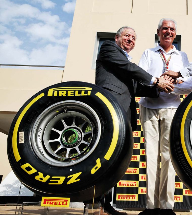
30 & 31 October 2019 | NEC, Birmingham

The UK’s largest annual gathering of
OEMs and engineering supply chain
professionals

        91%
     of exhibitors met their
                                             88%
                                         of exhibitors have either
                                                                                       98%
                                                                                   of exhibitors were satisfied
   objectives of networking             booked or will be booking                   with their experience at
  with new and existing clients               again for 2019                      Advanced Engineering 2018

                                                   Secure your stand today

       “We have done this for the 5th                                “I found the event a great
       year in a row and it is a very                                networking opportunity to meet
       good event for us to meet new                                 industrial professionals from
       clients.”                                                     different backgrounds with
       Thomas Evans, Business                                        different products.”
       Development Manager,
                                                                     Kat Clarke, Wing Manufacturing
       EBS Automation Ltd
                                                                     Engineer, Airbus

Secure your stand now
www.advancedengineeringuk.com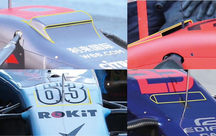
CONTENTS

                                                                                                                   5       Reverse thinking
                                                                                                                           Ricardo Divila asks why racecars still
                                                                                                                           have mirrored glass?
                                                                                                                   7       Complicated matter
                                                                                                                           Pirelli’s tyre structure under Mike
                                                                                                                           Blanchet’s microscope
                                                                                                                   8       Aero gain in Spain
                                                                                                                           One quarter of the way through
                                                                                                                           2019 F1 has upgrades aplenty
                                                                                                                   14      S-Duct
                                                                                                                           We uncover the real reasoning
                                                                                                                           behind this clever aerodynamic trick
                                                                                                                   18      Skirting the issue
                                                                                                                           Simon McBeath applies CFD to skirts
                                                                                                                           in Formula 1 to see what happens
                                                                                                                   26      Pirelli
                                                                                                                           We look at the challenges faced by
                                                                                                                           Pirelli for 2020, and for 2021
                                                                                                                   32      The India formula
                                                                                                                           The CFD model that shows future
                                                                                                                           thinking for F1 2021
                                                                                                                   Produced by Racecar Engineering team

Danger zone
A
             s we near ever closer to the ‘revolutionary’ 2021 season, details are   constructors limited to just four in number. Your average F1 fan may not get
             emerging of the proposed regulations which are steering F1 into         excited about today’s intricate wheel rims which utilise the hot air coming
             uncharted waters. In addition to the controversial budget caps,         from the brakes to heat the tyres to go a tenth of a lap quicker, but the DNA
             tenders are now out for single supply transmissions, wheel rims         of F1 is the ‘pinnacle of technology’ and the move towards single suppliers is
and brake systems too. In the battle between controlling the cost and using          threatening this philosophy, and taking the concept of innovation with it.
the sport to develop technology, it seems that the former is favoured.                   Currently, there are four manufacturers of brake caliper in F1, each pushing
    Having previously worked at Manor Racing, I fully appreciate the efforts to      the limits of their capability and driving innovation to develop a better
try and reduce costs to make the F1 championship more sustainable for the            product than their competition in a battle to supply more teams. If you cut
smaller teams. With the collapse of Manor at the beginning of the 2017 season        that down to one manufacturer, not only do you adversely affect the other
and the likes of Sauber, Racing Point (previously Force India) and Williams          three in terms of their business, but that drive for pushing the boundaries
either saved by title sponsors, buy outs, or clinging on to a sponsorship deal,      evaporates. Look at the result of the decision to select a single tyre supplier for
the era of the small F1 team is on life support. This is sub-optimal.                Formula 1. I agree, a tyre war is an expensive initiative, but the Japanese cope
    Without such teams, there is nowhere for young engineers, mechanics              in GT500, and what motivation do Pirelli have to keep developing their F1
or drivers to develop their Formula 1 experience. Formula 2 teams are                products when their business is secured for the next three years?
having to expand and become small F1 teams themselves in an attempt to                   Also, how much of a performance differentiator are brake calipers? Andrew
soak up young engineers who want to make that jump into the top tier, a              Green, Technical Director at Racing Point says that on the list of performance
jump which is getting ever bigger. Of course, companies such as Williams             differentiators, calipers are pretty low down. Furthermore, he reckons that the
Advanced Engineering, McLaren Applied Technologies and Red Bull Advanced             tender will struggle to produce calipers cheaper than Racing Point already
Technologies are an excellent development area for engineers, but with the           does. So, if the tender for brake calipers won’t significantly affect on-track
upcoming resource restriction in F1, we will undoubtedly see these companies         action or reduce costs then the only thing it is achieving is putting engineering
increase in number. However, these offer little trackside experience.                companies out of business and sacrificing innovation. The FIA and FOM have
    In an attempt to encourage more teams to remain sustainable in Formula           a difficult task ahead of them, and their decisions will please only some. But
1, and equalise the performance and therefore competition between the                this relentless drive towards standardisation could put the top tier of
teams, the FIA are aiming to slash costs through limiting access to the sport        motorsport in jeopardy, along with many companies within its supply chain.
via a tender process to supply all teams. However, these cost cutting measures
are going to significantly affect innovation and opportunity; you don’t need         GEMMA HATTON
to look far to find just that in Le Mans Prototypes with the LMP2 chassis            Deputy Editor

                                                                               RACECAR ENGINEERING FORMULA 1 SUPPLEMENT www.racecar-engineering.com 3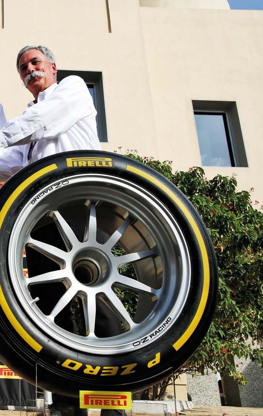

STRAIGHT TALK – RICARDO DIVILA

                         Don’t look back in anger
                          Why do racecars still use such old fashioned technology to provide a rear view?

R
         ay Harroun, an engineer born in 1879                 The knee-jerk reaction from the organisers was             It proved so useful and practical that it turned
         who was nicknamed the ‘Little Professor’,        to specify that the LMP2s had to have moveable             into a no-brainer for all racecars built by Nismo
         maintained he only really raced so as to         mirrors to shift the focus from the overtaking and         since then. The added bonus was the auto-dim
observe his designs being tested in the field.            blinding LMP1s, but it only made things worse; the         feature for the Suzuka 1000km race, which ended
    In 1911, for the inaugural Indianapolis 500-mile      vibration moved on to new heights of blur. Okay,           in darkness. Audi brought its version out to much
race, of the entire 40-car field his yellow Marmon        part of it was inadequate mountings to damp or             fanfare in 2012, much to my amusement, as we
– AKA the Wasp – was the only car to have just            restrain the housings, plus they were mandated to          had used that solution for 14 years by then.
one person on board. All the others had a riding          be bigger; so more aero turbulence and drag.                   It was also a primary item on the Deltawing for
mechanic, a bit of a tradition from the previous              Despite changing the mounts, shapes and                Le Mans in 2012, a clean, mirror-less design with a
years of racing on open roads where the early             actuating mechanisms after the test day they still         camera mounted high on the rear fin relaying an
racing machinery, pretty much all prototypes, were        vibrated, so they eventually solved the problem            unobstructed rear view to the cockpit screens. We
prone to mechanical failure or punctures a long           laterally by presenting the cars at scrutineering,         were definitely annoyed when not only did the
way from any assistance. Incidentally,                                                                                              ACO insist on having the old style
in 1912 the riding mechanics were                                                                                                   mirrors but, adding insult to injury,
required by the rules and were then                                                                                                 demanded that the car run LMP2
mandatory until 1922, and then                                                                                                      size mirrors even when running in
returned again in 1930 until 1937.                                                                                                  the Garage 56, with supposedly
                                                                                                                                    unlimited rules. This added eight
Time to reflect                                                                                                                     per cent more drag, considerably
For that first Indy 500 the Wasp also                                                                                               slowing the car in a straight line.
featured a rear-view mirror, one of
the first times such a device had                                                                                                  Looking ahead
been used – this was inspired by                                                                                                    There is now software that has
a solution to traffic management                                                                                                    motion sensors that can put a
Harroun had seen on a horse-drawn                                                                                                   coloured arrow pointing to the side
taxi some years earlier when he had                                                                                                 of the car an opponent is coming
worked as a chauffeur in Chicago.                                                                                                   up to pass. It flashes faster if the
     In winning that first Indianapolis                                                                                             overtaker is closing up fast and
                                         XPB

500, Harroun actually had a secret,                                                                                                 changes colour from green to red. It
which he related over 50 years later,           The trick mirrors on the 2018 Ferrari were as hi-tech as these parts can be,        wouldn’t pick up vampires, for as we
in 1967. His innovative mirror had              but should reflective glass really have a place on a modern Formula 1 car?          all know, they cast no reflection, even
reassured his rivals that the racing                                                                                                electronic, but all else is signalled.
would still be safe, despite him being alone in               then siliconing the mirrors in for practice and the         So, when these days we can have cameras
the car. But the race track at the speedway was               race. No more adjustable mirrors but no more            guiding us into our parking slot, why not have
a jarring, bumpy ride; it was, after all, made of             vibration either, or at least back to the usual.        the same sensing and warning about traffic and
bricks. ‘To tell you the truth, on the brick surface, I           Now, over a century after Harroun’s innovation,     dispense entirely with 1911 technology; those
couldn’t see a damn thing in it,’ Harroun said of the         we still use mirrors to see behind racing cars. Why?    draggy, vibrating, limited mirrors?
mirror. ‘And no one knew it but me.’                                                                                      Or why not go the whole hog and throw away
     This is actually similar to what we still have       Mirror finish                                               the dodgy mirrors and affix a full width OLED
today. Some rear view mirrors vibrate so much                 In 1998 I was involved in running a Nissan GT500        screen to the Halo, electronically enhanced to
that the driver can only see something moving                 car in Japan, and one of the corollaries of having a    highlight approaching racecars. It can even solve
behind him, but not very clearly. And then there              firewall blocking off the 100 litre fuel tanks behind   arguments when cars clash, just by recording all
is night racing and the problems that that can                the driver was having a small Perspex aperture          that is seen on the screens.
present. The ultimate was Audi’s new laser lights             for the central mirror that didn’t give us a wide           If you don’t like the Halos there’s another
with an estimated zillion candlepower fitted to the           enough field of view out the back of the car.           alternative, go further and have the view projected
R18. It was so bright that drivers being overtaken                The solution was to fit a rear view camera          directly on the driver’s retina from a projector
were complaining about being blinded. They lost               to replace the mirror, and a screen on the dash,        on the helmet. Or what about having enough
perception of the depth of field, their cockpits              easily done as one of the team sponsors, which          cheap smartphone derived cameras and having a
filled with such light from the frantically flashing          was a Nissan subsidiary, was a pioneer in the           360-degree view around the racecar?
following Audis. Even the trackside marshals were             manufacture of rear cameras for parking, now a              We have the technology, software and
getting suntanned in the night stints!                        standard fixture on medium range cars.                  hardware. But maybe not the will.

  When these days we can have cameras guiding us into parking slots, why
     not have the same sort of thing instead of mirrors on racecars?
                                                                               RACECAR ENGINEERING FORMULA 1 SUPPLEMENT www.racecar-engineering.com 5
FAST
IS OUR
DNA

 Our knowledge ranges from WRC to Le Mans and
 24 Nuerburgring to Formula 1 and even Formula E.
 You want fast. You want reliable. You want CP autosport.

           DRIVESHAFTS                 SETUP WIZZARD         SAFETY CAGES       COMPLETE SOLUTIONS         COMPONENTS

 CP tech GmbH        Dornierstraße 7           T   +49 (0)2955/4849-500     sales@cp-autosport.com   www.facebook.com/cpautosport
                     33142 Büren / Germany     F +49 (0)2955/4849-950       www.cp-autosport.com     www.facebook.com/setupwizzard

AZ_FormulaE_102017_190x135mm_03ap.indd 1                                                                                 18.10.17 08:33
SIDETRACK – MIKE BLANCHET

                          KISS it better
                           Why the FIA’s list of requirements for F1 tyres is a masterpiece of over-complication

K
         ISS – Keep It Simple, Stupid – is a useful       still permitted to do). The heaviness of the hybrid-      2018 US GP, given the effect this has on today’s
         acronym. It is seldom applied, however,          engined cars and the torque being produced,               ultra-sensitive F1 cars, is really unacceptable.
         in F1. The FIA’s 2020 through 2023 F1            plus the increasing downforce also added to their              Coming back to the geek in the darkened
tyre supply tender document is as far away from           problems. However, similar issues confront other          room, the FIA’s tender document was littered
that desire for simplicity as one could imagine.          tyre manufacturers in IndyCar and especially LMP1         with extraordinarily precise requirements such
It comprises 19 pages, of which only six and              and such problems have not been evident.                  as peak cornering force per degrees of slip angle
a bit cover contractual matters. The new tyre                                                                       for different types of corner; tyre stiffness versus
requirements that comprise the remainder appear            Slick and tyred                                          temperature working range; deviation of grip
as if some analytical geek in a darkened room,            Being the one-make supplier, one would think that         under a particular condition of surface macro and
hunched over an array of books and downloads              Pirelli’s job should be a little easier, but its approach micro roughness; glass transition temperature;
on every aspect of tyre design, materials, chemical       – not always with a free hand, it has to be said – has    degradation to 10ths/sec at 10, 18 and 22 per cent
properties and molecular structures, drew these up,       varied dramatically. Ranging from tyres that ‘fell        of race distance; cross linking of the compound
and they have no relevance to real-world racing.          off the cliff’ partway through the race (early days)      polymers, and much more. Pity there wasn’t one
    Of course, this is surely not true. I                                                                                      that decreed attainment of much greater
have no doubt that the FIA has gone to                                                                                         slip angles without losing forward speed.
great pains to ensure that input from                                                                                          And then what amounts to a twitch of
race tyre manufacturers and teams                                                                                              steering correction in qualifying would
combined with loads of its own data                                                                                            not always be irritatingly described by
has played a large part in drawing                                                                                             commentators as a mistake, and a quality
up the specifications mandated. It is                                                                                          driver’s lurid opposite-lock corner exits
certainly long overdue that F1 has                                                                                             could be a delight to us all.
the tyres it deserves, to do justice to
the qualities of the chassis, PUs, drivers                                                                                    Tread carefully
and engineers now involved. Running                                                                                            Realistically, I don’t see how all these
at six seconds/lap below qualifying                                                                                            characteristics can be reliably and regularly
pace in the early stages of a race to                                                                                          met, let alone how this can be accurately
protect the rubber, even allowing for                                                                                          measured. Which are to be the benchmark
                                          XPB

fuel load, is hardly proper racing.                                                                                            cars and drivers, for example? The fastest,
    Pirelli, of course, has again won the Pirelli has retained its Formula 1 tyre contract but its race rubber will            or the slowest? Maybe this could be one of
supply contract. This is a near 150-year- have to meet a long list of performance criteria to keep the FIA happy              the reasons, apart from money and politics,
old company with an illustrious tyre                                                                                          why Michelin and Bridgestone apparently
manufacturing and competition record, supporting          or barely managed one flat-out lap in qualifying,         didn’t bid for the contract? Even in the 2018
many different forms of contemporary racing. In           to over-hard compounds described by drivers as            season, with all the experience and knowledge of
the early 1950s it was dominant in grands prix,           giving ‘no grip’. Perhaps being Chinese part-owned,       the previous seven years, Pirelli frequently failed
and has been sporadically successful since. It            managed by Italians, with race tyres made in Turkey       to deliver tyres that provided the key elements in
currently produces superb high-performance road           could be something to do with this?                       race strategy and tactics that were wanted. It’s very
products and is among the top five in the industry             But I mentioned lack of a free hand above.           difficult therefore to see how it will meet these
worldwide – which makes it a global giant.                Certainly Pirelli’s task has been complicated             stringent new demands. Most likely, it will result in
                                                          by confusing calls first from Bernie Ecclestone,          a fudge. Should the tyres not be delivering during
Under pressure                                            subsequently the FIA, concerning what was needed          2020, whichever way this is judged, it won’t be
At face value then, it’s surprising that Pirelli has      to enhance the show. Pretty unfair pressure, really,      possible to change supplier quickly anyway.
struggled so much since its re-entry to F1 in 2011.       from people who don’t fully understand what is                 Being bolt-on items, tyres are the quickest and
Early issues with chunking, overheating and               involved in meeting these demands. But it does            easiest go-faster solutions, thus their importance.
delamination, fragility over kerbs and wheel-to-          appear to me that the Italian supplier hasn’t (a)         They are also capable of contributing hugely to
wheel contact etc caused much controversy and             resisted such knee-jerk actions more strongly and         an exciting race, or to a boring one. Therefore,
led to the introduction of regulations concerning         (b) is lacking in its simulation tools and skills.        it is correct to make stipulations as to their
minimum tyre pressures. Pirelli had a fair argument            The latter shortcomings, combined with the           performance. The question is whether these are
for some of this when pointing out that teams were        near-disasters at Silverstone and Spa in 2013,            practicable and measurable and also if Pirelli can
acting recklessly in applying low pressures to gain       have doubtless spooked the company and it has             deliver. It is to be hoped so, because as already
a performance advantage and drivers were over-            been over-conservative since. To insist that teams        mentioned it is a great company and should be
abusing the track limits (as they are, unfathomably,      increase tyre pressures, virtually on the grid of the     doing better. F1 needs Pirelli to up its game.

                 I don’t see how all these characteristics can be reliably and
                regularly met, let alone how this can be accurately measured
                                                                               RACECAR ENGINEERING FORMULA 1 SUPPLEMENT www.racecar-engineering.com 7
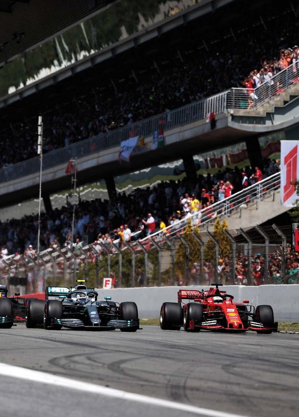
FORMULA 1 – BARCELONA AERO UPGRADES

Quarter
Masters
F1 teams have been updating their cars since the
start of the season, but the fifth round in Spain
saw the biggest aero changes of the year
By GEMMA HATTON

The Spanish Grand Prix is easily accessible for both team
members and parts suppliers, which makes step changes in
packages a little easier than at the fly-away races

8 www.racecar-engineering.com RACECAR ENGINEERING FORMULA 1 SUPPLEMENT
T
            he Spanish Grand Prix marks an            incorporating at least something new onto the       a change to your schedule you need to do it a
            important stage in the technical          car each race weekend. Take the example of          few weeks in advance and we’ve only achieved
            development of a Formula 1 car. After     this year’s pre-season testing where Mercedes       this because we have intensified our activities.
            teams have punched out the first race     popped out a new car for the second test alone!     It’s only down to a big team effort with everyone
version in time for Australia, teams transition       Apart from Mercedes, these race upgrades are        pushing hard to make up ground that we have
their efforts to developing the first major           usually one or two parts, such as a new front       been able to bring these developments forward.’
upgrade package which is usually scheduled for        wing, whereas in Spain, teams can arrive with       The power unit upgrade was accompanied by
Barcelona. Falling roughly a quarter of the way       upgrade packages which can consist of new           a new formulation of race lubricant from team
through the season, by early May teams have           front and rear wings, bargeboards, radiators,       technical partner Shell to further the PU gains.
had four races to understand the behaviour of         floors, suspension and engine upgrades.                  Haas on the other hand, will likely introduce
their car and establish areas of improvement.                                                             their Ferrari PU upgrade at either the Monaco or
    This usually leads to teams arriving in Spain     Second wind                                         Canada races. ‘I think doing it at the same time
with a significant aero upgrade package which         The latter was a key talking point at the Spanish   [introducing PU upgrades] is logistically very
they can test during the practice sessions and        Grand Prix, with Ferrari and all four Honda-        difficult for Ferrari,’ highlights Guenther Steiner,
decide on Friday night if they should run with        powered cars running their second specification     Team Principal at Haas. ‘Ferrari asked us if we are
them for the race. If not, they have time to revert   of power unit. Ferrari has been pushing hard to     ok with introducing it [the upgrade] one race
the changes before Saturday. Furthermore, it is       close the gap to Mercedes by bringing updates       or the other and as they need to manage the
also cheaper to send additional aero and vehicle      to the car earlier than scheduled. In Baku, they    engine mileage and all that stuff. There is no
dynamicists to Spain, who can help monitor the        introduced significant aerodynamic upgrades         point in us interfering and we are happy with
performance of these additional upgrades, and         one race early and arrived in Barcelona with a      what they have suggested.’
in the worst case scenario, spares can be sent        new power unit, two races ahead of schedule, as
out overnight, in time for qualifying.                this upgrade was originally planned for Canada.     Tunnel vision
    Traditionally, teams would bring major                ‘Having started the season in Melbourne         Teams are also targeting their resources at
upgrades to Barcelona, Canada, Silverstone and        we recognised that somehow we may have              making performance gains through vehicle
Monza, so a quarter, halfway and then three           been late on our performance compared to our        dynamic and aerodynamic upgrades. ‘We’re
quarters of the way through the season. But           competitors and we tried simply to push on all      constantly developing the current car and
as teams continue their rapid development             the main items where we were already planning       we’re aiming to produce upgrades as soon as
processes, technical upgrades are becoming            developments,’ highlights Mattia Binotto, Team      we’ve found gains in the wind tunnel,’ says Pete
an increasing occurrence with most teams              Principal at Ferrari. ‘When you are planning such   Machin, Head of Aerodynamics at Renault F1.

           Teams still arrive with significant upgrade packages which can
           consist of new front and rear wings, bargeboards, radiators,
           floors, suspension and engine upgrades

                                                                     RACECAR ENGINEERING FORMULA 1 SUPPLEMENT www.racecar-engineering.com 9
FORMULA 1 – BARCELONA AERO UPGRADES

The Mercedes W10 had modified bargeboards, consisting of three turning vanes instead of two as well as changes to the elements attached to the chassis, ahead of the sidepod

The car at the end
of the year will be a
couple of seconds
quicker than the
one that started the
season
     ‘We issue parts to the drawing office
and they see just how quickly they can get
them to the circuit. Obviously, it depends on          Under the skin of the SF90. Ferrari brought their 2nd specification of PU to Spain as well as an upgraded
the complexity of the parts and how long it            lubricant from Shell two races ahead of schedule in an attempt to close the gap to the two Mercedes
takes to design and manufacture. Certainly
in terms of the aero there is a lot of evolution
through the season and the car at the end of
the year will be a couple of seconds quicker
than the one that started the season as
aerodynamically things get a lot more
developed and tuned as the year progresses
and you improve your understanding.’
     Renault arrived in Spain with new parts on
their front wing, bargeboard and floor. ‘As the
first European round, Barcelona does offer a
good opportunity to bring a number of updates
to the car,’ highlights Nick Chester, Chassis
Technical Director at Renault F1. ‘Most other
teams will do the same, but we have a number
of reasonable upgrades that are positive. At
this stage there is a development race going on
between the teams, but we will keep pushing
hard to get the best from it each weekend.’
     In addition to the new aero parts, Renault
have also incorporated a few mechanical tweaks
in an attempt to improve the balance of the car.
Car balance and tyres are a particular challenge
for the teams as they transition from Baku,
which has the lowest energy input into the tyres,      The 2019 rules restrict the front brake duct inlet size and teams are now converging towards a teardrop shape
to Barcelona, which has the highest. This              as shown by the upgraded spec on the Racing Point RP19 (left) compared to an older version (right)

10 www.racecar-engineering.com RACECAR ENGINEERING FORMULA 1 SUPPLEMENT
FORMULA 1 – BARCELONA AERO UPGRADES
The parts we have are all out of date because we are updating
the car so quickly now, we don’t have all the spares we want
is mostly down to turns three and nine
which subject the tyres to huge lateral forces,
particularly for the front left which is why teams
often see high levels of graining.
Furthermore, turn three is at the beginning
of the lap, and so often the tyres are not up
to temperature and if the driver pushes too
hard, the surface of the tyre can be destroyed
resulting in a significant lack of grip by the
third sector of the track. The trick to Barcelona
is managing the tyres through turn three and
although this might sacrifice a tenth in sector
one, drivers can gain more time in sector three
by having their tyres in a much better condition.
‘Depending on the tyre temperature, track The Mercedes mirrors were mounted from the chassis swooping over the top of the mirror, forming an aerofoil shaped ‘hat’
temperature and other conditions there is a case
of managing the tyres around the lap,’ highlights
Dave Robson, Senior Race Engineer at Williams.
‘I think that’s always the case here. Sector three
is so sensitive to rear grip that there has to be
some amount of preparing the tyres because
there is so much lap time to be gained or lost
there. Preparing the tyres is a constant battle.
Look at everyone’s garages just before the
drivers go out everyone is doing different things,
whether that means nobody truly understands
or whether teams are just doing what suits their
car, their driver and their plan for the out lap.’
Back to back
To analyse the performance gains of all these
new parts, teams usually only fit these updates
to one of their two cars so that they can conduct
a back to back test between the new and the old
specification. They can then analyse the data on
Friday night after second practice and establish
if they should run with the updated package for
the remainder of the weekend.
‘If we put two cars with the new spec and
then we have an issue - is it the tyres or is it the
new spec?’ says Steiner. ‘We will consciously
have a back to back comparison not to confuse
us more with the tyre issue, and then if all goes
to plan we will convert the second car to the
new package on Friday night, as we cannot
change it over in the time between FP1 and FP2.’
The tyre issue that has been jeopardising Haas’ Just when you thought you couldn’t possibly incorporate any more winglets into an area, Haas has proved that you can!
season so far is the fact that they cannot seem to
get the tyres into the working window. of Spain meant that spares could be sent out so we don’t have all the spares we want, but it’s
However, sometimes teams opt for the and fitted in time for Saturday, which is one of for a completely different reason than last year.’
opposite strategy; running both drivers with the the reasons why teams prefer to introduce these With the first stage in each car’s technical
new updates. This was Racing Point’s plan for packages when the series returns to Europe. evolution now complete, teams will begin
the first two practice sessions in Spain, although ‘Last year, [this situation] would have been the next challenge of finding even more
this didn’t quite pay off as the team had initially much easier, because there wouldn’t have been performance gains, ready to implement into the
intended. With only a set of spares for the an upgrade on the car to start with,’ smiles next major upgrade package which will come
upgraded suspension, the damage caused by Andrew Green, Technical Director at Racing around the mid-point of the Formula 1 season.
Lance Stroll’s crash in FP1 meant that he couldn’t Point. ‘Do we have more spares now? Probably As this development battle continues, we will
run with the new bodywork in FP2, losing the not but for a completely different reason than start to see the grid converge and only then will
opportunity to gain invaluable data on the new last year. The parts we have are all out of date we get an indication of the optimum design
package. Luckily for Racing Point, the proximity because we are updating the car so quickly now, for these new 2019 regulations.
12 www.racecar-engineering.com RACECAR ENGINEERING FORMULA 1 SUPPLEMENTHigh Tech
ch | High Speed | High Quality
Pankl Systems Austria GmbH
Engine Systems
A-8600 Bruck/Mur, Kaltschmidstraße 2-6
Phone: +43(0)3862 33 999 0
Fax: +43(0)3862 33 999 290
e-mail: engine@pankl.com www.pankl.comFORMULA 1 PREVIEW – F1 S-DUCT
Seductive aero
The F1 S-duct is a clever aerodynamic trick that has been on Formula 1 cars since
2012. However, the details of how it works can be easily misinterpreted so we
spoke to F1 aerodynamicists to find out the real reason behind the S-duct.
By GEMMA HATTON
F
ormula 1 is embroiled in a battle to Whenever air flows over a surface, it loses underneath, and overall, the airflow under the
reduce the impact of aerodynamic energy, which causes the flow to slow down nose can become extremely turbulent. This
devices, but the introduction of and become turbulent. Therefore, once the flow not only feeds the main turning vanes
the S-duct in 2012 by Sauber, and now flow has travelled over the elements in the but also the leading edge of the underfloor.
widely adopted, goes to show how far the front wing, it becomes ‘dirty’. In particular the Therefore, the cleaner the teams can get this
understanding of aerodynamics has come gap between the underside of the nose, the airflow, the more performance they can extract
since. Much of the reasoning behind the device upper surface of the front wing and the inner from the other aero devices rearwards of the
has been misrepresented, so at pre-season faces of the front wing pillars can cause an nose such as the turning vanes, bargeboards,
Formula 1 testing, Racecar Engineering asked expanding tube of turbulent air. Add to this underfloor and the diffuser.
the question of the leading engineers; what is the fact that the air hitting the top corners of ‘The airflow under the nose is ‘dirty’ which
the S-duct for, and what does it achieve? the nose can also accelerate round and roll means it is a slower speed flow that has been
14 www.racecar-engineering.com RACECAR ENGINEERING FORMULA 1 SUPPLEMENTThe S-duct ingests ‘dirty’ airflow from under the nose via small NACA inlets (blue arrows) and distributes this flow into the cockpit via an outlet at the bridge of the nose
(green arrows). Here, the turbulent airflow has less of a negative effect on the overall aerodynamics, compared to flowing onto the turning vanes and the underfloor.
Sciencedirect.com
The geometry of the NACA duct is essential in order to achieve the necessary vortices which help to ingest air, even disrupted flow, efficiently
worked by the presence of the nose and the them to slow down also. As the air moves away dirty flow from under the nose through two
front wing,’ explains Arron Melvin, Principal from the surface, the molecules gradually pairs of NACA ducts and then release this flow
Aerodynamicist at Haas F1 Team. ‘To be legal, it increase in speed up to the speed of the main on top of the chassis, rather than letting it
is necessary to have certain nose volumes and flow. This thin layer of fluid where the velocity travel underneath the car,’ says Melvin. ‘If we let
inevitably there is a boundary layer growth due increases from zero at the surface to the free it go underneath the car, the lower speed flow
to the front wing and nose expansions. You can stream velocity is called the boundary layer, would arrive at the main turning vane, whereas
also get acceleration around the shoulder of and its thickness depends on the viscosity now it goes through the inlets, into the cockpit
the nose which leads to a high curvature flow.’ of the fluid and the characteristics of the and over the sidepod and does less harm. It is
When air flows over an object, the surface that it is travelling over. very much about where to place loss.’
molecules closest to the surface slow down, ‘We have introduced an S-duct for the first A NACA duct is a type of inlet which allows
which then causes the molecules just above time this year and essentially we ingest this the air to be drawn in with high efficiency and
RACECAR ENGINEERING FORMULA 1 SUPPLEMENT www.racecar-engineering.com 15FORMULA 1 PREVIEW – F1 S-DUCT
minimal drag. To achieve this, NACA ducts
are usually placed parallel to the local airflow
and in locations where the boundary layer is
relatively thin. The theory is that the shape
of these ducts encourage vortices to form,
reducing static pressure and enhancing the
efficiency of the flow through the inlet. As air
flows towards the narrow end of the duct, it
flows down the gentle slope and into the inlet.
But the air that approaches from outside the
inlet has to flow over the edges which causes
a vortex. This results in the formation of two
Simon McBeath & ANSYS
counter-rotating longitudinal vortices which
then induce more air to flow down the duct.
S-duct outlet
Quite often the S-duct outlet at the bridge of
An area of low static pressure can be seen at the edges of the duct (blue) as the rolling vortex is formed. the nose is misinterpreted as a device to help
avoid flow separation due to the angle change
from the steep nose to the flatter monocoque.
However, this outlet is simply about extracting
the dirty airflow to a place where it will do the
least damage to the car’s aero performance.
‘It’s a clear but ultimately relatively subtle
technology and for a small team such as Haas,
we had to be sure of the benefit to justify the
additional costs,’ says Melvin. ‘The nose is more
complicated to design and slightly heavier – it
is an aerodynamic vs structural trade-off.’
This design relates to the fact that the
air has to be channelled through the nose,
up to the outlet. But these channels have to
Simon McBeath & ANSYS
be incorporated in such a way that the nose
retains its structural requirements to pass the
FIA crash tests. This is the most likely reason
behind why not all teams have adopted this
technology. As mentioned above, this is the
The two longitudinal vortices along the edges of the NACA duct induce more air into the inlet, as first year that Haas are running with an S-duct,
demonstrated by the yellow sections of the streamlines as they decrease in velocity. and from pre-season testing, McLaren, Sauber
and Racing Point opted to run without it.
However, its effectiveness may prove to be
alluring for the teams this season.
The shape of these ducts enhances the efficiency of the airflow
There are a variety of designs for the S-duct outlet as shown here on the Mercedes W10 (left) and the Haas VF-19 (right) seen in pre-season testing in Barcelona
16 www.racecar-engineering.com RACECAR ENGINEERING FORMULA 1 SUPPLEMENTIntroducing the first f-POD designed
to be integrated Into your garage walling
We supply to:
Formula 1 - F2 - F3
World Endurance Championship
European Le Mans Series
Asian Le Mans Series
Indylites
Porsche Super Cup
Porsche Carrera Cup
Blancpain - European GT4 - V de V
British GT - British Touring Cars
Chinese Touring Cars - Korean TCR
Regional Formula 3 - Formula 4
- - -
Primary Designs are leaders in the design and
manufacture of world-class high performance exhausts
Suppliers to championship winning Formula 1 fabrication of thin wall exotic alloys makes
teams and world record breaking supercar us the ideal partner to design and build
manufacturers. Our knowledge of exhaust design, high-performance racing exhausts for an
alongside our expertise in the welding and extensive range of motorsport applications.
Tel: +44 (0)1844 216 057 Web: www.primarydesigns.co.uk Email: patbarrett@primarydesigns.co.ukTECHNOLOGY – AERODYNAMICS
Lifting the skirts
on ground effect
The Lotus 79 kick-started the ground effect revolution in Formula 1 following its dominant performance in 1978. It was also a very nice looking racecar
Modern Formula 1 aerodynamics are notoriously complicated
but was it really far simpler 40 years ago? We take the CFD
time machine back to the age of ground effects to find out
By SIMON MCBEATH
T
hey say that all race fans have It might also be argued that the appearance JPS-liveried Lotus 79, or one that had cleaner
favourite periods of racecar design. of ground effect and its successful application to lines than the Williams FW07?
This may have something to do with racecars in the late ‘70s and early ‘80s produced The chance, then, to do some CFD on a CAD
the cars one grew up watching. It another pure concept. Thanks largely to the model of a 1982 ground effect F1 car (which for
may be down to aesthetics. Or it may be work of a small group working for Peter Wright, now must remain anonymous in deference to
because of fascination with the engineering. this magazine’s technical consultant who was the owner’s wishes) was a great opportunity not
But one thing is certain, racecars are a lot more then in charge of the wind tunnel programme at only to examine how the aerodynamics on cars
complicated now than they once were. Team Lotus, beautifully integrated aerodynamic of that era functioned, but also to study what
Pre-aerodynamic aids (effectively pre-1967 packages that exploited a large proportion happened when things went wrong.
for single seaters) F1 cars were perhaps as of the plan area of the cars with an elegantly Sliding skirts along the outer, bottom edge
simple as they could be – you might use the simple yet highly potent principle became the of the sidepods (which had downforce-inducing
word pure instead of simple. However, once F1 norm for a few years. But the reader would be profiled undersides) were originally the key
engineers got a grip (no pun intended) on the correct if they were sensing writer bias here, so to maximising the underbody’s downforce
benefits that aerodynamics and specifically to be totally upfront about this, was there contribution. The objective was obviously to
downforce could bring there was no going back. ever a more beautiful Formula 1 car than the keep the spring-loaded skirts in full contact
18 www.racecar-engineering.com RACECAR ENGINEERING FORMULA 1 SUPPLEMENTAbove and right: Wind
tunnel models of the
Lotus 79 with the skirt
visible at the lower
edge of the sidepod
Sliding skirts along the outer, bottom edge of the
sidepods were originally the key to maximising
the underbody’s downforce contribution
with the ground at all times, but as history First, let’s take a look at the aerodynamic
Table 1: The coefficients on our ground effect F1
relates they didn’t always slide up and down performance of ground effect F1 cars from that
model compared to Team Lotus-based data
as designed. Sometimes a jammed skirt would period (they were banned at the end of 1982
CD -CL -L/D
see a car leave the race track at a tangent to the and flat bottoms between the axle lines on
intended curve, on occasion with disastrous Formula 1 cars became the norm). Our model 1982 CFD model 1.197 3.821 3.192
results. The high loads generated also brought looks to be representative for this purpose Lotus F1 ¼ scale 1.111 3.710 3.340
related engineering challenges, such as the thanks to some in-period supporting data.
need for improved brakes and beefed up Table 1 highlights the key parameters the data from different cars using different
chassis and suspension. So there were major derived from our baseline CFD run as simulation methods, both of which had or
issues surrounding these skirted cars. coefficients, with comparison with some figures have their individual shortcomings, provides
However, when the skirts were in full and from a 1983 technical paper by Peter Wright confidence that the qualitative effects we’re
consistent ground contact the cornering and at the same ride height and with skirts also going to focus on here have a sound basis.
braking power of these Formula 1 cars was in full contact (the data has been adjusted to CFD can do so much more than just enable
impressive, and the step forward in lap time represent notionally similar frontal areas). As the calculation of forces and trends though.
performance was very significant. can be seen the coefficients agree quite well Not only does it enable us to break down the
between those derived in CFD for this article total forces into the respective contributions
The questions and the typical data published by Wright, which of each major part of the car, it also allows us
So how did skirted ground effect work? What was obtained in the 5ft x 4ft Donald Campbell to visualise the pressures and flows around the
happened when the skirts jammed? And tunnel at Imperial College, London, on 25 per model, and easily to examine a few ‘what if’
what happened (aerodynamically) when the cent scale models of unspecified Lotus cars scenarios, such as ‘what if the skirts jam?’
regulators attempted to enforce a minimum between 1978 and 1982 (Types 78, 79 and 91 Once our model had achieved a satisfactory
skirt to ground gap in Formula1 in 1981? were mentioned). Such agreement between front to rear downforce balance, this then
RACECAR ENGINEERING FORMULA 1 SUPPLEMENT www.racecar-engineering.com 19TECHNOLOGY – AERODYNAMICS
enabled the distribution of the forces to be
Illustrations (S. McBeath/ANSYS unless otherwise stated)
calculated. The dual-element rear wing featured
a fairly flat, modestly cambered main element
and a medium-steep flap angle, while the
front wing was run at a shallow angle. This was
common practice in period if front wings were
needed. Sometimes cars would be run with no
front wing, although one suspects this would
probably be in circumstances that required
lower drag, hence lower rear wing angles, hence
the front wing could be dispensed with to
maintain the aerodynamic balance.
Then and now
Figure 1 shows the drag contributions of the
major components of our model alongside
similar data from our article in V26N12, which
(along with V27N1) featured a model created
to the 2017 F1 regulations by Miqdad Ali of Figure 1: Drag contributions of the major components of our 1982 ground effect model compared to 2017 rules F1 model
Dynamic Flow Solutions, used here as indicative
of the numbers on recent Formula 1 cars.
The 1982 car’s body created a much greater
proportion of the drag than was the case with
the 2017 model, and given that the body
width behind the front wheels has remained
constant at 1400mm since then, this in part
shows significant progress on drag reduction of
the main body (which includes the upper and
lower surfaces in this context), although it must
also be related to the lower proportion of total
downforce generated by the body. The 1982
car’s bigger wheels, unsurprisingly, were also
bigger drag contributors, but its wings made
smaller contributions, especially the front but
even the rear wing made proportionately less
drag than that of the 2017 car.
Figure 2 shows the downforce contributions
of the same component groups, and the Figure 2: This shows the contributions to downforce and lift from all the major car components for our two F1 models
contrasts between the 1982 and 2017 models
were even starker. The bigger wheels on the
older car generated more lift, partly because
of their greater width but also in the case of
the rear wheels because the long sidepod and
the presence of the side skirt forced more flow
over the rear tyres. The wings generated less
downforce on the older car, commensurate
with the lower wing drag contributions
highlighted above. But the biggest contrast
was in the downforce contributions of the car
body; when its skirts were in full contact over
95 per cent of the 1982 car’s total downforce
came from the body compared to around 47
per cent on the 2017 car. In passing it ought
to be said that the 2017 model (with no skirts
of course) achieved somewhat higher total
downforce than our baseline 1982 model for a
not dissimilar drag level, highlighting 37 years
of steady evolution in racecar aerodynamics to Figure 3: Pressure distribution on the underside shows where most of the downforce accrued on the 1982 skirted car
where we are today, for better or worse.
When the skirts were in full and consistent
In order to maintain our test subject’s
anonymity we are restricted to non-identifying
ground contact the cornering and braking
views such as the underside, but no matter
because this is where most of the interest
occurred. Figure 3 shows the pressure
distribution on our 1982 model’s lower power of these cars was very impressive
20 www.racecar-engineering.com RACECAR ENGINEERING FORMULA 1 SUPPLEMENTsurfaces and it is immediately clear where the
low pressure areas were generated. The front
wing, which featured an end-plate reaching
the ground to simulate a fixed skirt, exhibited
relatively mild suction. The rear wing generated
moderate suction, with variations across its
span thanks to the wake of the driver, cockpit
and roll hoop as well as those interesting flows
coming up and over the rear tyres. But it’s easy
to see how the main underbody generated the
vast majority of the car’s downforce, since this is
where the biggest pressure reduction was, and
it was spread over a large plan area. The suction
was concentrated in the forward underbody,
hence only a small front wing (at most) was
needed to balance the car. It’s also interesting to
note that although it was the tunnels either side
of the chassis that did the work, the pressure
Figure 4: The streamlines show a fast, clean flow through the underbody, with the front wheel wakes entirely outboard reduction they induced extended right across
the underside of the central chassis too.
In Figure 4 streamlines have been initiated
on a horizontal plane 50mm above ground level
to show the flow velocities below the car. Note
first that the ‘low power’ front wing created no
apparent inwash or outwash component. The
positioning of the tunnel entrances was such
that only clean flow converged between the
front wheels and entered the underbody while
the dirty front wheel wake remained entirely
outboard. The side skirts then ensured that no
influx from the sides into the underbody was
possible, and the accelerated flow in the forward
underbody was virtually two-dimensional,
remaining at high velocity (and therefore
at low pressure) right along the flat throat
region before then slowing down in the tunnel
diffusers. Because of the side skirts, sideways
Figure 5: The effect of skirt gap on the downforce, as reported by Peter Wright on quarter-scale Lotus models in 1983 influx only started at the rear of the sidepods,
in line with the front of the rear tyres, and aft
of this some of the rear wheel wake was drawn
into the flow, issues which would have greater
significance on subsequent skirt-less flat bottom
Formula 1 layouts with aft-mounted diffusers,
such as those we see today.
Skirting issues
Two different scenarios of skirt malfunction
could be envisaged; firstly, the simple case of a
horizontal gap beneath the skirt, as if it jammed
up but remained parallel to the ground; and
secondly, the case of the skirt being jammed at
an angle, either front-up or rear-up. Taking the
horizontal skirt gap first, Figure 5 shows the
reduction in downforce that Wright reported
on the quarter-scale Lotus models in 1983.
Our 1982 model also showed rapidly declining
downforce in this same scenario, although drag
Figure 6: Having no skirt (lower half) drastically altered pressure distribution on the underside. Full skirt is upper half altered very little with skirt gap, aspects verified
in real-world straightline track testing.
Not only had the suction in the underbody
Visualising how these big downforce losses
occurred is very revealing. Figure 6 shows the
throat been all but lost, but there was also slight
surface pressures on the CFD model’s underside
with no skirt at all in the lower half of image
compared to the fully skirted case. Not only
positive pressure about halfway along the tunnels had the suction in the underbody throat been
RACECAR ENGINEERING FORMULA 1 SUPPLEMENT www.racecar-engineering.com 21TECHNOLOGY – AERODYNAMICS
all but lost, but there was also slight positive
pressure about halfway along the tunnels. Over
such a large plan area this increase in pressure
represents a huge loss of downforce. Recall
that in 1981 the FIA temporarily banned side
skirts and mandated a 6cm minimum ground
clearance; it is perhaps no wonder that the
teams responded with some frankly ridiculous
ways of lowering the cars after their static ride
height checks in order to bridge the gap along
the bottom outer edge of the sidepods.
Figure 7 shows the streamlines again
projected on a horizontal plane level with the
underside, and by comparing with Figure 4 the
very different flow regime is apparent. Not only
did the removal of the skirt enable large scale
inflow from the sides that now preferentially
filled the tunnels, but it can also be seen that
in the first third of the tunnel the streamlines Figure 7: Removing the skirts significantly altered the flows under the racecar too. Compare this image with Figure 4
actually flowed outboard of the edge of the
sidepod. This was, no doubt, in response
to the tunnels filling from the sides further
downstream and to the obviously related slight
positive pressure halfway along the tunnels
mentioned above that all contributed to a much
reduced mean velocity through the throat. The
tunnels did still generate some downforce, at
the inlet and also where the vortex that spun off
the bottom edge of the sidepod created a drop
in pressure in the diffuser.
Wing effects
The keen-eyed reader will have also noticed in
Figure 6 that the rear wing appeared to show
increased suction on its underside in the model
with no skirt compared to the fully skirted case.
Indeed, there was a trend in the results that saw
increasing rear wing downforce with increasing Figure 8: With full skirt the front wheel wake couldn’t enter the underbody but it had a negative effect on the rear wing
skirt gap, and the wing generated 35 per cent
more downforce with no skirt than with the
full skirt. What caused this effect? Contrast the
predominant paths of the front wheel wake in
Figures 8 and 9. In Figure 8 it is clear that the
full skirt prevented the front wheel wake from
getting under the car, which in turn saw it turn
upwards and over the rear upper edge of the
sidepod ahead of the rear wheel. From here it
entered and adversely affected the flow field of
the rear wing, reducing the wing’s downforce.
In Figure 9, the absence of the skirt allowed
most of the front wheel wake to pass into the
underbody and much less (though still some) of
it went upwards to affect the rear wing.
So increasing the skirt gap or removing the
skirt entirely not only drastically reduced the
forward-biased downforce of the underbody
but it also increased the downforce of the rear
wing. This contributed to further rearwards Figure 9: With the skirt removed the front wheel wake entered the underbody, not encountering the rear wing so much
shifting of the overall centre of pressure that
It seems very clear then that any gap under
the massive loss of forward underbody
downforce had already created. As a related
the car’s skirt was quite a bad thing because
side note, some of the cars around this time
had a raised fence along the upper, rear edge
of the sidepod and from what we have seen
from this study this fence must have been to so much of the downforce was then lost
22 www.racecar-engineering.com RACECAR ENGINEERING FORMULA 1 SUPPLEMENTCFD Simulations ○ Consulting ○ Optimization
HIGH SPEED
Aero creates downforce... CONNECTIVITY
SOLUTIONS
MINIATURE
IP68 SEALED
LIGHTWEIGHT
RUGGED
RELIABLE
…downforce creates victories.
Standardized CFD simulations
CAD in → Report out
Fast, accurate, affordable
For more information about ,
OUR SOLUTIONS
or , please visit or contact us:
www.MantiumCAE.com ○ info@MantiumCAE.com
LP360TM: breakthrough connector
with 360° mating freedom
Signal & power, USB 2.0 and Ethernet
Robust, vibration-resistant design
Non-magnetic ball locking
- easy and quick to mate and unmate
MiniMax: ultra-miniature
USB 3.0 connector, 12 mm diameter
Ultra-compact and lightweight
Signal & power
Up to 10 Gb/s data transmission
Rugged Flash Drive for the
safe storage of sensitive data
Up to 100 MB/s read speed
Up to 128 GB memory size
Withstands corrosion, vibration,
Woodford Trailers Limited shock and extreme temperatures
14 Great Central Way
Daventry • Woodford Halse
Call +44 23 9245 9600
Northants • NN11 3PZ or email Sales@fischerconnectors.co.uk
Telephone: 01327 263379
fischerconnectors.com
Email: sales@woodfordtrailers.comTECHNOLOGY – AERODYNAMICS
Figure 10: This is the underside pressure distribution resulting from a front-up skirt jam Figure 11: The underside pressure distribution that is the result of a rear-up skirt jam
Skirts had their issues, but whether they could have ever been made
reliable became academic when flat undersides were mandated in 1983
steer the front wheel wake away from the rear the effect of a skirt jamming up at the front or rear, a ‘rear-up jam’. Again there was minimal
wing when full skirts were deployed. the rear? Two cases were run, one with the gap effect on drag but the downforce losses were
It seems very clear then that any gap under ranging from 45mm at the front to 10mm at the substantial in both cases. The more likely to
the skirt was a bad thing because so much rear, which we shall call a ‘front-up jam’, the other occur front-up jam saw very slightly less overall
downforce was lost. What then would have been ranging from 10mm at the front to 45mm at the downforce lost than the rear-up case, the latter
showing losses not far short of the no skirt case.
The visualisation of the front-up jam in
Figure 10 shows that the surface pressures on
the car’s underbody were generally lower than
in the no skirt case as shown in the lower half of
Figure 6, with an intensification of the vortex-
induced suction ahead of the narrowing skirt
gap. Hence the downforce loss in this instance,
while still drastic, was not as much as in the no
skirt case. Figure 11, showing the underbody
pressures in the rear-up jam case was more akin
to the no skirt case, although the presence of
the tilted skirt did cause some intensification
of the vortex that added a little more suction
to the forward diffuser region. In essence then
these jammed skirt scenarios were really just
variations of the no skirt case given the large
downforce losses and balance shifts.
Figure 12: Streamlines show the wake of our 1982 skirted ground effect Formula 1 model; note inwash near ground level
Future ground effect
Skirts certainly had their issues then, but
whether they could ever have been made
reliable became academic when flat undersides
were mandated in 1983, ultimately leading to
the rules we have now in 2019.
It has been said that ground effect cars were
able to run close enough to allow drivers to be
able to race each other, and Figures 12 and 13
show the wake in two different ways, revealing
central upwash that seemed to entrain much of
the rear wheel wake, and relatively clean inwash
behind the car. Figure 13 implies that at just
one to two car lengths behind the car the wake
at underbody level was not too badly disturbed,
possibly explaining how the cars could run
close. Maybe these, more than the 37-year-
old qualities of ground effect cars, are among
the current objectives of the FIA’s research
Figure 13: Wake on a plane 50mm above ground level narrowed significantly at just one or two car lengths behind model highlighted in the April issue of Racecar?
24 www.racecar-engineering.com RACECAR ENGINEERING FORMULA 1 SUPPLEMENTSkirts on a Group C sportscar
Table 2: The effects of fitting skirts
on a Group C Mazda 787B model
CD -CL -L/D
No skirt 0.426 1.909 4.478
Outer skirt 0.384 1.150 2.990
Inner skirt 0.368 0.995 2.704
Figure 14: Mazda 787B Group C model with skirt fitted.
The car, which famously won Le Mans in 1991, never
raced with skirts in period as these had been banned
S
kirts had long been banned when Group C
produced probably the highest downforce Figure 15: With no skirt the tunnels were partly filled by flow from sides, improving the underbody suction
levels seen on mainstream racecars. But
would they have enabled Group C prototypes to
have generated even more downforce? Readers
may recall that in V28N10 (October 2018) we
examined a model of a Mazda 787B replica in
1991 Le Mans-winning trim. By kind permission
of project owner Mark Peters the model has been
used again to examine the effects of skirts.
Skirts were first attached along the outer
edges of the car’s floor (Figure 14), then moved
inboard by 350mm. The results are compared
in Table 2 to the best run from our previous
article, which featured no skirt.
It is immediately apparent that this simplistic
approach has caused very significant reductions
in aerodynamic performance. Drag may
have reduced (by 10 per cent and 14 per cent
respectively) but downforce reduced by 40 Figure 16: This shows how the outer skirt cut off all the lateral influx which meant the diffusers stalled
per cent and 48 per cent compared to the skirt-
less model. Why was this?
Figure 15 shows streamlines under the car in
the no skirt case. The diffuser tunnels were being
filled partly by flow from the front and partly by
flow from the sides. The latter not only created
suction under the outer flat underside, it was
also being spun into large vortices in the tunnels
helping to maintain attached flow, which in turn
helped to pull high mass flow through the entire
system, resulting in high underbody downforce.
As soon as either skirt was attached the lateral
influx was cut off and the diffusers stalled, leading
to the reductions in downforce.
This is yet another example of how a device
that works on one type of racecar does not
necessarily work on another. Figure 17: Inner skirt also cut off most of flow from sides, causing even greater downforce reduction
RACECAR ENGINEERING FORMULA 1 SUPPLEMENT www.racecar-engineering.com 25You can also read