"From Sheets to Fields" - Cavity Manufacturing Techniques II CAS June 8-17, 2010 Denmark Hanspeter Vogel - CERN Indico
←
→
Page content transcription
If your browser does not render page correctly, please read the page content below
Cavity Manufacturing Techniques II
CAS June 8-17, 2010 Denmark
“From Sheets to Fields”
Hanspeter Vogel
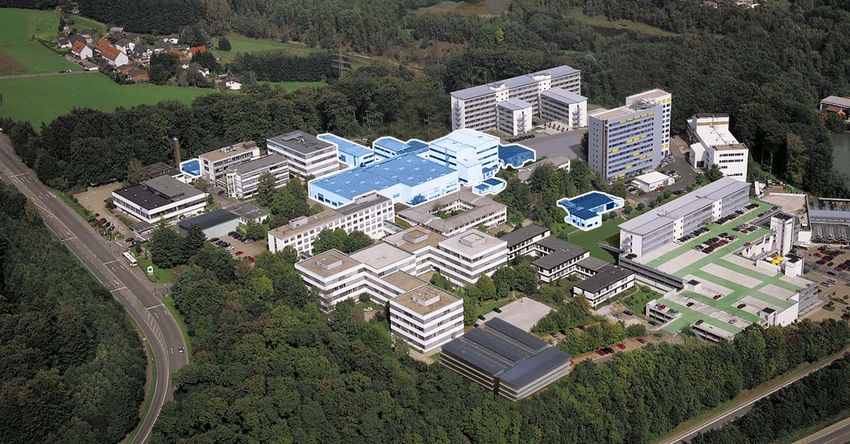
RI Research Instruments GmbH
Friedrich-Ebert-Straße 1
51429 Bergisch Gladbach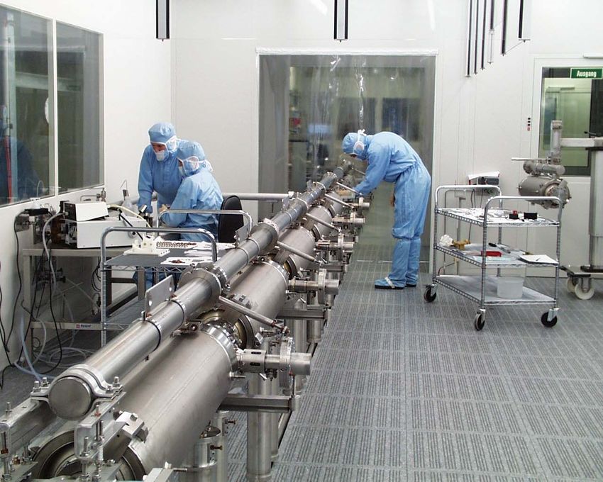
Advanced Technology Equipment and Turn-Key
System Supplier for Research, Industry and
Medical worldwide

RI Research Instruments GmbH is continuing the accelerator and special manufacturing business of
the former ACCEL Instruments GmbH from April 01, 2009.

                                                              • Linear Accelerators
                                                              • RF Cavities, Couplers, Auxiliaries
                                                              • Superconducting Accelerator
                                                                Modules
                                                              • Electron and Ion Sources
                                                              • Beam Diagnostic Elements and
                                                              • Particle Beam Lines
                                                              • Accelerator Equipment for Particle
                                                                Therapy
                                                              • Specialized Manufacturing Projects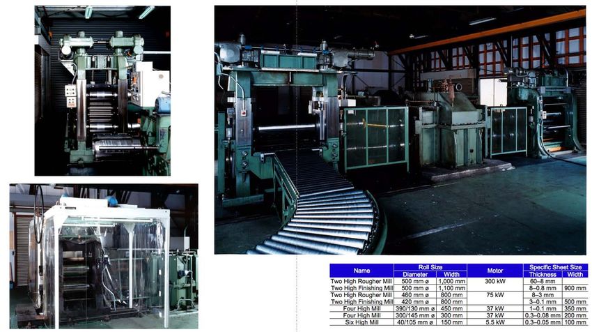
Content and Overview

 In this overview we concentrate on the manufacturing of superconducting rf (srf) cavities (and
 related auxiliaries) and show the process from the source of niobium material until the final
 installation of srf accelerating modules.

 •      Production of niobium for srf cavities         •   Cold rf test

 •      Forming niobium into shape                     •   Auxiliary components, coupler,

 •      Assembly and electron beam welding                 tuner, cryostat

 •      RF-control measurements                        •   Assembly of a srf module

 •      Completion of a cavity / helium vessel         •   Delivery and installation

 •      Final RF-adjustments                           •   Technical variants

 •      Surface preparation                            •   Acknowledgements

Hanspeter Vogel, CAS 08 – 17 June, 2010 Denmark
Some important properties of Niobium

                                                  • Niobium is a rare, soft, malleable, ductile, gray-white metal.
                                                  • The metal is inert to acids
                                                  • It tends to react with oxygen, carbon, the halogens, nitrogen, and
                                                    sulfur at low temperatures (
Nb mines worldwide

 • Tantalite (Fe, Mn)(Nb,Ta)2O6

 • Columbite              (Fe, Mn)(Nb,Ta)2O6

 • Pyrochlore             (Ca,Na)2Nb2O6F

 Pyrochlore is mostly used
 for the generation of high
 purity niobium due to its
 low TA-content                        St. Honore

                                      Catalão
                                                                                         Araxiá
  Imagumbai, et al: “Resource, production volume & manufacturing technology of niobium” Material Science & Technology Vol.72(2002)No.3 pp204-210

Hanspeter Vogel, CAS 08 – 17 June, 2010 Denmark
High Purity Niobium

    The Residual Resistivity Ratio (RRR) is the main parameter
    for characterization for the purity of Niobium
Impurity concentrate  (ppm)
                  Relationship between RRR and Impurities

  80 80                                                                       RRR
       70
                                                                              350350
  60 60
                                                                                   300

       50

                                                                          O
                                                                              250250
  40 40                                                                   N
                                                                          H                                                                                           RRR > 300
                                                                                                                                                                       RRR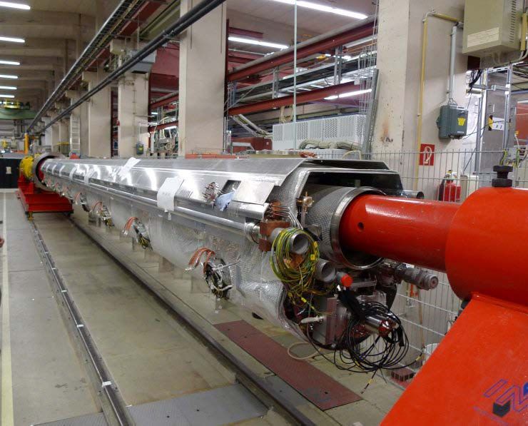
Production of niobium worldwide and high
 purity niobium consumption for accelerator
 manufacturing

70000                                                                            250

60000                                                                                                                               ILC
                                                                                 200
50000

                                                                                 150
40000

30000                                                                            100

20000
                                                                                  50
10000                                                                                                      XFEL
   0                                                                               0
   1960    1965   1970   1975   1980   1985   1990   1995   2000   2005   2010

                                                                                   05

                                                                                          07

                                                                                                09

                                                                                                      11

                                                                                                            13

                                                                                                                   15

                                                                                                                         17

                                                                                                                               19

                                                                                                                                     21

                                                                                                                                           23

                                                                                                                                                 25
                                                                                  20

                                                                                         20

                                                                                               20

                                                                                                     20

                                                                                                           20

                                                                                                                  20

                                                                                                                        20

                                                                                                                              20

                                                                                                                                    20

                                                                                                                                          20

                                                                                                                                                20
          world mine production (ton)                                                  word demand high purity (estimated) Nb (ton)

 Even large scale srf projects should be easily supplied with high purity Nb in relation with the
 world mine production

Hanspeter Vogel, CAS 08 – 17 June, 2010 Denmark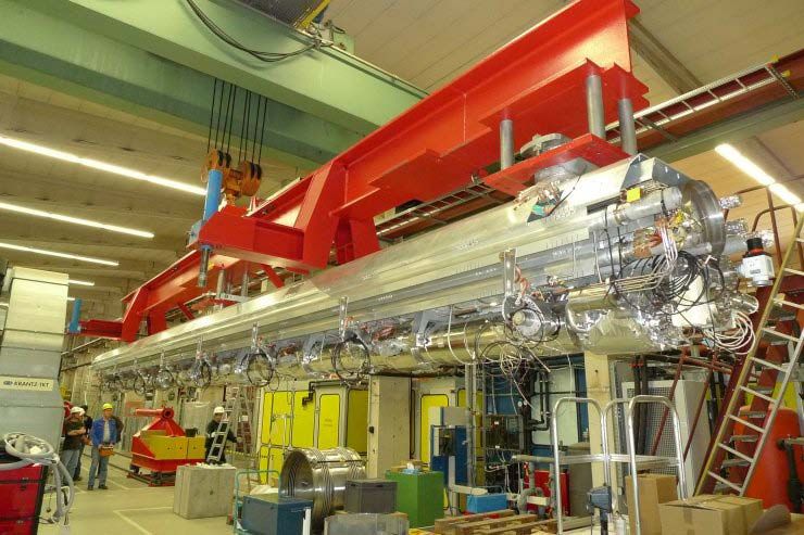
Fabrication process of Nb sheets for
 superconducting cavities (1)

Hanspeter Vogel, CAS 08 – 17 June, 2010 Denmark
Fabrication process of Nb sheets for
 superconducting cavities (2)

                                                  Nb ingot after
                                                  refining by
                                                  multiple
                                                  electron beam
                                                  welding in
                                                  vaccum*

Nb sheets ready for cavity
production*                                                   sheet rolling installation*

                                                                                  * Courtesy by Tokyo Denkai Co Ltd.
Hanspeter Vogel, CAS 08 – 17 June, 2010 Denmark
Quality control for niobium sheets

                                                  Eddy current scanning is a method
                                                  developed at DESY for Nb sheet
                                                  investigation on foreign material
                                                  inclusion defects etc.

                                                                            * Courtesy DESY
Hanspeter Vogel, CAS 08 – 17 June, 2010 Denmark
Forming of single parts for cavities (1)
7Cell cavity for
Jefferson Laboratory
Cavity cells and
waveguide coupler
parts and flanges are
made from NB sheet
two half of a waveguide coupler Half cells (cups)
Hanspeter Vogel, CAS 08 – 17 June, 2010 DenmarkForming of single parts for cavities (2)
Oak Ridge Spallation Neutron
Source (SNS) high β cavity Beam tubes made from a single
sheet
Hanspeter Vogel, CAS 08 – 17 June, 2010 DenmarkForming of a single parts for cavities (3)
Half Wave Resonator
(176 MHz) developed
by RI for the 2 mA cw
proton/deuteron
linear accelerator at
SOREQ (Yavne, Israel)
Hanspeter Vogel, CAS 08 – 17 June, 2010 DenmarkForming of a single parts for cavities (4)
176 MHz Half Wave Resonator
Hanspeter Vogel, CAS 08 – 17 June, 2010 DenmarkAssembly and electron beam welding
Due to the high purity of the Niobium and the
requirement to maintain this high purity, electron
beam welding in vacuum (< 5x10⁻⁵mbar) is the
established reliable joining technology for
accelerator cavity production
Assembly of the centre Eb-welds in quarter weld A view into a Quarter Wave
conductor of a quarter wave resonator Resonator
resonator
Hanspeter Vogel, CAS 08 – 17 June, 2010 DenmarkRF control measurements
Each pair of half-cells
(dumbbell) is checked for its
frequency assembled in a
special tool
Hanspeter Vogel, CAS 08 – 17 June, 2010 DenmarkRF control measurements
Normalized Half Cell Frequencies JLAB
1482,0
1481,5
Frequency [MHz]
1481,0
1480,5
1480,0 fist,oben
1479,5 fist,unten
1479,0
1478,5
1478,0
1477,5
0 10 20 30 40 50
Meas. No. Avg.: 1480.5 +/- 0.25 MHz (1σ)
Frequency measurements are used for:
• Quality control of preceding manufacturing steps
• Statistical analysis of the manufacturing process
• Prediction of subsequent machining operations to determine correct frequency
and length of the multi cell cavity (Dumbbells have a specific extra length that will be
machined to size calculated from the measured frequency)Final RF adjustment
Operating frequency and the uniformity of the field profile of multi cell cavities are
controlled and adjusted by a small precision mechanical deformation of each cell (Tuning)
SNS medium β cavity (6 cell) during the tuning process
Hanspeter Vogel, CAS 08 – 17 June, 2010 DenmarkFinal RF adjustment
The uniformity of the “field
profile” (value of the
accelerating gradient in each
Cell), here for a 9 cell XFEL
Cavity is adjusted by
mechanical, plastic
deformation.
The field strength (accelerating gradient) is measured in the resonator by method of “bead pull
measurement”
Hanspeter Vogel, CAS 08 – 17 June, 2010 DenmarkCompletion of a cavity
He-vessels are generally made
from titanium or stainless steel
using the following joining
techniques:
• EB-welding Nb with Titanium by
means of an intermedate sheet of
an Niobium Titanium alloy and two
welds: Nb to Nb/Ti and Nb/Ti to Ti
• Brazing Nb to SS
XFEL 9-cell cavity with/without He-vessel and
He-gas pipe (all produced from titanium)
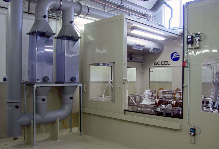
Hanspeter Vogel, CAS 08 – 17 June, 2010 DenmarkSurface Preparation of srf Cavities (1)
Surface preparation is used mainly for two purposes
1) Coarse treatment (100 to 150 µm of inner surface to remove the damage layer, which is
to be understood as the first (50 to 100 µm material layer affected by the manufacturing
process (forming, milling, grinding,…)
2) Final treatment: 20 to 40 µm preferably inside a clean room environment with
immediately following High Pressure Water Rinse (HPWR, 100 bar, some hours, ultrapure,
demineralized, particel filtered 0,01µm, class 10 , resp. ISO 4)
Three procedures for chemical surface preparation have been established
1) Buffered chemical polishing: HF (40%) / HNO3 (65%) / H3PO4 (85%) 1/1/2
(state of the art process)
2) Electropolishing: HF (48%) /H2SO4 (96%) 1/9 under application of voltage (17Volt) and a
current density about 350 A/m2 cavity surface (state of the art process)
3) Barrel-polishing (rarely applied)
Hanspeter Vogel, CAS 08 – 17 June, 2010 DenmarkSurface Preparation of srf Cavities (2)
Closed loop BCP
HPR
Assembly in clean room
Packing and shipping
for vertical test
Hanspeter Vogel, CAS 08 – 17 June, 2010 DenmarkSurface Preparation of srf Cavities (3) Electropolishing: a cavity is half filled with the electrolyte (HF (48%) /H2SO4 (96%)) with a cathode placed “on axis” and rotating while 17 Volt and a current density 0f 350 A/m² are applied. Hanspeter Vogel, CAS 08 – 17 June, 2010 Denmark
Cold rf testing of cavities (1)

    Cold rf testing of cavities is generally done with the
    individual cavity after surface preparation to show
    performance (cold frequency, quality factor, maximum
    achievable accelerating gradients)

    Test-installations are established in Research Institutes
    and used within the frame of cooperation agreements.
    Some installations are found in industry

                                     A XFEL Cavity (9 Cell, 1,3 GHz) under
                                            final rf control measurement
                                           completed with the cryogenic
                                            equipment ready to go into a
                                        cryostat for cold rf testing (2,0 K)

Hanspeter Vogel, CAS 08 – 17 June, 2010 Denmark
Cold rf testing of cavities (2)
typical preparation is done at
RI as follows:
• Degreasing
• Buffered chemical polishing
(1:1:2), in closed loop
chemistry, acid actively
cooled to temperatures
below 15 °C
Summary 500 MHz Single Cell Cavity Tests • Water Rising > 17 MOhmcm
1E+10 Cornell1
Cornell2 • High pressure water rinsing
SRRC1 (100 bar)
SRRC2 • Drying by pumping
• Assembly in class 100 clean
Qo
1E+09 CLS1
CLS2 room
DLS1
DLS2 • All test results achieved in
1E+08 DLS3 consecutive preparations /
0 1 2 3 4 tests
Vacc [MV] • All field values limited by
2 4 6 8 10 12 available RF power
Eacc [MV/m]
Hanspeter Vogel, CAS 08 – 17 June, 2010 DenmarkCold rf testing of cavities (3)
typical preparation is done at RI
• Degreasing
• Buffered chemical polishing
(1:1:2), in closed loop
chemistry, acid actively cooled
to temperatures below 15 °C
• Water Rising > 17 MOhmcm
• High pressure water rinsing
(100 bar)
• Drying by pumping
• Assembly in class 100 clean
room
Hanspeter Vogel, CAS 08 – 17 June, 2010 DenmarkAuxiliary components/Power couplers (1)
Besides other components
power couplers are the main
auxiliary component for a srf
module.
Power couplers:
• transfer the rf power from the
amplifier to the cavity
• provide the vacuum barrier to
the cavity
• provide the warm cold
transition (room temperature
to 2 or 4K)
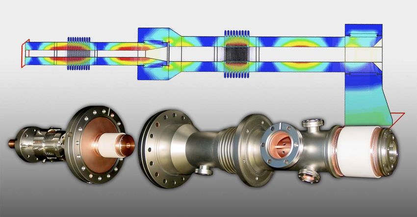
XFEL Power Coupler:
Power Couplers are of two main
Coaxial type with two ceramic windows (“cold designs:
and warm”) Coaxial or waveguide
Hanspeter Vogel, CAS 08 – 17 June, 2010 DenmarkAuxiliary components/Cryostat (1)
Main components of a srf module:
• cavity
• He-Vessel
• Heat shield (at intermediate temperature)
• Vacuum Vessel
• Power coupler
• Cryogenics supply
Artist view of a CORNELL srf module • Tuning system
500 Mhz, single cell • Vacuum system
Hanspeter Vogel, CAS 08 – 17 June, 2010 DenmarkAuxiliary components/Cryostat (2)
Vacuum vessel
with
preassembled
heat shield of a
500 MHz module
(CORNELL
desing)
Heat Shield with cryogenic piping
(LN2 cooling) and superinsulation
foil
Hanspeter Vogel, CAS 08 – 17 June, 2010 DenmarkAssembly of srf cavities
Steps
• completion of auxiliary
parts to the cavity (e.g.
power couple)
• connection of several
cavities and beam tubes
• quality control (rf-tests,
leak-tests)
leak testing of a XFEL string String assembly of 8 cavities for an XFEL module
Hanspeter Vogel, CAS 08 – 17 June, 2010 DenmarkAssembly of srf modules (1)
Completion of the XFEL
srf accelerator module
Hanspeter Vogel, CAS 08 – 17 June, 2010 DenmarkAssembly of srf modules (2)
Completion of a srf accelerator
module consisting out of 6 Half
Wave Resonators, 3 sc Solenoids,
and auxiliaries all assembled
below a “top-plate” (ready to be
moved into a vacuum vessel)
Hanspeter Vogel, CAS 08 – 17 June, 2010 DenmarkTransport of srf modules
Overseas transport by air freight
Land transport by truck with
the srf module mounted to a
special shock absorbing
transport frame
Hanspeter Vogel, CAS 08 – 17 June, 2010 DenmarkDelivery and Installation Hanspeter Vogel, CAS 08 – 17 June, 2010 Denmark
A 500 MHz Module to be placed at its final
 position in a storage ring

Hanspeter Vogel, CAS 08 – 17 June, 2010 Denmark
Technical Variants for SRF Cavity production:
 Nb on copper technology:
 LEP, LHC, Cornell, SOLEIL
                                                                                                                Assembly of
                                                                                                                the
                                                                                                                Niobium
                                                                                                                Cathode
                                                                                                                into a
                                                                                                                Copper
                                                                                                                cavity on
                                                                                                                the cavity
                                                                                                                axis

 10

                                                       srf cavities are produced by coating the inner surface of a copper
  1
                                                       cavity with a 1 to 2 µm niobium layer by magnetron sputtering.
                                  Tbath = 4.5 K
                                  Tbath = 2.5 K
                                                       By application of a magnetic field and a superposed electric dc
                                  SPEC                 field niobium is evaporated from the cathode and “condenses” on
0,1
      0   2   4    6    8    10     12    14      16   the copper surface.
Hanspeter Vogel, CAS 08 – 17 June, 2010 Denmark
Technical Variants for SRF Cavity production:
Nb on copper technology:
LEP, LHC, Cornell, SOLEIL
13 Meter Modules
for LEP housing 4
350 MHz cavities
produced by
sputtering Niobium
on Copper cavities
during final
assembly of the
modules
Hanspeter Vogel, CAS 08 – 17 June, 2010 DenmarkTechnical Variants for SRF Cavity production: Nb on copper technology: LEP, LHC, Cornell, SOLEIL 13 Meter Modules, turn key: Cavities, HOM-Couplers, Power Couplers, Tuners, Cryogenic Piping, assembly, low power tests, transport, guaranteed performance Hanspeter Vogel, CAS 08 – 17 June, 2010 Denmark
Acknowlegements

    I would like to thank all who have helped to prepare this presentation

    • Hiroaki Umezawa, Tokyo Denkai Co, Ltd

    • Axel Matheisen, Kay Jensch, DESY, Hamburg

    • Our colleagues at RI Research Instruments

    Thank you for
    your attention!

Hanspeter Vogel, CAS 08 – 17 June, 2010 Denmark
You can also read