Gas density monitor, model GDM-100 Gasdichtewächter, Typ GDM-100 - Gas density monitor with shut-off valve - Wika
←
→
Page content transcription
If your browser does not render page correctly, please read the page content below
Operating instructions
                                 Betriebsanleitung

Gas density monitor, model GDM-100                        EN

Gasdichtewächter, Typ GDM-100                             DE

          Gas density monitor with shut-off valve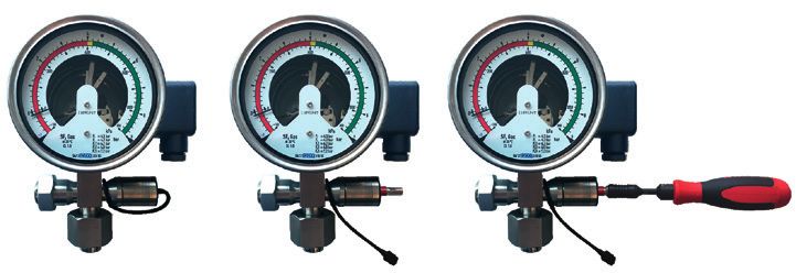
EN Operating instructions model GDM-100                            Page          3 - 24

DE Betriebsanleitung Typ GDM-100                                   Seite         25 - 47

   © 08/2018 WIKA Alexander Wiegand SE & Co. KG
   All rights reserved. / Alle Rechte vorbehalten.
   WIKA® is a registered trademark in various countries.
   WIKA® ist eine geschützte Marke in verschiedenen Ländern.
                                                                                                14300397.01 08/2018 EN/DE

   Prior to starting any work, read the operating instructions!
   Keep for later use!

   Vor Beginn aller Arbeiten Betriebsanleitung lesen!
   Zum späteren Gebrauch aufbewahren!

    2                           WIKA operating instructions gas density monitor model GDM-100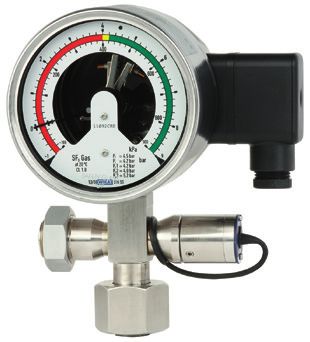
Contents

                            Contents
                            1. General information                                           4   EN
                            2. Design and function                                           5
                            3. Safety		                                                      6
                            4. Transport, packaging and storage                             11
                            5. Commissioning, operation                                     12
                            6. Faults		                                                     17
                            7. Maintenance, cleaning and recalibration                      18
                            8. Dismounting, return and disposal                             20
                            9. Specifications                                               21
                            10. Accessories                                                 23
14300397.01 08/2018 EN/DE

                            WIKA operating instructions gas density monitor model GDM-100    3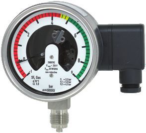
1. General information

     1. General information
     ■■ The instrument described in the operating instructions has been designed and
          manufactured using state-of-the-art technology. All components are subject to strin-
EN        gent quality and environmental criteria during production. Our management systems
          are certified to ISO 9001 and ISO 14001.

     ■■ These operating instructions contain important information on handling the instru-
          ment. Working safely requires that all safety instructions and work instructions are
          observed.

     ■■ Observe the relevant local accident prevention regulations and general safety regula-
          tions for the instrument’s range of use.

     ■■ The operating instructions are part of the product and must be kept in the immediate
          vicinity of the instrument and readily accessible to skilled personnel at any time. Pass
          the operating instructions on to the next operator or owner of the instrument.

     ■■ Skilled personnel must have carefully read and understood the operating instructions
          prior to beginning any work.

     ■■ The general terms and conditions contained in the sales documentation shall apply.

     ■■ Subject to technical modifications.

     ■■ Further information:
          - Internet address:         www.wika.de / www.wika.com
          - Relevant data sheets:
                           AC 20.01      Model GDM-100 with test connection and shut-off valve
                           SP 60.02      Model GDM-100
          - Application consultant:      Tel.: +49 9372 132-0
                                         Fax: +49 9372 132-406
                                         info@wika.com
                                                                                                     14300397.01 08/2018 EN/DE

      4                             WIKA operating instructions gas density monitor model GDM-100
2. Design and function
2. Design and function
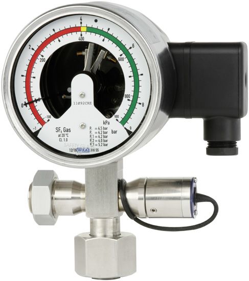
2.1 Overview
Gas density monitor Gas density monitor with test connection and EN
shut-off valve
Product label Product label
Electrical connection, cable socket Electrical connection, cable socket
Process connection, spanner flats Shut-off valve
Process connection, thread Plug for valve setting
Process connection, spanner flats (gas
compartment)
Test connection, spanner flats (calibration
pressure)
2.2 Description
Switch contacts
The switch contacts permanently installed in the gas density monitor close or open at
set limit values, depending on the switching function. Switching functions are: Normally
closed, normally open, change-over contact.
The magnetic snap-action contacts are auxiliary current switches which open or close
connected electric circuits via a contact arm which is moved by the instrument pointer.
14300397.01 08/2018 EN/DE
WIKA operating instructions gas density monitor model GDM-100 52. Design and function / 3. Safety
Shut-off valve with safety function
For recalibration, the gas density monitor can be isolated from the gas compartment via
the shut-off valve without having to dismount it. The shut-off valve can only be operated
with the socket wrench delivered with it.
EN For safety reasons, the socket wrench cannot be removed from the socket wrench
socket if the gas density monitor is isolated from the gas compartment. This prevents
the shut-off valve from inadvertently not being opened after recalibration and the gas
chamber from not being monitored as a result.
2.3 Scope of delivery
Cross-check scope of delivery with delivery note.
3. Safety
3.1 Explanation of symbols
WARNING!
... indicates a potentially dangerous situation that can result in serious
injury or death, if not avoided.
CAUTION!
... indicates a potentially dangerous situation that can result in light injuries
or damage to property or the environment, if not avoided.
Information
... points out useful tips, recommendations and information for efficient
and trouble-free operation.
3.2 Intended use
Wherever the gas density of SF₆ gas has to be indicated locally and, at the same time,
circuits need to be switched, the model GDM-100 gas density monitor finds its use.
Gas density monitors are modified contact pressure gauges, specially developed for the
use of SF₆ gas. Temperature influences acting on the enclosed SF₆ gas are compensa-
ted by a compensation system.
The gas density monitors are specially designed for the respective application in switch-
gear (pure SF₆ gas, gas mixtures, calibration pressure, switch points ...). Before use,
14300397.01 08/2018 EN/DE
check whether this instrument is suitable for the intended application.
6 WIKA operating instructions gas density monitor model GDM-1003. Safety
The insulation values (air gaps and creepage distances) are sized for the following
ambient conditions in accordance with EN 61010-1:2010:
■■ Altitude up to 2,000 m
■■ Overvoltage category II
■■ Pollution degree 2 EN
■■ Relative humidity: 0 ... 95 % non-condensing (per DIN 40040)
■■ The strength of the measuring instrument (enclosing non-metal components)
was tested with a reduced impact energy of 2 J corresponding to IK07 per
EN 61010-1:2010. The IK code is included on the respective product label.
Only use the instrument in applications that lie within its technical performance limits
(e.g. max. ambient temperature, material compatibility, ...).
→ For performance limits see chapter 9 “Specifications”.
This instrument is not permitted to be used in hazardous areas!
The instrument has been designed and built solely for the intended use described here,
and may only be used accordingly.
The technical specifications contained in these operating instructions must be obser-
ved. Improper handling or operation of the instrument outside of its technical specifica-
tions requires the instrument to be taken out of service immediately and inspected by an
authorised WIKA service engineer.
The manufacturer shall not be liable for claims of any type based on operation contrary
to the intended use.
3.3 Improper use
WARNING!
Injuries through improper use
Improper use of the instrument can lead to hazardous situations and
injuries.
▶▶ Refrain from unauthorised modifications to the instrument.
▶▶ Do not use the instrument within hazardous areas.
Any use beyond or different to the intended use is considered as improper use.
14300397.01 08/2018 EN/DE
WIKA operating instructions gas density monitor model GDM-100 73. Safety
3.4 Responsibility of the operator
The instrument is used in the industrial sector. The operator is therefore responsible for
legal obligations regarding safety at work.
EN The safety instructions within these operating instructions, as well as the safety,
accident prevention and environmental protection regulations for the application area
must be maintained.
The operator is obliged to maintain the product label in a legible condition.
To ensure safe working on the instrument, the operating company must ensure
■■ that suitable first-aid equipment is available and aid is provided whenever required.
■■ that the operating personnel are regularly instructed in all topics regarding work
safety, first aid and environmental protection and know the operating instructions and
in particular, the safety instructions contained therein.
■■ that the instrument is suitable for the particular application in accordance with its
intended use.
■■ that personal protective equipment is available.
3.5 Personnel qualification
WARNING!
Risk of injury should qualification be insufficient
Improper handling can result in considerable injury and damage to equip-
ment.
▶▶ The activities described in these operating instructions may only be
carried out by skilled personnel who have the qualifications described
below.
Skilled personnel
Skilled personnel, authorised by the operator, are understood to be personnel who,
based on their technical training, knowledge of measurement and control technolo-
gy and on their experience and knowledge of country-specific regulations, current
standards and directives, are capable of carrying out the work described and indepen-
dently recognising potential hazards.
Specifically when using SF₆ gas
The plant operator must ensure that the handling of SF6 gas is only carried out by
a qualified company or by qualified persons who have been specially trained in
accordance with IEC 61634, section 4.3.1 or IEC 60480, section 10.3.1.
14300397.01 08/2018 EN/DE
8 WIKA operating instructions gas density monitor model GDM-1003. Safety
3.6 Personal protective equipment
The personal protective equipment is designed to protect the skilled personnel from
hazards that could impair their safety or health during work. When carrying out the
various tasks on and with the instrument, the skilled personnel must wear personal
protective equipment. EN
Follow the instructions displayed in the work area regarding personal protective
equipment!
The requisite personal protective equipment must be provided by the operating company.
Safety goggles in accordance with EN 166, class 2, mechanical
strength class S
The safety goggles must be worn over the entire period when working on
hoses or gas containers (e.g. gas cylinders, tanks).
The safety goggles protect the eyes from any flying particles, escaping
gas and liquid splashes.
Protective gloves against heat in accordance with EN ISO 13732-1
and against cold in accordance with EN ISO 13732-3
The protective gloves must be worn over the entire period when working
on hoses, gas containers (e.g. gas cylinders, tanks) or components which
heat up to over 60 °C.
3.7 Handling of insulating gases and gas mixtures
SF₆ gas is a greenhouse gas which is listed in the Kyoto Protocol. SF₆ gas must not be
released into the atmosphere, but must be collected in suitable containers.
Properties of insulating gases
■■Colourless and odourless
■■Chemically neutral
■■Inert
■■Not flammable
■■Heavier than air
■■No toxicity
■■No damage to the ozone layer
Detailed information is given in IEC 60376 and IEC 61634.
14300397.01 08/2018 EN/DE
WIKA operating instructions gas density monitor model GDM-100 93. Safety
Danger of suffocation caused by insulating gases and gas mixtures
High concentrations of gases can lead to asphyxiation, since breathable air is displaced
from the lungs with the inhalation of gas.
Since SF₆ gas is heavier than air, it collects, especially, at ground level or lower-lying
EN rooms below the reference level (e.g. cellars). This is particularly dangerous since SF₆
gas is colourless and odourless and thus may be imperceptible to people.
3.8 Danger caused by decomposition products
Insulating gas in electrical systems may contain decomposition products generated by
electric arcs:
■■ Gaseous sulphur fluoride
■■ Sulphur hexafluoride
■■ Solid and atomized metal fluorides, metal sulfides, metal oxides
■■ Hydrogen fluoride
■■ Sulphur dioxide
Decomposition products can be harmful to health.
■■ They can cause poisoning by inhalation, ingestion or contact with the skin.
■■ They may be irritating to the eyes, the respiratory system or the skin and burn them.
■■ Inhalation of large quantities may damage the lungs.
Observe the following safety instructions in order to avoid danger from insulating gas:
■■ Wear personal protective equipment.
■■ Read the material safety data sheet of the gas supplier.
■■ With large leaks, evacuate the area quickly.
■■ Ensure good ventilation.
■■ Ensure the leak tightness of the equipment with a leak detector (e.g. model GIR-10).
3.9 Applicable standards and directives, installation, assembly, commissioning:
■■ BGI 753 (SF₆ plants and equipment in Germany)
■■ IEC 61634 (Handling of SF₆ gas)
■■ IEC 60376 (New SF₆ gas, technical grade SF₆ gas)
■■ IEC 60480 (Used SF₆ gas)
■■ CIGRE report 276, 2005 (Practial SF₆ gas handling instructions)
Leaks during operation:
■■ IEC 60376 (New SF₆ gas, technical grade SF₆ gas)
■■ IEC 60480 (Used SF₆ gas)
■■ CIGRE 2002 (“SF₆ gas in the electrical industry”)
SF6 is a colourless and odourless, chemically neutral, inert and
14300397.01 08/2018 EN/DE
non-flammable gas which is approx. five times heavier than air, non-toxic
and not harmful to the ozone layer.
Detailed information is given in IEC 60376 and IEC 61634.
10 WIKA operating instructions gas density monitor model GDM-1003. Safety / 4. Transport, packaging and storage
3.10 Labelling, safety marks
Product label (example)
Dichtewächter mit Kontakeinrichtung EN
Density monitor with alarm contacts
Schaltzustand bei Skalenanfangswert / Status of switch at minimum scale value Made in Germay
Model designation
Pin assignment
Case filling
P# Product No.
Date of manufacture
Switching thresholds
Electrical characteristics
Model designation of the switch contact
4. Transport, packaging and storage
4.1 Transport
Check the instrument for any damage that may have been caused by transport.
Obvious damage must be reported immediately.
CAUTION!
Damage through improper transport
With improper transport, a high level of damage to property can occur.
▶▶ When unloading packed goods upon delivery as well as during inter-
nal transport, proceed carefully and observe the symbols on the
packaging.
▶▶ With internal transport, observe the instructions in chapter 4.2
14300397.01 08/2018 EN/DE
“Packaging and storage”.
WIKA operating instructions gas density monitor model GDM-100 114. Transport, ... / 5. Commissioning, operation
4.2 Packaging and storage
Do not remove packaging until just before mounting.
Keep the packaging as it will provide optimum protection during transport (e.g. change
in installation site, sending for repair).
EN
WARNING!
Physical injuries and damage to property and the environment
caused by hazardous decomposition products
Before storing the instrument, any residual decomposition products must
be removed.
▶▶ For cleaning, see chapter 7.2 “Cleaning”
Permissible conditions at the place of storage:
■■ Storage temperature: -50 ... +60 °C
■■ Humidity: ≤ 90 % r. h. (non-condensing)
Avoid exposure to the following factors:
■■ Direct sunlight or proximity to hot objects
■■ Mechanical vibration, mechanical shock (putting it down hard)
■■ Soot, vapour, dust and corrosive gases
■■ Hazardous environments, flammable atmospheres
Store the instrument in its original packaging in a location that fulfils the conditions
listed above. If the original packaging is not available, pack and store the instrument as
described below:
1. Place the instrument, along with the shock-absorbent material, in the packaging.
2. If stored for a prolonged period of time (more than 30 days), place a bag containing
a desiccant inside the packaging.
5. Commissioning, operation
5.1 Mechanical mounting
CAUTION!
Physical injuries and damage to property and the environment
through faulty instrument
Prior to commissioning, the instrument must be subjected to a visual
inspection. Only use the instrument if it is in perfect condition with respect
to safety.
14300397.01 08/2018 EN/DE
5.1.1 Requirements for the installation point
■■ For outdoor applications, the selected installation location has to be suitable for the
specified ingress protection, so that the instrument is not exposed to impermissible
weather conditions.
■■ The sealing faces at the instrument have to be undamaged and clean.
12 WIKA operating instructions gas density monitor model GDM-1005. Commissioning, operation
5.1.2 Installation
■■ With transport or storage, it can occur that gas density monitors warm up or cool
down and this results in pointer movements. These pointer movements are caused by
the compensation system. To make sure that the instruments have adapted sufficient-
ly to ambient temperature, at least 2 hours at 20 °C must be allowed for adaptation EN
to the temperature. Then, in the depressurised state, the pointer will sit within the
tolerance bar.
■■ Corresponding to the general technical rules for pressure gauges (e.g. EN 837-2
“Selection and installation recommendations for pressure gauges”) when screwing in
the instrument, the force required to do this must not be applied through the case, but
only through the spanner flats provided for this purpose and using a suitable tool.
■■ When screwing in, do not cross the threads.
For parallel threads, use flat gaskets, lens-type sealing rings or WIKA profile sealings
at the sealing face . With tapered threads (e.g. NPT threads), sealing is made in the
threads , using a suitable sealing material (EN 837-2).
The tightening torque depends on the sealing used. In order to orientate the measuring
instrument so that it can be read as well as possible, a connection with LH-RH union or
union nut should be used. When a blow-out device is fitted to an instrument, it must be
protected against being blocked by debris and dirt.
Spanner flats
Sealing in the thread
Sealing face
5.1.3 Temperature load
The installation of the instrument should be made in such a way that the operating
temperature, also considering the effects of convection and thermal radiation, neither
exceeds nor falls below the permissible limits. The influence of temperature on the
indication and measurement accuracy must be observed.
5.2 Electrical mounting
■■ The instrument must be grounded via the process connection.
■■ For cable outlets, make sure that no moisture enters at the cable end.
■■ Select a cable diameter that matches the cable bushing of the connector. Make sure
that the cable gland of the mounted connector has a tight fit and that the sealings are
present and undamaged. Tighten the threaded connection and check that the sealing
is correctly seated, in order to ensure the ingress protection.
14300397.01 08/2018 EN/DE
■■ Connection details and switching functions are given on the product label. Connec-
tion terminals and ground terminal are appropriately marked.
WIKA operating instructions gas density monitor model GDM-100 135. Commissioning, operation
5.2.1 Limit values for the contact load with resistive load
gas-filled instruments liquid-filled instruments
Maximum rated operating AC 250 V AC 250 V
EN voltage Ueff
Rated operating current
Switch-on current 1A 1A
Switch-off current 1A 1A
Continuous current 0.6 A 0.6 A
Maximum switching power 30 W, 50 VA 20 W, 20 VA
Do not exceed the limit values. In order to ensure permanent safe functioning, the
following load values are recommended:
Voltage gas-filled instruments liquid-filled instruments
(per IEC 38)
resistive load inductive resistive load inductive load
load
DC/AC DC AC cos ϕ >0.7 DC AC cos ϕ >0.7
230 V 100 mA 120 mA 65 mA 65 mA 90 mA 40 mA
110 V 200 mA 240 mA 130 mA 130 mA 180 mA 85 mA
48 V 300 mA 450 mA 200 mA 190 mA 330 mA 130 mA
24 V 400 mA 600 mA 250 mA 250 mA 450 mA 150 mA
The switching current must not be less than 20 mA with low voltages for switching relia-
bility reasons.
For higher loads, and for instruments with liquid-filled cases, WIKA model
905.1X contact protection relays are recommended.
Overcurrent protectors
The instruments do not provide for incorporated overcurrent protectors. Should protec-
tors be required, the following values in accordance with EN 60 947-5-1 are to be
recommended.
■■ Voltage 24 V: 2 A
14300397.01 08/2018 EN/DE
■■ Voltage 250 V: 1 A
14 WIKA operating instructions gas density monitor model GDM-1005. Commissioning, operation
5.2.2 Contact protection measures
Mechanical contacts must not exceed the specified electrical values for switching
current, switching voltage and switching power independent of each other, not even for
a short time only.
For capacitive or inductive loads we recommend one of the following protective circuits: EN
Inductive load with DC voltage
With DC voltage the contact protection can be achieved via a free-wheeling diode,
connected in parallel to the load. The polarity of the diode must be arranged so that it
closes when the operating voltage is on.
Example: Contact
protection measure Contact
with free-wheeling
diode
Diode Load
Inductive load with AC voltage
With AC voltage two protection measures are possible:
Example: Contact
protection measure
with voltage-de-
pendent resistor
VDR
Load
Example: Contact
protection measure
with RC element
Load
14300397.01 08/2018 EN/DE
WIKA operating instructions gas density monitor model GDM-100 155. Commissioning, operation
Capacitive load
With capacitive loads elevated switch-on currents arise. These can be reduced by
series-connecting resistors in the supply line.
EN Examples: Contact protection measure with current-limiting resistor
UB UB
R1 R1
Load Load
5.3 Switch point setting
The switch points have a fixed setting as standard and cannot be adjusted. Thus, an
undesired adjustment of the switch points is excluded.
With customer-specific, adjustable switch points, with the accompanying adjustment
key, the desired set point can be set via the adjustment lock in the window.
14300397.01 08/2018 EN/DE
16 WIKA operating instructions gas density monitor model GDM-1006. Faults
6. Faults
CAUTION!
Physical injuries and damage to property and the environment
If faults cannot be eliminated by means of the listed measures, the instru- EN
ment must be taken out of operation immediately.
▶▶ Ensure that pressure or signal is no longer present and protect against
accidental commissioning.
▶▶ Contact the manufacturer.
▶▶ If a return is needed, please follow the instructions given in chapter 9.2
“Return”.
For contact details see chapter 1 “General information” or the back page
of the operating instructions.
Faults Causes Measures
Contact is no longer Electrical connection is inter- Carry out a continuity test on
switching in line with the rupted. the electrical connection lines.
specification.
Electrical load unsuitable for Maintain the permissible
the switch contact model. electrical loads for the switch
contact model.
Contact contaminated.
Switching status remains Contacts defective (e.g. fused Replace instrument Before
unchanged despite contact zone). recommissioning the new
reaching the switch point/ instrument, provide a protecti-
reset point. ve circuit for the contact.
No pointer movement Movement blocked. Replace instrument
despite change in pressure.
Pointer movement, even Warming or cooling of the Let the instrument settle for 2
though depressurised. measuring instrument (no hours at 20 °C.
damage)
For claims, the serial and product numbers must be stated. The serial number is printed
on the dial, the product number on the product label. With claims, the atmospheric
pressure and the temperature during the measurement must be given, as well as the
data on the reference standard (model, class).
14300397.01 08/2018 EN/DE
WIKA operating instructions gas density monitor model GDM-100 177. Maintenance, cleaning and recalibration
7. Maintenance, cleaning and recalibration
7.1 Maintenance
These gas density monitors are maintenance-free.
EN The indication and switching function should be checked once or twice every year. For
this the instrument must be disconnected from the gas compartment to check with a
pressure testing device.
Repairs must only be carried out by the manufacturer.
The instruments must not be opened, since this can lead to indication and switch point
errors.
7.2 Cleaning
CAUTION!
Physical injuries and damage to property and the environment
Improper cleaning may lead to physical injuries and damage to property
and the environment. Decomposition products in the dismounted instru-
ment can result in a risk to persons, the environment and equipment.
▶▶ Carry out the cleaning process as described below.
1. Before cleaning, correctly disconnect the instrument from the pressure supply and
switch off the current.
2. Use the requisite protective equipment.
3. Clean the instrument with a moist cloth.
Electrical connections must not come into contact with moisture!
CAUTION!
Damage to the instrument
Improper cleaning may lead to damage to the instrument!
▶▶ Do not use any aggressive cleaning agents.
▶▶ Do not use any hard or pointed objects for cleaning.
4. Wash or clean the dismounted instrument, in order to protect people and the environ-
ment from exposure to residual decomposition products.
Information on returns can be found under the heading “Service” on our
local website.
14300397.01 08/2018 EN/DE
18 WIKA operating instructions gas density monitor model GDM-1007. Maintenance, cleaning and recalibration
7.3 Calibration
The gas density monitor can be calibrated via a special calibration system for gas density
measuring instruments (e.g. WIKA BCS-10).
The gas density monitor with test connection and shut-off valve can be isolated from the
gas compartment using the shut-off valve, without the gas density monitor needing to be EN
dismounted. With gas density monitors that do not offer a test connection and shut-off
valve, the gas density monitor must be dismounted professionally. In this case, it may be
necessary to take the entire system temporarily out of service.
Calibration of the gas density monitor with test connection and shut-off valve
CAUTION!
Discontinuity in the monitoring function
During calibration, the gas density monitor must be isolated from the gas
compartment being monitored. In the event of a leakage, no alarm will be
able to be given.
▶▶ After calibration, open the shut-off valve again.
Shut-off valve tightening torque: 1.2 Nm ±10 %
Test connection tightening torque: 60 Nm ±10 %
1 2 3
1. Pull out the plug for valve setting (1).
2. Insert the socket wrench insert into the valve setting (2).
3. Turn the valve setting to the “CLOSE” position (3) with the aid of the socket wrench.
■■ Socket wrench insert can no longer be pulled out.
■■ Gas density monitor is isolated from the gas compartment.
4. Connect the test gas and test standard with the test connection.
14300397.01 08/2018 EN/DE
5. Make the calibration.
6. Turn the valve setting to the “OPEN” position (3) with the aid of the socket wrench.
■■ Socket wrench insert can now be pulled out again.
■■ Gas density monitor is connected to the gas compartment.
7. Isolate the test gas and test standard from the test connection.
WIKA operating instructions gas density monitor model GDM-100 198. Dismounting, return and disposal
8. Dismounting, return and disposal
8.1 Dismounting
EN WARNING!
Physical injuries and damage to property and the environment
caused by hazardous decomposition products
Upon contact with hazardous decomposition products, there is a danger
of physical injuries and damage to property and the environment.
▶▶ Wear the requisite protective equipment (see chapter 3.6 “Personal
protective equipment”).
Before dismantling the instrument, evacuate the gas filling.
Only dismount the instrument when it is depressurised and free from current.
8.2 Return
WARNING!
Strictly observe the following when shipping the instrument:
All instruments delivered to WIKA must be free from any kind of hazar-
dous substances (e.g. decomposition products) and must therefore be
cleaned before being returned.
When returning the instrument, use the original packaging or a suitable transport
packaging.
To avoid damage:
1. Place the instrument, along with the shock-absorbent material, in the packaging.
Place shock-absorbent material evenly on all sides of the transport packaging.
2. If possible, place a bag containing a desiccant inside the packaging.
Information on returns can be found under the heading “Service” on our
local website.
8.3 Disposal
Incorrect disposal can put the environment at risk.
Dispose of instrument components and packaging materials in an environmentally
compatible way and in accordance with the country-specific waste disposal regulations.
14300397.01 08/2018 EN/DE
20 WIKA operating instructions gas density monitor model GDM-1009. Specifications
9. Specifications
Specifications
Nominal size 100 EN
Calibration pressure PE To customer specification
Accuracy specifications ±1 % at an ambient temperature of +20 °C
±2.5 % at ambient temperature -20 … +60 °C
and with calibration pressure in accordance with
reference isochore (reference diagram KALI-Chemie
AG, Hanover, prepared by Dr. Döring 1979)
Scale range Vacuum and overpressure range with measuring
span of 1.6 ... 25 bar (at an ambient temperature of
20 °C and gaseous phase)
Permissible ambient temperature
Operation -20 ... +60 °C (-4 ... +140 °F), gaseous phase
Storage -50 ... +60 °C (-58 ... +140 °F)
Process connection G ½ B per EN 837, lower mount
Stainless steel, spanner flats 22 mm
Pressure element Stainless steel, welded
Gas-tight: Leak rate ≤ 1 · 10-8 mbar · l / s
Test method: Helium mass spectrometry
Movement Stainless steel
Bimetal link (temperature compensation)
Dial Aluminium
The scale range is subdivided into red, yellow and
green ranges
Pointer Aluminium, black
Case Stainless steel
Gas-tight: Leak rate ≤ 1 · 10-5 mbar · l / s
Window Laminated safety glass or clear non-splintering
plastic
Ring Bayonet ring, stainless steel, secured by means of 3
welding spots
Permissible air humidity ≤ 90 % r. h. (non-condensing)
Ingress protection IP65 per IEC/EN 60529
14300397.01 08/2018 EN/DE
Weight With gas filling: approx. 0.8 kg
With filling liquid: approx. 1.2 kg
High-voltage test 100 % 2 kV, 50 Hz, 1s
Electrical connection Cable socket with compression fitting M20 x 1.5
Wire cross-section max. 2.5 mm²
WIKA operating instructions gas density monitor model GDM-100 219. Dismounting, return and disposal
Specifications
Number of switch contacts 1 ... 3 magnetic snap-action contacts
Switching directions Falling pressure or rising pressure
EN Switching functions Normally open, normally closed or change-over
contact
Circuits Galvanically connected (not for change-over
contact) or galvanically isolated
Switching accuracy
Switch point = calibration pressure PE: see accuracy specifications
Switch point ≠ calibration pressure PE: Parallel to the reference isochore of the calibration
pressure
Max. switching voltage AC 250 V
Switching power With gas filling: 30 W / 50 VA, max. 1 A
With filling liquid: 20 W / 20 VA, max. 1 A
Material of switch contacts 80 % Ag / 20 % Ni, gold-plated
For further specifications, see the order documentation.
Dimensions in mm
14300397.01 08/2018 EN/DE
22 WIKA operating instructions gas density monitor model GDM-1009. Dismounting, return and disposal / 10. Accessories
EN
10. Accessories
Description Order
number
Adapter from test connection (M26 x 1.5) to RECTUS quick 14146937
coupling
Tool set for working the shut-off valve 14232498
Wrench socket for shut-off valve (SQ 5.2 mm 1/) 14146708
Protection cap for test connection (M26 x 1.5) 14193772
14300397.01 08/2018 EN/DE
Protection cap for shut-off valve (silicone) 14183253
WIKA accessories can be found online at www.wika.com.
WIKA operating instructions gas density monitor model GDM-100 23EN
14300397.01 08/2018 EN/DE
24 WIKA operating instructions gas density monitor model GDM-100Inhalt
Inhalt
1. Allgemeines 26
2. Aufbau und Funktion 27
3. Sicherheit 28
DE
4. Transport, Verpackung und Lagerung 33
5. Inbetriebnahme, Betrieb 34
6. Störungen 39
7. Wartung, Reinigung and Rekalibrierung 40
8. Demontage, Rücksendung und Entsorgung 42
9. Technische Daten 43
10. Zubehör 45
14300397.01 08/2018 EN/DE
WIKA Betriebsanleitung Gasdichtewächter Typ GDM-100 251. Allgemeines
1. Allgemeines
■■ Das in der Betriebsanleitung beschriebene Gerät wird nach dem aktuellen Stand der
Technik konstruiert und gefertigt. Alle Komponenten unterliegen während der Ferti-
gung strengen Qualitäts- und Umweltkriterien. Unsere Managementsysteme sind
nach ISO 9001 und ISO 14001 zertifiziert.
DE
■■ Diese Betriebsanleitung gibt wichtige Hinweise zum Umgang mit dem Gerät.
Voraussetzung für sicheres Arbeiten ist die Einhaltung aller angegebenen
Sicherheitshinweise und Handlungsanweisungen.
■■ Die für den Einsatzbereich des Gerätes geltenden örtlichen
Unfallverhütungsvorschriften und allgemeinen Sicherheitsbestimmungen einhalten.
■■ Die Betriebsanleitung ist Produktbestandteil und muss in unmittelbarer Nähe des
Gerätes für das Fachpersonal jederzeit zugänglich aufbewahrt werden. Betriebsan-
leitung an nachfolgende Benutzer oder Besitzer des Gerätes weitergeben.
■■ Das Fachpersonal muss die Betriebsanleitung vor Beginn aller Arbeiten sorgfältig
durchgelesen und verstanden haben.
■■ Es gelten die allgemeinen Geschäftsbedingungen in den Verkaufsunterlagen.
■■ Technische Änderungen vorbehalten.
■■ Weitere Informationen:
- Internet-Adresse: www.wika.de / www.wika.com
- zugehörige Datenblätter:
AC 20.01 Typ GDM-100 mit Prüfanschluss und Absperrventil
SP 60.02 Typ GDM-100
- Anwendungsberater: Tel.: +49 9372 132-0
Fax: +49 9372 132-406
info@wika.de
14300397.01 08/2018 EN/DE
26 WIKA Betriebsanleitung Gasdichtewächter Typ GDM-1002. Aufbau und Funktion
2. Aufbau und Funktion
2.1 Überblick
Gasdichtewächter Gasdichtewächter mit Prüfanschluss und
Absperrventil
DE
Typenschild Typenschild
Elektrische Anschluss, Kabeldose Elektrische Anschluss, Kabeldose
Prozessanschluss, Schlüsselfläche Absperrventil
Prozessanschluss, Gewinde Stopfen für Ventileinstellung
Prozessanschluss, Schlüsselfläche
(Gasraum)
Prüfanschluss, Schlüsselfläche
(Kalibrierdruck)
2.2 Beschreibung
Schaltkontakte
Die im Gasdichtewächter fest eingebauten Schaltkontakte schließen oder öffnen bei
eingestellten Grenzwerten je nach Schaltfunktion. Schaltfunktionen sind: Öffner, Schlie-
ßer, Wechsler.
Die Magnetspringkontakte sind Hilfsstromschalter, die angeschlossene elektrische
Stromkreise über einen vom Gerätezeiger bewegten Kontaktarm öffnen oder schließen.
14300397.01 08/2018 EN/DE
WIKA Betriebsanleitung Gasdichtewächter Typ GDM-100 272. Aufbau und Funktion / 3. Sicherheit
Absperrventil mit Sicherheitsfunktion
Zur Rekalibirerung kann der Gasdichtwächter über das Absperrventil vom Gasraum
getrennt werden ohne ihn demontieren zu müssen. Das Absperrventil lässt sich
ausschließlich mit dem mitgelieferten Steckschlüssel betätigen.
Aus Sicherheitsgründen kann der Steckschlüssel nicht aus dem Steckschlüsselein-
satz abegzogen werden, wenn der Gasdichtewächter vom Gasraum getrennt ist. Dies
verhindert, dass nach einer Rekalibrierung das Absperrventil versehentlich nicht mehr
DE geöffnet wird und der Gasraum dadurch nicht überwacht wird.
2.3 Lieferumfang
Lieferumfang mit dem Lieferschein abgleichen.
3. Sicherheit
3.1 Symbolerklärung
WARNUNG!
... weist auf eine möglicherweise gefährliche Situation hin, die zum Tod
oder zu schweren Verletzungen führen kann, wenn sie nicht gemieden
wird.
VORSICHT!
... weist auf eine möglicherweise gefährliche Situation hin, die zu geringfü-
gigen oder leichten Verletzungen bzw. Sach- und Umweltschäden führen
kann, wenn sie nicht gemieden wird.
Information
... hebt nützliche Tipps und Empfehlungen sowie Informationen für einen
effizienten und störungsfreien Betrieb hervor.
3.2 Bestimmungsgemäße Verwendung
Überall dort, wo die Gasdichte von SF₆-Gas vor Ort angezeigt werden muss und gleich-
zeitig Stromkreise geschaltet werden sollen, findet der Gasdichtewächter Typ GDM-100
seinen Einsatz.
Gasdichtewächter sind abgewandelte Kontaktmanometer, die speziell für die Verwen-
dung von SF₆-Gas entwickelt wurden. Temperatureinflüsse die auf das eingeschlossene
SF₆-Gas wirken, werden durch ein Kompensationssystem ausgeglichen.
Die Gasdichtewächter sind speziell für den jeweiligen Einsatzfall in der Schaltanlage
14300397.01 08/2018 EN/DE
ausgelegt (reines SF₆-Gas, Gasgemische, Eichdruck, Schaltpunkte…). Vor der Verwen-
dung überprüfen, ob das vorliegende Gerät für den vorgesehenen Einsatzfall geeignet
ist.
28 WIKA Betriebsanleitung Gasdichtewächter Typ GDM-1003. Sicherheit
Die Isolationswerte (Luft -und Kriechstrecken) sind gemäß EN 61010-1:2010 für folgende
Umgebungsbedingungen bemessen:
■■ Höhenlage bis 2.000 m
■■ Überspannungskategorie II
■■ Verschmutzungsgrad 2
■■ Relative Feuchte: 0 ... 95 % nicht betauend (nach DIN 40040)
■■ Die Festigkeit des Messgerätes (umhüllende, nicht metallische Bauteile) ist mit einer
verringerten Schlagenergie von 2 J entsprechend IK07 gemäß EN 61010-1:2010
DE
getestet worden. Der IK-Code ist dem jeweiligen Typenschild zu entnehmen.
Das Gerät nur in Anwendungen verwenden, die innerhalb seiner technischen Leistungs-
grenzen liegen (z. B. max. Umgebungstemperatur, Materialverträglichkeit, ...).
→ Leistungsgrenzen siehe Kapitel 9 „Technische Daten“.
Dieses Gerät ist nicht für den Einsatz in explosionsgefährdeten Bereichen zugelassen!
Das Gerät ist ausschließlich für den hier beschriebenen bestimmungsgemäßen
Verwendungszweck konzipiert und konstruiert und darf nur dementsprechend verwen-
det werden.
Die technischen Spezifikationen in dieser Betriebsanleitung sind einzuhalten. Eine
unsachgemäße Handhabung oder ein Betreiben des Gerätes außerhalb der techni-
schen Spezifikationen macht die sofortige Stilllegung und Überprüfung durch einen
autorisierten WIKA-Servicemitarbeiter erforderlich.
Ansprüche jeglicher Art aufgrund von nicht bestimmungsgemäßer Verwendung sind
ausgeschlossen.
3.3 Fehlgebrauch
WARNUNG!
Verletzungen durch Fehlgebrauch
Fehlgebrauch des Gerätes kann zu gefährlichen Situationen und Verlet-
zungen führen.
▶▶ Eigenmächtige Umbauten am Gerät unterlassen.
▶▶ Gerät nicht in explosionsgefährdeten Bereichen einsetzen.
Jede über die bestimmungsgemäße Verwendung hinausgehende oder andersartige
Benutzung gilt als Fehlgebrauch.
14300397.01 08/2018 EN/DE
WIKA Betriebsanleitung Gasdichtewächter Typ GDM-100 293. Sicherheit
3.4 Verantwortung des Betreibers
Das Gerät wird im gewerblichen Bereich eingesetzt. Der Betreiber unterliegt daher den
gesetzlichen Pflichten zur Arbeitssicherheit.
Die Sicherheitshinweise dieser Betriebsanleitung, sowie die für den Einsatzbereich des
Gerätes gültigen Sicherheits-, Unfallverhütungs- und Umweltschutzvorschriften einhalten.
DE Der Betreiber ist verpflichtet das Typenschild lesbar zu halten.
Für ein sicheres Arbeiten am Gerät muss der Betreiber sicherstellen,
■■ dass eine entsprechende Erste-Hilfe-Ausrüstung vorhanden ist und bei Bedarf jeder-
zeit Hilfe zur Stelle ist.
■■ dass das Bedienpersonal regelmäßig in allen zutreffenden Fragen von Arbeitssicher-
heit, Erste Hilfe und Umweltschutz unterwiesen wird, sowie die Betriebsanleitung
und insbesondere die darin enthaltenen Sicherheitshinweise kennt.
■■ dass das Gerät gemäß der bestimmungsgemäßen Verwendung für den
Anwendungsfall geeignet ist.
■■ dass die persönliche Schutzausrüstung verfügbar ist.
3.5 Personalqualifikation
WARNUNG!
Verletzungsgefahr bei unzureichender Qualifikation
Unsachgemäßer Umgang kann zu erheblichen Personen- und Sachschä-
den führen.
▶▶ Die in dieser Betriebsanleitung beschriebenen Tätigkeiten nur durch
Fachpersonal nachfolgend beschriebener Qualifikation durchführen
lassen.
Fachpersonal
Das vom Betreiber autorisierte Fachpersonal ist aufgrund seiner fachlichen Ausbildung,
seiner Kenntnisse der Mess- und Regelungstechnik und seiner Erfahrungen sowie
Kenntnis der landesspezifischen Vorschriften, geltenden Normen und Richtlinien in der
Lage, die beschriebenen Arbeiten auszuführen und mögliche Gefahren selbstständig zu
erkennen.
Speziell beim Einsatz von SF₆-Gas
Der Betreiber muss sicherstellen, dass die Handhabung von SF6-Gas durch ein hierzu
qualifiziertes Unternehmen oder von gemäß IEC 61634 Abschnitt 4.3.1 bzw. IEC 60480
Abschnitt 10.3.1 geschulten Mitarbeitern durchgeführt wird.
14300397.01 08/2018 EN/DE
30 WIKA Betriebsanleitung Gasdichtewächter Typ GDM-1003. Sicherheit
3.6 Persönliche Schutzausrüstung
Die persönliche Schutzausrüstung dient dazu, das Fachpersonal gegen Gefahren
zu schützen, die dessen Sicherheit oder Gesundheit bei der Arbeit beeinträchtigen
könnten. Beim Ausführen der verschiedenen Arbeiten an und mit dem Gerät muss das
Fachpersonal persönliche Schutzausrüstung tragen.
Im Arbeitsbereich angebrachte Hinweise zur persönlichen Schutzausrüstung
befolgen!
DE
Die erforderliche persönliche Schutzausrüstung muss vom Betreiber zur Verfügung
gestellt werden.
Schutzbrille nach EN 166 Klasse 2, mechanische Festigkeit Klasse S
Die Schutzbrille muss bei Arbeiten an Schläuchen oder Gasbehältern
(z. B. Gaszylinder, Tanks) über die gesamte Dauer hinweg getragen
werden.
Die Schutzbrille schützt die Augen vor umherfliegenden Teilen, austreten-
dem Gas und Flüssigkeitsspritzern.
Schutzhandschuhe gegen Wärme nach EN ISO 13732-1 und gegen
Kälte nach EN ISO 13732-3
Die Schutzhandschuhe müssen bei Arbeiten an Schläuchen, Gasbehäl-
tern (z. B. Gaszylinder, Tanks) oder Teilen die sich auf über 60 °C erwär-
men über die gesamte Dauer hinweg getragen werden.
3.7 Umgang mit Isoliergasen und Gasgemischen
SF₆-Gas ist ein Treibhausgas, das im Kyoto-Protokoll gelistet ist. Das SF₆-Gas darf
nicht in die Atmosphäre gelangen, sondern muss in geeigneten Behältern gesammelt
werden.
Eigenschaften von Isoliergasen
■■ Farb- und geruchlos
■■ Chemisch neutral
■■ Inert
■■ Nicht entflammbar
■■ Schwerer als Luft
■■ Keine Toxizität
■■ Nicht ozonschädigend
Detaillierte Angaben befinden sich in der IEC 60376 und IEC 61634.
14300397.01 08/2018 EN/DE
WIKA Betriebsanleitung Gasdichtewächter Typ GDM-100 313. Sicherheit
Erstickungsgefahr durch Isoliergase und Gasgemische
Hohe Konzentrationen von Gasen können zur Erstickung führen, da beim Einatmen von
Gas die Atemluft aus den Lungen verdrängt wird.
Da SF₆-Gas schwerer ist als Luft, sammelt es sich insbesondere in Bodennähe oder
tiefer gelegenen Räumen unterhalb des Bezugsniveaus an (z. B. Kellerräume). Dies ist
besonders gefährlich, da SF6-Gas farb- und geruchlos ist und somit vom Menschen
nicht wahrgenommen wird.
DE
3.8 Gefährdung duch Zersetzungsprodukte
Isoliergas in elektrischen Anlagen kann durch Lichtbogeneinwirkung Zersetzungspro-
dukte enthalten:
■■ Gasförmige Schwefelflouride
■■ Schwefeloxyfluoride
■■ Feste staubförmige Metallfluoride, -sulfide und -oxide
■■ Fluorwasserstoff
■■ Schwefeldoxid
Zersetzungsprodukte können gesundheitsschädlich sein.
■■ Durch Einatmen, Verschlucken oder Hautberührung kann es zu einer Vergiftung
kommen.
■■ Augen, Atmungsorgane oder die Haut kann gereizt und verätzt werden.
■■ Durch Einatmen größerer Mengen kann die Lunge geschädigt werden.
Folgende Sicherheitshinweise beachten, um Gefahren durch Isoliergas zu vermeiden:
■■ Persönliche Schutzausrüstung tragen.
■■ Das Sicherheitsdatenblatt des Gaslieferanten lesen.
■■ Bei großen Leckagen schnell den Ort verlassen.
■■ Für gute Belüftung sorgen.
■■ Dichtigkeit der Betriebsmittel mit Lecksuchgerät sicherstellen (z. B. Typ GIR-10).
3.9 Geltende Normen und Richtlinien, Installation, Errichtung, Inbetriebnahme:
■■ BGI 753 (SF₆-Anlagen und Betriebsmittel in Deutschland)
■■ IEC 61634 (Handhabung von SF₆-Gas)
■■ IEC 60376 (neues SF6-Gas, technisches SF₆-Gas)
■■ IEC 60480 (gebrauchtes SF₆-Gas)
■■ CIGRE report 276, 2005 (Practial SF₆ gas handling instructions)
Leckagen während des Betriebs:
■■ IEC 60376 (neues SF₆-Gas, technisches SF₆-Gas)
■■ IEC 60480 (gebrauchtes SF₆-Gas)
■■ CIGRE 2002 („SF₆ gas in the electrical industry“)
14300397.01 08/2018 EN/DE
SF6-Gas ist farb- und geruchlos, chemisch neutral, inert, nicht entflamm-
bar und etwa fünfmal schwerer als Luft, nicht toxisch und nicht ozonschä-
digend.
Detaillierte Angaben befinden sich in der IEC 60376 und IEC 61634.
32 WIKA Betriebsanleitung Gasdichtewächter Typ GDM-1003. Sicherheit / 4. Transport, Verpackung und Lagerung
3.10 Beschilderung, Sicherheitskennzeichnungen
Typenschild (Beispiel)
Dichtewächter mit Kontakeinrichtung
Density monitor with alarm contacts
DE
Schaltzustand bei Skalenanfangswert / Status of switch at minimum scale value Made in Germay
Typbezeichnung
Anschlussbelegung
Gehäusefüllung
P# Erzeugnis-Nr.
Herstelldatum
Schaltschwellen
Elektrische Kennwerte
Typbezeichnung des Schaltkontakts
4. Transport, Verpackung und Lagerung
4.1 Transport
Gerät auf eventuell vorhandene Transportschäden untersuchen.
Offensichtliche Schäden unverzüglich mitteilen.
VORSICHT!
Beschädigungen durch unsachgemäßen Transport
Bei unsachgemäßem Transport können Sachschäden in erheblicher Höhe
entstehen.
▶▶ Beim Abladen der Packstücke bei Anlieferung sowie innerbetrieblichem
Transport vorsichtig vorgehen und die Symbole auf der Verpackung
beachten.
14300397.01 08/2018 EN/DE
▶▶ Bei innerbetrieblichem Transport die Hinweise unter Kapitel 4.2 „Verpa-
ckung und Lagerung“ beachten.
WIKA Betriebsanleitung Gasdichtewächter Typ GDM-100 334. Transport, Verpackung und Lagerung
4.2 Verpackung und Lagerung
Verpackung erst unmittelbar vor der Montage entfernen.
Die Verpackung aufbewahren, denn diese bietet bei einem Transport einen optimalen
Schutz (z. B. wechselnder Einbauort, Reparatursendung).
WARNUNG!
Körperverletzungen, Sach- und Umweltschäden durch gefährliche
DE Zersetzungsprodukte
Vor der Einlagerung müssen alle anhaftenden Zersetzungsprodukte
entfernt werden.
▶▶ Reinigung siehe Kapitel 7.2 „Reinigung“
Zulässige Bedingungen am Lagerort:
■■ Lagertemperatur: -50 ... +60 °C
■■ Feuchtigkeit: ≤ 90 % r. F. (nicht kondensierend)
Folgende Einflüsse vermeiden:
■■ Ruß, Dampf, Staub und korrosive Gase
■■ Explosionsgefährdete Umgebung, entzündliche Atmosphären
Das Gerät in der Originalverpackung an einem Ort lagern, der die oben gelisteten
Bedingungen erfüllt. Wenn die Originalverpackung nicht vorhanden ist, dann das Gerät
wie folgt verpacken und lagern:
1. Das Gerät mit dem Dämmmaterial in der Verpackung platzieren.
2. Bei längerer Einlagerung (mehr als 30 Tage) einen Beutel mit Trocknungsmittel der
Verpackung beilegen.
5. Inbetriebnahme, Betrieb
5.1 Mechanische Montage
VORSICHT!
Körperverletzungen, Sach- und Umweltschäden durch defektes
Gerät
Vor der Inbetriebnahme das Gerät optisch prüfen. Das Gerät nur in
sicherheitstechnisch einwandfreiem Zustand einsetzen.
5.1.1 Anforderungen an die Einbaustelle
■■ Bei Anwendungen im Freien ist ein für die angegebene Schutzart geeigneter Aufstell-
ort zu wählen, damit das Gerät keinen unzulässigen Witterungseinflüssen ausgesetzt
14300397.01 08/2018 EN/DE
ist.
■■ Dichtflächen am Gerät und an der Messstelle müssen unbeschädigt und frei von
Verschmutzungen sein.
34 WIKA Betriebsanleitung Gasdichtewächter Typ GDM-1005. Inbetriebnahme, Betrieb
5.1.2 Installation
■■ Beim Transport oder der Lagerung kann es vorkommen, dass sich Gasdichtewächter
erwärmen oder abkühlen und dies in Zeigerbewegungen resultiert. Diese Zeigerbe-
wegungen werden durch das Kompensationssystem hervorgerufen. Um sicherzustel-
len, dass sich die Geräte ausreichend der Umgebungstemperatur angepasst haben,
müssen sie min. 2 Std. bei 20 °C temperiert werden. Danach steht der Zeiger im
drucklosen Zustand innerhalb des Toleranzbalkens.
■■ Entsprechend den allgemeinen technischen Regeln für Manometer (z.B. EN 837-2
DE
„Auswahl und Einbauempfehlungen für Druckmessgeräte“) darf beim Einschrauben
des Gerätes die dazu erforderliche Kraft nicht über das Gehäuse aufgebracht werden,
sondern nur mit geeignetem Werkzeug über die dafür vorgesehene Schlüsselfläche.
■■ Beim Einschrauben die Gewindegänge nicht verkanten.
Für zylindrische Gewinde sind an der Dichtfläche Flachdichtungen, Dichtlinsen oder
WIKA-Profildichtungen einzusetzen. Bei kegeligen Gewinden (z. B. NPT-Gewinde) erfolgt
die Abdichtung im Gewinde , mit geeignetem Dichtungswerkstoff (EN 837-2).
Das Anzugsmoment ist von der eingesetzten Dichtung abhängig. Um das Messgerät
in die Stellung zu bringen, in der es sich am besten ablesen lässt, ist ein Anschluss mit
Spannmuffe oder Überwurfmutter zu empfehlen. Sofern ein Gerät eine Entlastungsöff-
nung besitzt, muss diese vor Blockierung durch Geräteteile oder Schmutz geschützt
sein.
Schlüsselfläche
Abdichtung im Gewinde
Dichtfläche
5.1.3 Temperaturbelastung
Die Anbringung des Gerätes ist so auszuführen, dass die zulässige Betriebstemperatur,
auch unter Berücksichtigung des Einflusses von Konvektion und Wärmestrahlung, weder
unter- noch überschritten wird.
Der Temperatureinfluss auf die Anzeige- bzw. Messgenauigkeit ist zu beachten.
5.2 Elektrische Montage
■■ Das Gerät über den Prozessanschluss erden.
■■ Beim Kabelausgang sicherstellen, dass am Ende des Kabels keine Feuchtigkeit
eintritt.
■■ Den Kabeldurchmesser passend zur Kabeldurchführung des Steckers wählen. Darauf
achten, dass die Kabelverschraubung des montierten Steckers korrekt sitzt und dass
die Dichtungen vorhanden und nicht beschädigt sind. Die Verschraubung festziehen
14300397.01 08/2018 EN/DE
und den korrekten Sitz der Dichtungen überprüfen, um die Schutzart zu gewährleis-
ten.
■■ Die Belegung der Anschlüsse und die Schaltfunktionen sind auf dem Typenschild
am Gerät angegeben und die Anschlussklemmen sowie die Erdungsklemme sind
entsprechend gekennzeichnet.
WIKA Betriebsanleitung Gasdichtewächter Typ GDM-100 355. Inbetriebnahme, Betrieb
5.2.1 Grenzwerte für die Kontaktbelastung bei ohmscher Belastung
gasgefüllte Geräte flüssigkeitsgefüllte
Geräte
Maximale Nennbetriebs- AC 250 V AC 250 V
spannung Ueff
DE Nennbetriebsstrom
Einschaltstrom 1A 1A
Ausschaltstrom 1A 1A
Dauerstrom 0,6 A 0,6 A
Maximale Schaltleistung 30 W, 50 VA 20 W, 20 VA
Die Grenzwerte nicht überschreiten. Um dauerhaft eine sichere Funktion zu gewährleis-
ten, sind folgende Belastungwerte empfohlen:
Spannung gasgefüllte Geräte flüssigkeitsgefüllte Geräte
(nach IEC 38)
ohmsche induktive ohmsche induktive
Belastung Belastung Belastung Belastung
DC/AC DC AC cos ϕ >0,7 DC AC cos ϕ >0,7
230 V 100 mA 120 mA 65 mA 65 mA 90 mA 40 mA
110 V 200 mA 240 mA 130 mA 130 mA 180 mA 85 mA
48 V 300 mA 450 mA 200 mA 190 mA 330 mA 130 mA
24 V 400 mA 600 mA 250 mA 250 mA 450 mA 150 mA
Bei niedrigen Spannungen darf der Schaltstrom aus Gründen der Schaltsicherheit nicht
kleiner als 20 mA sein.
Für höhere Belastungen, sowie für Geräte mit flüssigkeitsgefüllten Gehäu-
sen, werden WIKA-Kontaktschutzrelais Typen 905.1X empfohlen.
Überstrom-Schutzeinrichtungen
In den Geräten sind keine Überstrom-Schutzeinrichtungen eingebaut. Falls Schutzein-
richtungen gefordert werden, sind folgende Werte nach EN 60947-5-1 zu empfehlen.
■■ Spannung 24 V: 2 A
14300397.01 08/2018 EN/DE
■■ Spannung 250 V:1 A
36 WIKA Betriebsanleitung Gasdichtewächter Typ GDM-1005. Inbetriebnahme, Betrieb
5.2.2 Kontaktschutzmaßnahmen
Mechanische Kontakte dürfen die angegebenen elektrischen Werte für Schaltstrom,
Schaltspannung und Schaltleistung unabhängig voneinander, auch kurzzeitig, nicht
überschreiten.
Für kapazitive oder induktive Lasten empfehlen wir eine der folgenden Schutzbeschal-
tungen:
Induktive Last bei Gleichspannung DE
Bei Gleichspannung kann der Kontaktschutz durch eine parallel zur Last geschalte-
ten Freilaufdiode erzielt werden. Die Polung der Diode muss so erfolgen, dass sie bei
angelegter Betriebsspannung sperrt.
Beispiel:
Kontaktschutzmaß- Kontakt
nahme mit Freilauf-
diode
Diode Last
Induktive Last bei Wechselspannung
Bei Wechselspannung gibt es zwei mögliche Schutzmaßnahmen:
Beispiel:
Kontaktschutzmaß-
nahme mit Span-
nungsabhängigem
Widerstand VDR
Last
Beispiel:
Kontaktschutz-
maßnahme mit
RC-Glied
Last
14300397.01 08/2018 EN/DE
WIKA Betriebsanleitung Gasdichtewächter Typ GDM-100 375. Inbetriebnahme, Betrieb
Kapazitive Last
Bei kapazitiven Lasten treten erhöhte Einschaltströme auf. Diese können durch Reihen-
schalten von Widerständen in der Zuleitung verringert werden.
Beispiele: Kontaktschutzmaßnahme mit Widerstand zur Strombegrenzung
DE UB UB
R1 R1
Last Last
5.3 Schaltpunkteinstellung
Die Schaltpunkte sind standardmäßig fest eingestellt und können nicht verstellt werden.
Dadurch ist ein ungewolltes Verstellen der Schaltpunkte ausgeschlossen.
Bei kundenspezifischen verstellbaren Schaltpunkten, lässt sich mittels mitgelieferten
Verstellschlüssels der gewünschte Sollwert über das Verstellschloss in der Sichtscheibe
einstellen.
14300397.01 08/2018 EN/DE
38 WIKA Betriebsanleitung Gasdichtewächter Typ GDM-1006. Störungen
6. Störungen
VORSICHT!
Körperverletzungen, Sach- und Umweltschäden
Können Störungen mit Hilfe der aufgeführten Maßnahmen nicht beseitigt
werden, Gerät unverzüglich außer Betrieb setzen.
▶▶ Sicherstellen, dass kein Druck bzw. Signal mehr anliegt und gegen
DE
versehentliche Inbetriebnahme schützen.
▶▶ Kontakt mit dem Hersteller aufnehmen.
▶▶ Bei notwendiger Rücksendung die Hinweise unter Kapitel 9.2
„Rücksendung“ beachten.
Kontaktdaten siehe Kapitel 1 „Allgemeines“ oder Rückseite der Betriebs-
anleitung.
Störungen Ursachen Maßnahmen
Kontakt schaltet nicht mehr Elektrische Verbindung ist Durchgangsprüfung der elekt-
gemäß Spezifikation. unterbrochen. rischen Verbindungsleitungen
durchführen.
Elektrische Last für den Zulässige elektrische Lasten
Schaltkontakt-Typ ungeeignet. des Schaltkontakt-Typs
einhalten.
Kontakt verunreinigt.
Schaltzustand bleibt trotz Kontakte defekt (z. B. Kontakt- Gerät austauschen. Vor erneu-
Erreichen des Schaltpunk- zone verschmolzen). ter Inbetriebnahme des neuen
tes/Rückschaltpunktes Gerätes Schutzbeschaltung
unverändert. für den Kontakt vorsehen.
Keine Zeigerbewegung Messwerk blockiert. Gerät austauschen.
trotz Druckänderung.
Zeigerbewegung obwohl Erwärmung oder Abkühlung Gerät 2 Stunden bei 20 °C
drucklos. des Messgerätes (keine temperieren.
Störung)
Bei Reklamationen sind die Fertigungs- und Erzeugnisnummern anzugeben. Die
Fertigungsnummer ist auf dem Ziffernblatt angebracht, die Erzeugnisnummer auf dem
Typenschild. Bei Reklamationen ist stets der Luftdruck und die Temperatur während der
Messung anzugeben, ebenso die Daten des Vergleichsnormals (Typ, Klasse).
14300397.01 08/2018 EN/DE
WIKA Betriebsanleitung Gasdichtewächter Typ GDM-100 39You can also read