Gas Measurement and Warning - GMC 8022 - GMC 8022 E from Version 814 - from Version 814 Data Sheet - Bieler+Lang
←
→
Page content transcription
If your browser does not render page correctly, please read the page content below
GMC 8022

from Version 814

GMC 8022 E

from Version 814

Data Sheet

  Gas Measurement and Warning
Evaluation Systems
GMC 8022 / GMC 8022 E
Data Sheet
Application The evaluator units GMC 8022 and GMC 8022E in conjunction with sensors
with 4-20 mA output signals have the following functions:
● Measurement and display of gas concentrations.
● Monitoring and warning of the presence of these gases.
● Triggering protective measures to counteract a rise in the concentration of
gases.
Description A gas measuring and alarm system consists of the following components:
● Evaluation system
● Measurement sensor
● Controllable devices such as:
- Ventilators
- Solenoid valves
- Horns
- Warning signs
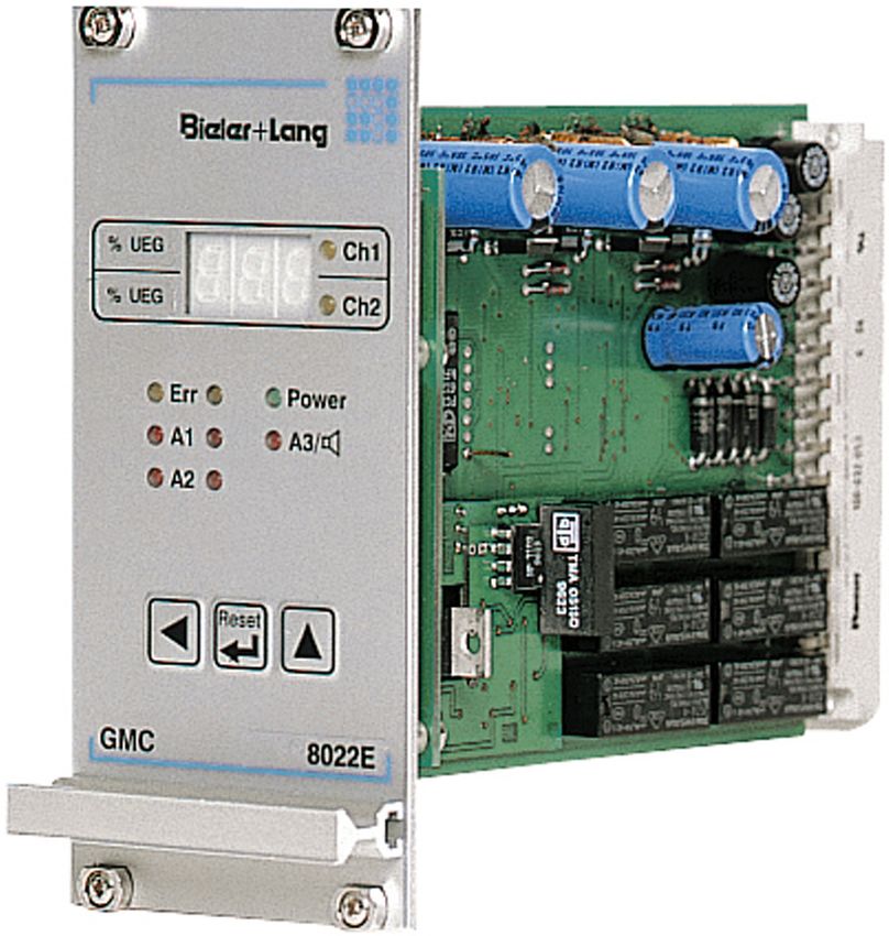
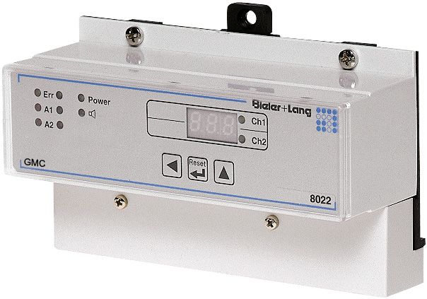
Product features ● Two versions:
- GMC 8022: for assembly in standard control cabinets
- GMC 8022E: 19" rack model
● 2 measurement channels
● Concentration display
● 2 alarm stages and additional horn output.
● Microprocessor technology provides numerous functions and simple
operation
.
● Verification of alarm signals without test gas.
● Fault monitoring for:
- Power failure
- Computer defects
- Wire breaks / short circuits in sensor leads
● Potential-free relay outputs for:
- Alarms 1 and 2
- Horns
- Faults
How it works When the system is switched on, a lamp test is carried out All LEDs illuminate
for two seconds. Then the display shows the current software version. To sup-
press a false alarm when it is switched on, the system only starts monitoring
("Auto") after a delay of 30 seconds. The display cycles between the current
concentrations at the two measurement points. The sensor being displayed is
indicated by the appropriate LED illuminating. As soon as a sensor reaches
alarm stage 1 or 2, the appropriate alarm LED blinks. When the selected alarm
delay time has expired, the appropriate alarm relay is activated. At the same
time the alarm LED becomes continuously illuminated. Because each alarm
stage has adjustable hysteresis, an alarm stage is only cancelled when the
current concentration has fallen below a second threshold. This also applies to
Alarm 2 if the system has been programmed to be "non-saving". In the other
case, Alarm 2 remains saved and can only be cleared by pressing the Reset
button. Depending on how it is programmed, when alarm stage 1 or 2 is ex-
ceeded, a horn relay output is activated. This can be cancelled immediately
by pressing the Reset button. Every time a new alarm is triggered, the horn is
immediately switched on again. In addition, an LED illuminates to show that the
horn is switched on or off. There is also the option of permanently displaying
the concentration of a particular measurement point (Stop mode). With the
19"-rack version, GMC 8022E, the 4...20mA sensor signal can be emitted con-
tinuously by means of an additional module. The system continuously monitors
whether the connection lead to a sensor is in order. An error signal is sent as
soon as a wire break or a short circuit is detected. The fault LED "Err" for the
affected measurement point illuminates and the error-signal relay is activated.
Page 2Evaluation Systems
GMC 8022 / GMC 8022 E
Data Sheet
How it works If the supply voltage is no longer adequate for the unit - or fails completely
(mains failure) - it goes into error mode and the power-LED switches off. A
lamp test can be carried out at any time by pressing the right-hand button. The
system's alarm signals can be tested without the need for test gas. To do this,
the sensors are disconnected internally from the unit to enable individual alarm
simulation. Sensors with a special calibration signal (ExDetector / Exmonitor
series) automatically activate alarm suppression to prevent false alarms during
calibration of these sensor types. During programming, the system data (horn
on Alarm 1 or 2; Alarm 2 saving or non-saving, alarm triggering of a sensor
signal on undershoot or overshoot) are first displayed as a code. The system
data can be changed. Next the number formats are defined for each measure-
ment point. Now the parameters measurement range, limits for triggering and
switching off alarm stages 1 and 2, and an alarm delay time can be set can be
set for each individual measurement point. All additional menus such as pro-
gramming, alarm simulation, or the suppression of alarm signals can only be
accessed by entering a special password.
Block wiring diagram
Digital display
AC
230 VAC
DC LED-field
Alarm 2
24 VDC Keyboard
24 VDC
Sensor 1 Alarm 1
Computer
24 VDC
Sensor 2
external
Horn
reset
Error
GMC 8022
Note: Relay shown in alarm status
Digital display
24 VDC 24 VDC
LED-field
GND
Keyboard
24 VDC
Alarm 1 Sensor 1
Sensor 1
Computer (Sensor 1+2
at group)
Alarm 2
24 VDC
Sensor 2 Alarm 1 Sensor 2
Alarm 2
external
reset
optional Horn / A3 Sensor 1+2
module4..20 ISO
Recorder
Error
module4..20 ISO
Recorder
optional
GMC 8022 E
Note: Relay shown in alarm status
Page 3Evaluation Systems
GMC 8022 / GMC 8022 E
Data Sheet
Technical data Type designation GMC 8022 GMC 8022E
Channels 2
Suitable sensors Series Exdetector, Gasmonitor, Exmonitor
EU-Type-Examination BVS 03 ATEX G 007 X
Directive 2014/34/EU
(Performance
certification)
Functional Safety SIL 1, SIL 2
(for details see separate information)
max. distance of approx 500 to 1000 m,
sensors / depending on unit configuration and sensor used.
cable cross-section See data sheet of the used sensor.
Sensor interface linear input 4...20 mA, Shunt 226 Ohm to GND
sensor power supply: 24VDC (20...27,6 VDC), SELV,
max. 100 mA for each sensor
Alarm levels Group outputs for measuring alarm 1 of each sensor
channel 1 + 2: alarm 2 of each sensor
alarm 1 and 2 horn of sensor 1 and 2
horn error of sensor 1 and 2
error
Outputs floating group alarm single / group alarm relay
alarm 1: make contact with floating contact
alarm 2: changeover - alarm 1: break contact
contact - alarm 2: break contact
error: break contact group alarm relay with
horn: make contact floating contact
- error: break contact
- horn: break contact
Make-break 230 VAC, 2A 50 VAC, 1A
capacity of output 30 VDC, 2A 75 VDC, 1A
relays
supply voltage 230 VAC, 50...60 Hz
24 VDC (21,7 ... 28 VDC) SELV
for connection to usal alternating current- / continuos
current - inverter
Current input 110 mA 150 mA
without sensors at 260 mA with connected
24 VDC 4...20 modules
Power input 14W / 20VA
Operating 0...+55°C (General applications )
temperature range 0...+40°C (Functional Safety SIL1, SIL2)
Operating humidity 0 ... 90 % rH
range
Environment Not for use more than 2000m above sea level
Protect from direct sunlight
Storage temp. -25...+55 °C
Display elements LED`s for each measuring channel:
- alarm 1 and 2
- error
- displayed sensor
ready
horn
digital indication for concentration and
programming data
Resolution of measuring range end value 100 - 999: 1
concentration measuring range end value 10,0 - 99,9: 0,1
display measuring range end value 1,00 - 9,99: 0,01
Operating elements 3 keys for:
horn and alarm reset
guidance through menus
programming
Reset input make contact for looping the internal control voltage
24 VDC, SELV
Run-in time 30 s
Update rateEvaluation Systems
GMC 8022 / GMC 8022 E
Data Sheet
Functional safety Single channel use Redundant application
Measuring function for explosion protection or
Safety function
Measurement of toxic gases or oxygen
Measuring range Depending on application and detectors connected
Operating
0 … 40 °C
temperature range
SIL Capability
1 2
Hardware
1
SIL Capability
Version 814 according DIN EN 50271
Software
(BVS 03 ATEX G 007 X)
Proof Test Intervall 1 year
Type of device B
HFT 0 1
SFF 83,28 %
ß Faktor — 5%
PFD 7,43 × 10⁻⁴ 3,78 × 10⁻⁵
λdu 1,65 × 10⁻⁷ (pro h)
λdd 5,85 × 10⁻⁷ (pro h)
λsu 2,24 × 10⁻⁷ (pro h)
λsd 1,48 × 10⁻⁸ (pro h)
MTTR 24 h
Period of use Recommended: 15 years
Application conditions
The SIL values of the controller in conjunction with the determined error proba-
bilities are only valid when the following application conditions are met:
The detectors connected must emit error signals of 3 mA as "Error low" and
22 mA as "Error high", which will be considered as failure of the appropriate
sensor. When Bieler + Lang 4-20 mA sensors are used, this is automatically
ensured. Sensors and the control unit must be commissioned by the manufac-
turer, Bieler + Lang, or by an authorised representative. The ambient condi-
tions specified in the manufacturer's documentation, e.g. with regard to tempe
rature, humidity and pressure must be observed. The sensors connected must
be regularly maintained by a qualified person and calibrated with a certified
test gas in accordance with the manufacturer's instructions. Maintenance and
calibration should be carried out in accordance with Instruction Sheet BGI 518
of the German employer's liability insurance association (= Instruction Sheet
T 023 of BG-Chemie).
Repeat testing (proof test)
The annual proof test for the control unit consists of the correct calibration of
connected sensors with a certified test gas, and checking the appropriate mea-
surements at the control unit. In addition the adjustable parameters e.g. type of
gas and alarm thresholds must be displayed and compared with the target va-
lues. All relays in the controller must be checked manually for correct switching.
Page 5Evaluation Systems
GMC 8022 / GMC 8022 E
Data Sheet
Mechanical data ● GMC 8022
Design suitable for installation in standard field
distribution or other suitable housings
Protection class IP30
Terminals 1,5 mm2
Enclosure material plastic (Lexan)
Weight approx 750 g
Dimensions (H x W x D) 94 x 157 x 60 mm
Err Power Ch1
47 mm
A1
Ch2
93 mm
A2
94 mm
Reset
GMC 8022
37 mm
60 mm 157 mm
● GMC 8022E
Design 19" plug-in unit
Connection 32-pin plug connector DIN 41612
Enclosure material front panel, aluminium
Weight approx 290 g
Dimensions 19" plug-in unit 12 TE, 3 HE
Safety of the unit Compliance with the following standards guarantees the highest degree of
safety:
● GMC 8022 and GMC 8022E:
EN 50270 Electro-magnetic Compatibility
EN 61010-1 Safety requirements for electrical equipment for
measurement, control, and laboratory use
EU Type Approval EU Type Approval Test Certificate for flammable gases BVS 03 ATEX G007 X
EN 60079-29-1
Test Certificate ●
Explosive atmospheres - Gas detectors. Performance requirements of
detectors for flammable gases
● EN 50271
Electrical apparatus for the detection and measurement of combustible
gases, toxic gases or oxygen. Requirements and tests for apparatus
using software and/or digital technologies
When used with sensors for measuring combustible gases in areas in which
there is an explosion hazard, this control unit is subject to Directive 2014/34/
EU
Page 6Evaluation Systems
GMC 8022 / GMC 8022 E
Data Sheet
Accessories ● Horns
● Warning lights
● Solenoid valves
● Central emergency power supply
● For GMC 8022E:
- Power supplies
- 4-20 mA output module
- Relay boards RK1, RK2 for switching mains power up to 2A
Service Everything from a single supplier - from project planning to installation of your
new Gas Measuring and Alarm System. Our comprehensive marketing and
service network is your guarantee. Ask us about our regional partner for your
area. And after your purchase our service technicians are always ready with
advice and assistance.
Customer-specific Our marketing specialists and service technicians are here to help solve your
measurement and control tasks. A versatile device, housing and accessory
installations programme together with decades of experience give us the knowledge
to plan and install a measurement system especially designed for your
application.
Page 7Evaluation Systems
GMC 8022 / GMC 8022 E
Data Sheet
Bieler + Lang GmbH
Gas Measurement and Warning Systems
PO Box 1129, D-77842 Achern
Von-Drais-Str. 31, 77855 Achern
Telephone +49 (0) 78 41 / 69 37 - 0
Telefax +49 (0) 78 41 / 69 37 - 99
Email info@bieler-lang.de
Technical status: 07/2017
Internet www.bieler-lang.de We reserve the right to make technical changes!
Page 8You can also read