GLCD Graphical LCD library
←
→
Page content transcription
If your browser does not render page correctly, please read the page content below
GLCD Graphical LCD library
This library makes it easy to use a Graphical LCD
(GLCD) with Arduino.
This is an extensive modification of the ks0108
library that has higher performance, more
features, supports more Arduino boards and is
easier to integrate with different panels.
Sketches written for the old library should work
with little or no modification. The configuration
mechanism has been changed to facilitate use
with a broad range of GLCD chips and ATmega
controllers. See the section on sketch migration
for details on modifications for the new library.

Table of Contents:

GLCD Graphical LCD library
 Wiring and Configuration:
 Configuration
 Troubleshooting
 Using fonts
 Using bitmaps
 Migrating your sketch from ks0108 to the new GLCD library
 GLCD Methods:
 Drawing Functions
 Text Functions

Wiring and Configuration:
Panel characteristics (like pixel height and width) and the pins used to connect to the
panel must be set in a configuration file. Configuration files are provided for the wiring
shown below, you can change the file if you want to use different wiring or panels.

This release supports panels using the KS0108 and SED1520 chips.

KS0108 family
The KS0108 is a popular controller chip used in GLCD displays, however, wiring for
these panels is not standardized and it is important to check the datasheet for your panel
to confirm how it should be wired. Incorrect connections of the signal lines are the most
common cause of problems, and particular care should be taken with the power leads as
wiring these incorrectly can destroy a panel.

Most GLCD panels require an external preset pot (variable resistor) to set the LCD
working voltage (contrast) and may require a fixed resistor to limit the current in the

                           GLCD Version 3 (Beta) Jun 9 2010
backlight. The datasheet for your panel provides specific information on the wiring and
choice of components for this.

The table below shows common pinouts for KS0108 panels.
The numbers under the Arduino column are the Arduino pins used in the configuration
file provided in the download, if you alter the wiring to Arduino pins then you must
change the pin assignments in the configuration file.

The numbers in the Panel A/B/C columns are the pin numbers of the GLCD display panel

    Arduino   Mega   Sanguino    Teensy   Teensy                 Panel Panel Panel
                                                   Function                            Comments
      pins                                 ++                     A     B      C

5V             5V      5V          5V       5V      +5 volts      1      2    13

Gnd            Gnd     Gnd        Gnd      Gnd        GND         2      1    14

n/a            n/a     n/a        n/a      n/a     Contrast in    3      3    12     Wiper of contrast
                                                                                     pot

8              22       0          0        10         D0         4      7     1

9              23       1          1        11         D1         5      8     2

10             24       2          2        12         D2         6      9     3

11             25       3          3        13         D3         7     10     4

4              26       4          13       14         D4         8     11     5

5              27       5          14       15         D5         9     12     6

6              28       6          15       16         D6         10    13     7

7              29       7          4        17         D7         11    14     8

14 (alog 0)    33       24         7        18       CSEL1        12    15    15     Chip 1 select

15 (alog 1)    34       25         8        19       CSEL2        13    16    16     Chip 2 select

Reset                                                Reset        14    17    18     Connect to reset

16 (alog 2)    35       26         6        8         R_W         15     5    10     Read/write

17 (alog 3)    36       27         5        9         D_I         16     4    11     Data/Instruction
                                                                                     (RS)

18 (alog 4)    37       28         9        7          EN         17     6     9     Enable

n/a            n/a     n/a        n/a      n/a      Contrast      18    18    17     10k or 20k preset
                                                      out

n/a            n/a     n/a        n/a      n/a     Backlight      19    19    19     See datasheet
                                                       +5

Gnd            Gnd     Gnd        Gnd      Gnd     Backlight      20    20    20     See datasheet
                                                      Gnd

                             GLCD Version 3 (Beta) Jun 9 2010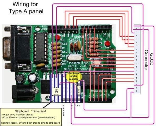
KS-0108 Pin Connections Table
                                     (see your datasheet).

The following illustrations show the wiring for these panel types with a standard Arduino
(168/328). Although the pin number on the GLCD panels are different, the corresponding
functions are connected to the same Arduino pins in all three examples so the supplied
ks0108_Config.h configuration file should work without change if you wire your panel
following the appropriate diagram.

The ks0108 datasheet says the reset pin should be taken low for a brief period after
power is applied. The diagrams show the display’s reset pin connected to the Arduino
reset pin and this will automatically reset the display when the Arduino resets. You can
also wire the display reset pin to a spare Arduino pin and control reset in software by
adding a define to the panel configuration file (see the configuration section below).
Note that some panels may function correctly without requiring an external reset; in that
case you should connect the panel reset pin to +5volts.

Note: The diagrams that follow are for standard Arduino boards (ATmega
168/328). If you have a different board then you should follow the pin assignments
in the Pin Connections Table above. See the datasheet for your panel for the value
of the backlight resistor if one is required.

                           GLCD Version 3 (Beta) Jun 9 2010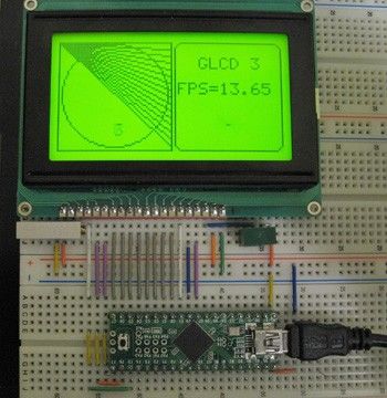
SED1520
The SED1520 uses different timing and command pins then the KS0108 and the most
common panels have fewer pixels.
The distribution contains a generic configuration file named sed1520_Config.h and an
example called Modvk5121_Config.h
for the VK5121 panel.
Here is the wiring for a typical SED1520 Panel:

                          GLCD Version 3 (Beta) Jun 9 2010
A tip for making the physical connections is use a small piece of stripboard with header
pins for 5V, Ground and Reset. The picture has an example layout for a type ’A’ panel.
GLCD Version 3 (Beta) Jun 9 2010Mega, Sanguino and Teensy boards can provide faster performance by allowing all the
data pins to be connected to the same port (actual performance will vary depending on
the panel). Note that each board type uses a different selection of pins.
Example of Teensy++ connected to
a KS0108 panel using a breadboard
Configuration
If you are using a standard Arduino board (168/328) or a Mega, Sanguino, Teensy, or
Teensy++; and you have a 128x64 KS-0108 panel wired according to the pin connections
table above, you don’t need to make any changes to configuration files.
If you use different wiring or use a different panel type you will need to modify one of
the supplied configurations or you can create your own. These configuration files set the
panel parameters (display height, and width, timing, etc) to match your hardware and
allows selection of the Arduino pins used to connect to the display.
Although display panel timing can also be easily configured, most displays will work
without requiring a configuration change for timing. However, you should check the
datasheet for your panel to verify the timing values in the panel configuration file.
The active configuration when the sketch is compiled is selected in a master
configuration file named glcd_Config.h.
The default configuration file (named "config/ks0108_Panel.h") is for 128x64
ks0108 type panel.
The panel configuration file naming is:
"{PANELNAME}_Panel.h"
Where:
{PANELNAME} is the glcd panel type. (for example, ks0108)
GLCD Version 3 (Beta) Jun 9 2010The panel configuration file includes a board specific configuration file that specifies the
pins used for each specific board type.
The pin configuration file naming is a follows:
"{PANELNAME}_{BOARDNAME}.h"
{PANELNAME} is the glcd panel type. (for example, ks0108)
{BOARDNAME} is the name of the board (as selected in the Arduino IDE).
For example, the ks0108 pin configuration file name for a standard Arduino board is:
"ks0108_Arduino.h"
The equivalent file for the "Mega" board is: "ks0108_Mega.h"
If you change the active configuration in the master configuration file glcd_Config.h,
make sure that one and only one configuration file is included.
Processor type is automatically determined from the board selected when the sketch is
built, this allows Arduino style pin numbers to be mapped to fast direct port IO used by
the library.
Pin numbering for the following processor types are supported:
- Standard Arduino (ATmega8,168,328)
- Mega(ATmega1280)
- Sanguino (ATmega644P)
- Teensy and Teensy++ (AT90USB646, AT90USB1286, ATmega32U4)
In summary:
glcd_Config.h includes a panel file "config/{PANELNAME}_Panel.h" (the active
configuration) that in turn includes a board specific pin mapping file based on arduino
board type, "config/{PANELNAME}_{BOARDNAME}.h"
GLCDdiags
GLCDdiags is a test sketch included in the examples folder. It will validate the
connections and test the memory of GLCD module as well as report the active
configuration information to the serial port. If your display is not working properly then
check the information displayed in the serial monitor. The sketch prints the information
the library is using to the serial monitor and you can use this to verify if the sketch is
configured correctly.
AVR port and pin numbers
Pins can also be selected by AVR port and pin number. The syntax used is PIN_Pb where
Pb represents a PORT and a bit#.
For example, to specify port D bit 3 you would use PIN_D3
The following sets glcdCSEL1 (the first chip select) to port D pin 3
#define glcdCSEL1 PIN_D3
See the avrio.h file for more details.
GLCD Version 3 (Beta) Jun 9 2010Troubleshooting
No pixels visible on the display
•Check +5v and Gnd connections between Arduino and GLCD panel
•Check all data and command pins are wired according to the datasheet and matching the
configuration settings – this is the most common cure to this problem.
•Check the datasheet for your panel to verify appropriate timing values are set in the
configuration file.
•Check contrast voltage (typically between -3 and -4 volts) on contrast-in pin of LCD
panel. While the sketch is operating, try gradually adjusting the pot through its range.
Some displays are very sensitive to this setting.
•Check that sketch has compiled correctly and has downloaded to Arduino.
•Run GLCDdiags test sketch, see Configuration section above.
Left and right side of image reversed
•Swap CSEL1 and CSEL2 wires (or swap pin assignments in the configuration file)
Display garbled
•Check all data and command pins are wired correctly and that these match the setting in
the configuration file.
•Check the datasheet for your panel to verify appropriate timing values are set in the
configuration file.
Using fonts
There is a free java application available that can convert PC fonts for use with this
library. The software is called FontCreator2 and it can produce a header file that can be
included in your sketch. The header files should be placed in the directory named fonts
and included in your sketch. For example, if you create a font named myfont in a header
named myfont.h then copy myfont.h to the fonts directory and in your sketch:
#include "fonts/myfont.h" // system font
To use the font in your sketch you select the font as follows:
GLCD.SelectFont(myfont); // use myfont
Note that the distribution contains a file named allFonts.h that includes all the distributed
fonts, so you can include these files instead of explicitly including the individual fonts
#include "fonts/allFonts.h" // all distributed fonts
Font definitions are stored in program memory and this can be significant for larger fonts.
The 7 pixel high system font uses under 500 bytes, the supplied Arial14 font uses 1200
bytes of program memory
Using bitmaps
You can use the distributed bitmaps or create your own. The distribution contains a file
named allBitmaps.h that includes all the distributed bitmaps, so you can include this to
make the bitmaps available:
GLCD Version 3 (Beta) Jun 9 2010#include "bitmaps/allBitmaps.h" // all distributed bitmaps
Note that included bitmaps will not consume any memory if they are not explicitly
referenced in your sketch with the DrwBitmap function.
You can also display your own images in your sketch. A utility named glcdMakeBitmap
converts a gif, jpg, bmp, tga or png file to a header file that can be read by the glcd
library. glcdMakeBitmap.pde is a sketch that can be run using the Processing
environment (its in the bitmaps/utils/glcdMakeBitmap directory. For more information on
Processing, see: http://processing.org/
There is a java runtime file (glcdMakeBitmap.jar) and java source
(glcdMakeBitmap.java) in thee bitmaps/utils/Java directory
Run the utility by loading the pde into Processing (or click on the jar file) and drag and
drop the image file to be converted into the window.
glcdMakeBitmap window after dropping an image named
arduinoIcon.
If the image can be converted, a header file is created in the bitmap directory.
For example, if the image file name to be converted is named image.bmp, the header is
named image.h
Add the following line to the sketch:
#include "bitmaps/image.h"
and display the image using the following code:
GLCD.DrawBitmap(image, x, y);
where x and y are the desired location of the upper left edge of the bitmap.
Images are stored in program memory, a 128x64 pixel image takes 1k bytes of flash.
Bear in mind that each different image used in a sketch will reduce the amount of code
available to a sketch. glcdMakeBitmap displays the amount of memory required for the
image and other useful information when it does the conversion.
Migrating your sketch from ks0108 to the new GLCD library
The GLCD library is an extensive modification of the ks0108 library. It now supports
more chips and is easier to integrate with different panels. The graphical functions are
backwards compatible (except where noted) so existing sketches should work with little
or no modification to the code.
The configuration mechanism has been changed to facilitate use with a broad range of
GLCD chips and ATmega controllers. If your wiring does not match the default pin
GLCD Version 3 (Beta) Jun 9 2010assignments you will need to need to modify the configuration files in the new library to
match your wiring.
The distribution includes the system font and arial14 fonts that were distributed with the
previous version, but these are now in a subdirectory called ‘fonts’ so you will need to
modify the include statement:
change
#include "SystemFont5x7.h" // system font
to
#include "fonts/SystemFont5x7.h" // system font
Bitmaps are now in a bitmaps subdirectory and the file names include the width and
height; so change :
#include "ArduinoIcon.h" // the bitmap distributed with the ks0108 lib
To
#include "bitmaps/ArduinoIcon64x64.h" // 64x64 bitmap
The ArduinoIcon.h bitmap file was renamed to ArduinoIcon64x64.h to differentiate it
from other size bitmaps supplied for panels of different pixel dimensions.
If you are using any of the following functions you should either change the code use the
new function or include glcd_Deprecated.h file that will convert the old function name to
the new function.
DrawVertLine(x, y, length, color) is now: DrawVLine(x, y, length, color)
DrawHoriLine(x, y, length, color) is now : DrawHLine(x, y, length, color)
ClearSysTextLine(row) is now EraseTextLine(row)
The character output functions behave differently in the new library.
The new library now sets or clears all pixels of a font (glyph), the old library did not
consistently erase pixels in the whitespace below the glyph.
This means that if there are graphics very close below the character they may be
overwritten with the new text ouput code.
The workaround is to either move the graphics objects so they are not cleared when the
text is written or to draw the graphical objects after the text is displayed.
Another change is the way a string wraps on the newline character. The old library
wrapped to the column where the string started, the new library now wraps to the
beginning of the text area. See the section on Text Areas to see how you can use this new
capability to control where text will wrap on the display.
See the section on Configuration for details on the new configuration files. You can use
the same wiring as the old library but the configuration file format has changed. The
ks0108_Config,h file included in the distribution uses exactly the same pins as the
ks0108_Arduino.h file supplied with the old library, but if you changed the Arduino pin
numbers you will need to modify ks0108_Config to match your wiring.
GLCD Version 3 (Beta) Jun 9 2010GLCD Methods:
Here is a summary of the methods supported by this library.
Note that all coordinates start from 0 unless otherwise noted. 0,0 is the pixel on the upper
left edge of the screen
Table of contents
GLCD Graphical LCD library
Wiring and Configuration:
Configuration
AVR port and pin numbers
Troubleshooting
Using fonts
Using bitmaps
Migrating your sketch from ks0108 to the new GLCD library
GLCD Methods:
Init()
SetDisplayMode()
ClearScreen()
ReadData()
WriteData()
Drawing Functions
Coordinate system
Properties
Colors
GotoXY()
SetDot()
DrawVLine()
DrawHLine()
DrawLine()
DrawRect()
FillRect()
InvertRect()
DrawRoundRect()
DrawCircle
FillCircle()
DrawBitmap()
Text Functions
SelectFont()
SetFontColor()
SetTextMode()
ClearArea()
EraseTextLine(row)
EraseTextLine()
CursorToXY()
Arduino print functions
GLCD Version 3 (Beta) Jun 9 2010Text Areas
DefineArea()
Enhanced print functions
printFlash ()
printFlashln ()
Printf ()
Printf_P ()
CharWidth()
StringWidth()
StringWidth_P()
Legacy text output functions
PutChar()
Puts()
PrintNumber()
Puts_P()
Init()
Description: This should be called in setup to initialize the library prior to calling any
other function.
The display is cleared and ready for use after calling Init.
Syntax
GLCD.Init() ; // initialize the library to draw dark pixels on a light
background
GLCD.Init(NON-INVERTED) ; // same as above
GLCD.Init(INVERTED) ; // initialize the library to draw light pixels on a dark
background
Parameters
Init with no parameter is the standard initialization, this is identical to: Init(NON-
INVERTED)
Init(INVERTED) will invert dark and light pixels when drawn
SetDisplayMode()
Description: sets the graphical state to normal (BLACK colored pixels are dark), or
inverted (WHITE colored pixels are dark)
Syntax
GLCD.SetDisplayMode(NON_INVERTED); // sets the state to normal
GLCD.SetDisplayMode(INVERTED); // sets the state to inverted
(Note this function was named SetInverted() in the previous library releases)
GLCD Version 3 (Beta) Jun 9 2010ClearScreen()
Description: Erases all screen pixels (pixels from 0,0 to GLCD.Width-1,GLCD.Height-
1)
Syntax
GLCD.ClearScreen(); // sets all pixels to WHITE (if NORMAL mode or BLACK if
INVERTED)
GLCD.ClearScreen(WHITE); // same as above
GLCD.ClearScreen( BLACK); // clears screen writing BLACK pixels
Note: If the display is in INVERTED mode, then the color WHITE will paint the screen
BLACK and the color BLACK will paint the screen WHITE.
ReadData()
Description: Returns the data byte at the current x,y location
Syntax:
GLCD.ReadData(); // return the byte of data at the current x,y location
See also: GotoXY();
WriteData()
Description: Writes the given byte of data at the current x,y location
Syntax:
GLCD.WriteData( data);
GLCD Version 3 (Beta) Jun 9 2010Drawing Functions
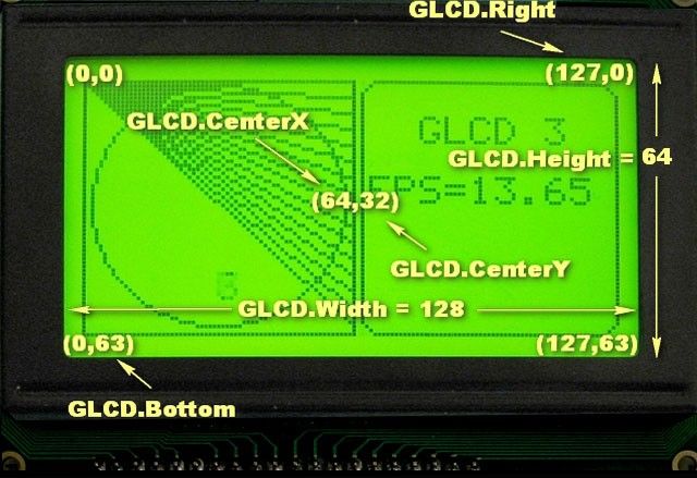
Coordinate system
0,0 is the upper left edge of the display.
GLCD.Width is the width of the display in pixels
GLCD.height is the height of the display in pixels
GLCD.Right is the right-most pixel (equals GLCD.Width-1)
GLCD.Bottom is the bottom pixel (equals GLCD.Height-1)
GLCD.CenterX is the horizontal center (equals GLCD.Width/2)
GLCD.CenterY is the vertical center (equals GLCD.Height/2)
GLCD Version 3 (Beta) Jun 9 2010Properties
GLCD.Width - the display width in pixels
GLCD.Heigh - the display height in pixels
GLCD.Right - the display width -1
GLCD.Bottom - the display height -1
GLCD.CenterX - half of the display width
GLCD.CenterY- half of the display height
Colors
Two colors are supported in this version.
BLACK is a dark pixel, WHITE is a pixel that is not dark
BLACK is the default color
GotoXY()
Description: moves the graphics cursor to the given x,y coordinates.
Syntax
GLCD.GotoXY(x,y);
Parameters
x – a value from 0 to GLCD.Width-1
y - a value fron 0 to GLCD.Height-1
SetDot()
Description: sets the pixel at the given x,y coordinate to the given color
Syntax
GLCD.SetDot(x,y, BLACK); // draws a BLACK pixel at x,y
GLCD.SetDot(x,y, WHITE); // erases the pixel at x,y
Parameters
x – a value from 0 to GLCD.Width-1
y - a value fron 0 to GLCD.Height-1
DrawVLine()
Description: Draws a vertical line
Syntax
GLCD.DrawVertLine(x, y, height); // draws a BLACK line from x,y to x, y + height
GLCD.DrawVertLine(x, y, height, BLACK); // as above
GLCD.DrawVertLine(x, y, height, WHITE); // as above but the pixels on the line are
erased
GLCD Version 3 (Beta) Jun 9 2010Parameters
x – a value from 0 to GLCD.Width-1
y - a value from 0 to GLCD.Height-1
height – a value from 1 to GLCD.Height-y-1
BLACK or WHITE is an optional parameter indicating pixel color, default is BLACK
(Note this function was named DrawVertLine() in the previous library releases)
DrawHLine()
Description: Draws a horizontal lines
Syntax
GLCD.DrawHoriLine(x, y, width); // draws a BLACK line from x,y to x + width , y
GLCD.DrawHoriLine(x, y, width, BLACK); // as above
GLCD.DrawHoriLine(x, y, width, WHITE); // as above but the pixels on the line are
erased
Parameters
x – a value from 0 to GLCD.Width-1
y - a value from 0 to GLCD.Height-1
width – a value from 1 to GLCD.Width-x-1
BLACK or WHITE is an optional parameter indicating pixel color, default is BLACK
(Note this function was named DrawHoriLine() in the previous library releases)
DrawLine()
Description: Draws a line between two coordinates.
Syntax
GLCD.DrawLine( x1, y1, x2, y2; // draws a BLACK line from x1,y1 to x2,y2
GLCD.DrawLine( x1, y1, x2, y2, BLACK); // as above
GLCD.DrawLine( x1, y1, x2, y2, WHITE); // as above but the pixels on the line are
erased
Parameters
x1 – a value from 0 to GLCD.Width-1 indicating start x coordinate
y1 - a value fron 0 to GLCD.Height-1 indicating start y coordinate
x2 – a value from 0 to GLCD.Width-1 indicating end x coordinate
y2 - a value fron 0 to GLCD.Height-1 indicating end y coordinate
BLACK or WHITE are optional parameters specifying pixel color, default is BLACK
GLCD Version 3 (Beta) Jun 9 2010DrawRect()
Description: Draws a rectangle of given width and height
x,y is the upper left edge of the rectangle
The lower right edge is at x+width, y+height
Note that the length of the horizontal sides will be width+1 pixels, the vertical sides will
be height+1 pixels
Syntax
GLCD.DrawRect( x, y, width, height); // draws a BLACK rectangle of given
width and height starting at x,y
GLCD.DrawRect( x, y, width, height, BLACK); // as above
GLCD.DrawRect( x, y, width, height, WHITE); // as above but the rectangle pixels
are erased
Parameters
x, y – the x,y coordinates of the rectangle to be drawn
width, height – the width and height of the rectangle
FillRect()
Description: Fills the interior of a rectangle specified by a pair of coordinates, a width,
and a height.
The left and right edges of the rectangle are at x and x + width - 1.
The top and bottom edges are at y and y + height - 1.
The resulting rectangle covers an area width pixels wide by height pixels tall starting
from the pixel at x,y.
The rectangle is filled using the given color (BLACK if none given)
(Note that FillRect behavior has changed from the previous versions of the library. The
filled rectangle will be one pixel smaller in width and height than the old version. This
change was to make the functionality consistent with the way Java and C# create filled
rectangles)
Syntax
GLCD.FillRect( x, y, width, height);
GLCD.FillRect( x, y, width, height, BLACK); // as above
GLCD.FillRect( x, y, width, height, WHITE); // as above but the rectangle pixels are
erased
InvertRect()
Description: Sets BLACK pixels WHITE and WHITE pixels BLACK within the given
rectangular area.
The left and right edges of the inverted area are at x and x + width - 1.
The top and bottom edges are at y and y + height – 1
GLCD Version 3 (Beta) Jun 9 2010Syntax
GLCD.InvertRect( x, y, width, height); // inverts pixels in the given rectangular area
Parameters
As FillRect but without the color parameter
DrawRoundRect()
Description: Draws a rectangle with rounded corners
Syntax
GLCD.DrawRoundRect( x, y, width, height, radius); // draws a BLACK rectangle
similar to DrawRect but with corners of the given radius
GLCD.DrawRoundRect( x, y, width, height, radius, BLACK); // as above
GLCD.DrawRoundRect( x, y, width, height, radius, WHITE); // as above but the
rectangle pixels are erased
Parameters
x,y,width,height as DrawRectangle
radius- a value from 1 to half the height or width of the rectangle
DrawCircle
Description: Draws a circle centered at x,y with the given radius
The circle will fit inside a rectangular area bounded by x-radius,y-radius and
x+radius,y+radius
Note that because the circle is drawn from the center pixel out, the diameter will be 2 *
radius +1 pixels.
Syntax
GLCD.DrawCircle( x, y, r); // draws a BLACK circle centered at x,y with radius r
GLCD.DrawCircle( x, y, r, BLACK); // as above
GLCD.DrawCircle( x, y, r, WHITE); // draws a WHITE circle centered at x,y with
radius r
Parameters
x – a value from 0 to GLCD.Right (GLCD.Width-1)
y - a value fron 0 to GLCD.Bottom (GLCD.Height-1)
radius- a value from 1 to half the height or width of the rectangle
FillCircle()
Description: Draws a filled in circle centered at x,y with the given radius
Syntax and Parameters
GLCD Version 3 (Beta) Jun 9 2010see DrawCircle
DrawBitmap()
Description: Draws a bitmap image with the upper left edge at the x,y coordinates.
Bitmap data is in program memory (Flash)
A utility for creating bitmap header files, glcdMakeBimtap, is supplied with the
download
Syntax
GLCD.DrawBitmap(*bitmap, x, y);
GLCD.DrawBitmap(*bitmap, x, y, BLACK); // as above
GLCD.DrawBitmap(*bitmap, x, y, WHITE); // inverts pixels
Text Functions
SelectFont()
Description: Selects the font definition as the current font. Subsequent printing functions
will use this font. Font definitions are stored in program memory.
You can have as many fonts defines as will fit in program memory and can switch
between them with this function.
Syntax
GLCD.SelectFont( font) ; // font is a font pointer defined in a font definition
file. Output is rendered using dark pixels.
GLCD.SelectFont( font, BLACK) // as above
GLCD.SelectFont( font, WHITE) // printed output rendered as WHITE pixels
SetFontColor()
Description: Sets the color of the currently selected font.
Syntax
GLCD.SetFontColor( BLACK) // printed output rendered as BLACK pixels
GLCD.SetFontColor( WHITE) // printed output rendered as WHITE pixels
GLCD.SetTextMode()
Description: // Sets the given text mode (currently only scroll direction is supported)
Syntax
GLCD.SetTextMode(SCROLL_UP) // normal scroll direction, old lines scroll up
GLCD.SetTextMode(SCROLL_DOWN) // reverse scroll direction, old lines scroll down
GLCD Version 3 (Beta) Jun 9 2010SetTextMode()
Description: // Sets the given text mode (currently only scroll direction is supported)
Syntax
GLCD.SetTextMode(SCROLL_UP) // normal scroll direction, old lines scroll up
GLCD.SetTextMode(SCROLL_DOWN) // reverse scroll direction, old lines scroll down
ClearArea()
Description: clears the current text area using the current font background color. The
cursor is set to the upper left corner.
Syntax
GLCD.ClearArea(); // clears the text area and sets the cursor to the upper left corner of
the text area
EraseTextLine(row)
Description: clears all text on the given row within the text area, moves the cursor to the
left position.
EraseTextLine()
Description: clears text on the current line, default is to clear from the cursor to the end of
the text area
Syntax
GLCD.EraseTextLine(); // erase from cursor to end of line
GLCD.EraseTextLine(eraseTO_EOL); // as above
GLCD.EraseTextLine(eraseFROM_BOL); // erase from beginning of line to cursor
GLCD.EraseTextLine(eraseFULL_LINE); // erase the entire line
CursorTo()
Description: move the cursor to the given row and column. When variable width fonts
are used, the column calculation uses the width of the widest character.
Syntax
GLCD.CursorTo( column, row); // 0 based coordinates for character columns and rows
CursorToXY()
Description: moves the text cursor to the coordinates given by x,y relative to the upper
left corner.
Syntax
GLCD.CursorToXY( x,y);
GLCD Version 3 (Beta) Jun 9 2010DrawString(str, x, y);
Description: prints the given string of characters starting from the given x and y
coordinates. The coordinates are relative to the text area- use a text area covering the full
display if you want the x,y parameters to be the same as the coordinates for Graphical
functions like GotoXY.
DrawString_P(ProgMemString, x, y);
Description: as above but the string is defined in Program memory (flash)
Arduino print functions
All of the Arduino print functions can be used in this library, see:
http://www.arduino.cc/en/Serial/Print
The functions work with any selected font.
All of these functions print from the current cursor position (see GotoXY and CursorTo)
GLCD. print(character); // prints the character at the current cursor position
GLCD. print(integer); // prints the decimal value of the integer
GLCD. print(integer,DEC); // as above
GLCD. print(integer, HEX); // prints the hexadecimal value of the integer
GLCD. print(integer, OCT) ; // prints the octal value of the integer
GLCD. print(integer, BIN) ; // prints the binary value of the integer
GLCD. print(integer, BYTE); // prints the ASCII character represented by the integer
GLCD. print(float); // prints a floating point number using two decimal places
GLCD. print(float, digits); // prints a floating point number using the given number of
digits after the decimal point
GLCD. print(string) ; // prints the string
The println variants of these functions are also supported. GLCD. println(variable); will
wrap to the next
line at the end of the print.
Printing strings can consume a lot of RAM. Printing strings using the flashStr prefix
results in the compiler using flash rather than RAM to store the string
GLCD. print(“string”) ; // string stored in RAM: the compiler reserves 7 bytes of RAM
(string length + 1) to store the string
GLCD. print(flashStr(“string”) ) ; // stores the string in Flash memory (Progmem) , no
RAM is used to store the string
GLCD. println(flashStr(“another string”) ) ; // as above, but wraps following text to the
next line
Text Areas
All of the text functions described above can be applied to a select rectangular area of the
screen, called a text area.
GLCD Version 3 (Beta) Jun 9 2010A text area acts like a virtual terminal and text output is displayed within the confines of
a rectangle given in the DefineArea command.
For example:
gText textTop = gText(textAreaTOP); // create a text area covering the top half of the
display
gText myTextArea = gText(GLCD.CenterX-16, GLCD.CenterY -16, GLCD.CenterX
+16, GLCD.CenterY+16); // create a text area covering the center 32 pixels of the display
All of the text functons operate on a text area by using the text area name instead of
‘GLCD’, for example:
textTop.SelectFont(System5x7); // select the system font for the text area name textTop
textTop.println(“a line of text”); // print a line of text to the text area.
See the download sketches for more example usage.
Text Areas are created using one of the three Define Area methods described below:
DefineArea()
Description: defines the rectangular area for text output.
The rectangular area can be specified using either: a predefined area , an area determined
by a given number of rows and columns of the given font, or a rectangular area specified
by the upper left and lower right pixel coordinates.
Syntax
DefineArea( preDefinedArea, scrollDirection); // create a text area using one of the
predefined values
preDefinedArea is one of: textAreaFULL, textAreaTOP, textAreaBOTTOM,
textAreaLEFT, textAreaRIGHT,
textAreaTOPLEFT,textAreaTOPRIGHT,textAreaBOTTOMLEFT,textAreaBOTTOMRI
GHT.
scrollDirection can be SCROLL_UP or SCROLL_DOWN, if scrollDir is omitted the
direction will be SCROLL_UP.
DefineArea( x1, y1, columns, rows, font, scrolldirection);
As above but the height and width of the area is determined by the number of columns
and rows for the given font.
For proportional (variable width) fonts, the width of widest character is used.
DefineArea( x1, y1, x2, y2, scrolldir); (or width,height as you prefer
As above but x1, y1, x2, y2, determine the rectangular area of the text window
GLCD Version 3 (Beta) Jun 9 2010All of the Text functions listed above can be used with user defined areas. The following
fragment (from the glcdDemo example sketch) creates a text area in the center of the
screen using the Arial_14 font that is holds a single character ( one column wide by one
row high):
gText countdownArea = gText(GLCD.CenterX, GLCD.CenterY,1,1,Arial_14); //
declare text area for a single digit
countdownArea.ClearArea(); // clear the text area
countdownArea.print(count); // print a digit in the text area
Enhanced print functions
printFlash ()
Description: Allocates and prints a string in Flash (program memory)
Syntax
GLCD.printFlash(string);
printFlashln ()
Description: As printFlash but wraps following text to the next line
Syntax
GLCD.printFlashln( string);
Printf ()
Description: Writes a sequence of data formatted as specified by the format argument.
The format string uses standard printf() formating % tags, but floating point is not
supported.
Syntax
GLCD.Printf( format, arguments …);
The format string contains text or optional embedded format tags. The argument list types
must match the format tags.
Users not already familiar with using printf are advised that the standard Arduino print
functions are simpler to use.
Printf_P ()
Description: as Printf above but the format string is stored in Flash instead of RAM
Syntax
GLCD.Printf_P( format, arguments …);
See Printf()
GLCD Version 3 (Beta) Jun 9 2010CharWidth()
Description: returns the width in pixels of the given character including any inter-
character gap pixels following the character when rendered on the display.
Syntax
byte width = GLCD. CharWidth(c);
StringWidth()
Description: returns the width in pixels of the given string in the currently selected font
Syntax
byte width = GLCD. StringWidth(string);
StringWidth_P()
Description: returns the width in pixels of the given string stored in program memory
Syntax
byte width = GLCD. StringWidth_P(PgmStrring);
Legacy text output functions
The following functions are supported for backward compatibility with previous library
versions, the GLCD.print functions are compatible with Serial.print routines.
and have more functionality.
PutChar()
Description: prints the given character at the current cursor position. It is suggested that
the Arduino print character function,
GLCD.print(character) is used in new applications – it has identical functionality with the
benefit of similar syntax to other arduino print methods.
Note that there is a subtle difference in the way this function handles the newline
character compared to the ks0108 library. The old PutChar() would treat the newline
character just like any other character and since many fonts don't don’t have a glyph
defined for the newline its would be thrown away.
The new PutChar() does newline processing and will wrap and potentially scroll the text
window.
Syntax
GLCD. PutChar(c); // print the character c at the current cursor position (same as
GLCD.print(c);
GLCD Version 3 (Beta) Jun 9 2010Puts()
Description: prints the given string of characters starting from the current cursor position.
Note that the old library would process newlines in Puts(). It would wrap to the text line
below the current line but back to the X position where string printing started.
The new code lets PutChar() process the newlines and so a new line will wrap to the line
below but will wrap to the start X position of the text window rather than the X position
when the Puts()started.
Also, the old Puts() assumed zero padding below a font while the new Puts() handles
padding consistently across all the functions.
So the new Puts()/Putchar() will wrap 1 pixel lower than the old Puts() routine.
Syntax
GLCD. Puts(string); // // print the string at the current cursor position (same as
GLCD.print(string);
PrintNumber()
See GLCD.print(number);
Puts_P()
Description: prints a string stored in program memory starting form the current cursor
position.
Syntax
GLCD. Puts_P(progMemString);
Note that the string being printed must already be defined as a program memory string.
See also printFlash which allocates and prints the string in program memory
GLCD Version 3 (Beta) Jun 9 2010You can also read