GRAIL: A General Purpose Real Time Localization System: Version 1.0
←
→
Page content transcription
If your browser does not render page correctly, please read the page content below
Please do not remove this page

GRAIL: A General Purpose Real Time Localization
System: Version 1.0
Chen, Yingying; Moore, Robert; Elnahrawy, Eiman; et.al.
https://scholarship.libraries.rutgers.edu/discovery/delivery/01RUT_INST:ResearchRepository/12643453950004646?l#13643526010004646

Chen, Y., Moore, R., Elnahrawy, E., Kleisouris, K., Francisco, J.-A., Li, X., Chandrasekaran, G., Turgut, B., &
Martin, R. P. (2007). GRAIL: A General Purpose Real Time Localization System: Version 1.0. Rutgers
University. https://doi.org/10.7282/T3474F5W

This work is protected by copyright. You are free to use this resource, with proper attribution, for
research and educational purposes. Other uses, such as reproduction or publication, may require the
permission of the copyright holder.
Downloaded On 2021/10/27 01:46:46 -0400
GRAIL: A General Purpose Real Time Localization System:
                            Version 1.0
                          Yingying Chen1 , Robert S. Moore2 , Eiman Elnahrawy3 ,
                       Konstantinos Kleisouris2, John-Austen Francisco2 , Xiaoyan Li4 ,
                      Gayathri Chandrasekaran2 , Begumhan Turgut2 , Richard P. Martin2
                                           1
                                           yingying.chen@stevens.edu
                  2
                      {romoore,kkonst,deymious,gayathri,bturgut,rmartin}@cs.rutgers.edu
                                             3
                                               eiman@kordinate.com
                                              4
                                                xili@cs.lafayette.edu
                         1                                   2
                           Dept. of ECE                        Dept. of Computer Science
                         Stevens Institute of Technology Rutgers University
                         Hoboken, NJ 07030                   Piscataway, NJ 08854
                        3                                       4
                         Kordinate LLC                           Dept. of Computer Science
                        402 Main St. Ste. 100-213               Lafayette College
                        Metuchen, NJ 08840                      Easton, PA 18042

          Rutgers University Department of Computer Science Technical Report DCS-TR-619
                                           October 2007

                                                        Abstract
          This paper describes a general purpose Real Time Location System (RTLS), GRAIL, version 1.0. GRAIL
      provides real-time, adaptable, indoor localization for wireless devices. Because GRAIL’s focus is to localize
      as diverse a set of devices as possible, it utilizes a centralized, anchor based approach. GRAIL defines
      an abstract data model for various system components to support different physical modalities and various
      localization algorithms. We show through real deployments that GRAIL functions over a variety of physical
      modalities, networks, and algorithms. Further, we found that a centralized solution has critical advantages
      over distributed implementations for handling privacy concerns. A contribution of this system is its universal
      approach: it can integrate different hardware and software capabilities within a single localization framework.
      The deployment of such a system in academic and research environments allows researchers to explore issues
      beyond algorithms and investigate effects in real deployments.

1 Introduction
Technology trends have reduced the cost of wireless networking to the point where it can be added to nearly
every computing device. Indeed, wireless networking devices include laptops, PDAs, small sensors, active RFID
tags, and even cameras and printers. The inclusion of wireless networking in such a broad range of devices opens
an opportunity for a new computing service: positioning devices in physical space. A generic service of this kind
would enable a host of additional applications, ranging from such diverse areas as asset management, disaster
recovery, inventory tracking, geometry-based routing, and perimeter-based security. Using the same wireless
traffic for both communication and positioning would provide tremendous cost and deployment savings over an
independent localization infrastructure.
  In this paper we present the GRAIL system, which has the explicit goal of providing location information about
any wireless transmitter [1]. The field of localization covers a broad range of topics, from lower-layer physical

                                                            1
Figure 1: GRAIL system architecture
problems to high-level application services. Within this extensive area, GRAIL focuses on performing general-
purpose localization in building-sized environments. The GRAIL system is designed to have the following
properties:
• General Purpose. A primary goal of the GRAIL system is that it should work over a variety of physical
modalities, networks, and algorithms. Just as networking systems support multiple media access layers,
routing protocols, and applications, a general purpose localization system should support multiple physical
modalities and localization methods in order to support a diverse set of applications.
GRAIL is designed to localize using any wireless network that supports physical layer measurements of
packet data. It currently supports the use of Received Signal Strength (RSS) as the physical modality and
can easily be extended to support Angle-Of-Arrival (AOA), and Time-Of-Arrival (TOA).
• Real-time. Latency is a key property of localization systems because it defines the maximum mobility
that can be supported. Our system can return results in less than one second, allowing us to support both
stationary devices as well as those moving at walking speeds (about 1m/s).
• Adaptable. Indoor environments are especially challenging due to reflections, refractions, and scattering,
which result in substantial multi-path effects. GRAIL is designed to manage the uncertainty of these
effects by expanding or contracting the confidence in the position estimate in accordance with the quality
of the underlying observations. In addition, GRAIL supports dynamic feedback in the position estimates
in order to dynamically scale the position uncertainty to the quality of recent observations.
• Indoor. GRAIL is designed to scale to the set of indoor environments controlled by a single organiza-
tion; e.g., a campus. Integration of the location information with outdoor systems, such as GPS, is the
responsibility of higher layers.
The rest of this paper is organized as follows: We first provide a system overview of GRAIL in Section 2.
Then, in Sections 3, 4, 5, 6, and 7, we describe each of the system components in GRAIL, including landmarks,
the server, solvers, the database, and the web server. Further, we present our experiences in deploying GRAIL
in Section 8. In Section 9, we place our work in the context of the broader localization literature. Specifically,
we compare our work with other existing localization systems. Finally, we conclude our work in Section 10.
2 Overview of the GRAIL System
System Architecture
Figure 1 shows the architecture of the GRAIL system. The main system components are transmitters, land-
marks, the server, solvers, the database, and the web server. In the figure, each square is realized as a separate
process. Note that in this work, we use the OSI/IP model when referring to communication layers.
2proach. In this approach, special nodes called landmarks are deployed at known locations. They continuously
monitor the channels’ traffic at the packet-level and forward their observations to a central entity, the server. The
localization process begins once the transmitters send packets. Landmarks are sometimes called Anchor Points
or Access Points. In GRAIL, however, we use the term landmark, because Access Points provide access to the
wired network while in GRAIL landmarks need only observe radio packets.
The anchor-based strategy removes the need to install special-purpose software on the devices to be localized.
It also allows users to rapidly incorporate new devices. Specifically, we have used the GRAIL system to simul-
taneously localize multiple devices running 802.11 [2], 802.15.4 [3] and Roll-Call [4] protocols, with little to no
software modifications. We compare and contrast our strategy to others, (e.g., hop-by-hop) in Section 9.
The next step in the localization process is for the landmarks to extract the time when the packet was received,
the RSS, and possibly the AOA, and send them to the server along with other packet header information.
Upon receiving the RSS readings and timestamps from each landmark, the server collects the complete set of
RSS readings for each transmitter, cleans up the data samples, decides on which localization algorithm to use,
and then forwards the information to an instance of the solver. The solver estimates the locations and sends them
back to the server, which it then stores in the database.
Key Abstractions
The GRAIL system uses an abstract data model of various system components. Understanding this model is
critical for understanding the localization process. GRAIL divides the model into two levels:
• Low-level: The low-level abstractions describe raw packet information. This kind of data includes packet
arrival time, signal strength, and angle-of-arrival. These abstractions, including transmitters, samples,
timestamps, RSS values, and AOA information, are utilized by the system for higher-level processing.
For instance, a transmitter is a network device that transmits radio frequency packets, and is identified by
its layer-2 or layer-3 address. The timestamp represents the time at which a packet is observed. The RSS is
the RSS reading embedded in a packet, while AOA is for the reported angle. A sample aggregates a group
of these low-level observations, including a timestamp, RSS, and potentially AOA, for some transmitter.
The landmarks are responsible for transforming the modality- and network-dependent data into these low-
level abstractions. For example, a landmark would have to read a packet header and extract the TOA and
RSS of the packet. The landmark then forwards samples, built from these low-level abstractions, to the
server.
• High-level: The GRAIL system further models higher-level objects built from the low-level abstractions.
These are regions, fingerprints, training data, testing data, and locations. These are realized as objects in
the server.
A region object represents the area of interest for performing localization, and can be a section of, or a
floor inside, a building. A fingerprint is a summary of a set of data samples from a suite of landmarks.
Typically, this is a vector of averaged data samples from the landmark set, or the median of the same data.
The data samples can be RSS readings or AOA. In GRAIL, a fingerprint vector always carries its set of
associated landmarks.
Building on fingerprints are the concepts of training data and testing data. Training data consists of
fingerprints collected at known locations, that is, the coordinate positions are known. Testing data, on the
other hand, are fingerprints from devices with unknown positions. These terms have their roots in machine
learning terminology. Many solver algorithms use the training data to extract parameters which are then
applied to the testing data to infer the unknown positions.
Finally, in the GRAIL system the representation of a location is flexible and can be a single point, an
ellipse, or a set of tiles. Supporting both point- and area-based representations of a location [5] provides
the user with the flexibility to trade accuracy for precision depending on an application’s requirements.
Splitting the data model into two levels helps to separate the physical modality-dependent part from the high-
level objects and makes the localization framework more generic. When incorporating different physical modal-
3design captures this data abstraction model, which is described in Section 6.
System Components
We now give a brief overview of the system components and their functionality within the GRAIL system. A
more detailed description of each system component is provided in subsequent sections.
• Transmitter: Any device that transmits radio packets can be positioned, including laptops, palmtop de-
vices, WiFi-enabled cell phones, and active RFID devices. Packet-level localization is very important
because it allows us to localize using existing traffic. This gives GRAIL tremendous advantages, in both
generality and ease of use, over other approaches. For example, often the application code does not need to
be altered on a sensor node in order to localize it. Most devices also support a polling functionality, (e.g.,
ICMP ping), which we have successfully used in many contexts to localize devices that are not actively
generating traffic. GRAIL also supports a special type of transmitter, called a stationary transmitter, that
has a known and fixed position (e.g., wireless desktops and access points). Stationary transmitters can be
used to generate online training data.
• Landmark: Landmarks passively monitor the existing network traffic and listen to incoming packets. The
current landmarks support RSS measurement, and landmarks with an AOA capability are under develop-
ment. Landmarks can forward raw data samples to the server or they can send summarized information
about multiple packets, reducing network bandwidth requirements. By limiting the computational require-
ments of the landmarks, they can be deployed on low-cost networking devices (e.g., inexpensive wireless
routers).
• Server: A localization server is a centralized moderator that collects data samples from the landmarks,
summarizes and cleans the observed information, and then passes the data to solvers to compute the
positions of all the devices that sent packets over a period of time. The server interacts with our web
server to accept user requests for localization at a specified time and reports the location estimations back
to the web server. The server stores all the related packet traffic information and localization results in the
database based on our information abstraction model.
• Solver: Solvers take inputs from the localization server, compute the location estimation using server-
specified localization algorithms, and return localization results back to the server. GRAIL’s architecture
is flexible with regards to the separation of server and solver; multiple solvers can run simultaneously
against a single server. This allows the system to run multiple localization algorithms, as well as perform
load balancing between solvers.
• Database: The database schema is based on our information abstraction model. It interacts with the
localization server and is a repository for storing the hard state of the GRAIL system. It contains the
localization results and fingerprints computed from data samples, which can be used for further offline
data analysis and summary, as well as maintaining information about landmarks, regions, and transmitters
that have been used for previous location estimations.
• Web Server: The web server provides a front-end to the GRAIL system, and is used as the main point
of interaction between the system and higher-layer applications, including the current web-based GUI.
The web server enables authentication mechanisms and a single point of interaction between the GRAIL
system and users or applications. A set of APIs are provided for higher-layer applications built on top of
the GRAIL system. The current web-based GUI allows users to view previous localization results stored
in the database, adjust server and system settings, and request manual localization of devices.
Much like the Hypertext Transfer Protocol (HTTP) used on the web and the Transaction Language 1 (TL1)
used as a standard protocol in the telecommunications equipment industry, all communication between the
system components uses a simple text-based protocol over TCP sockets. Although this is not an optimal use
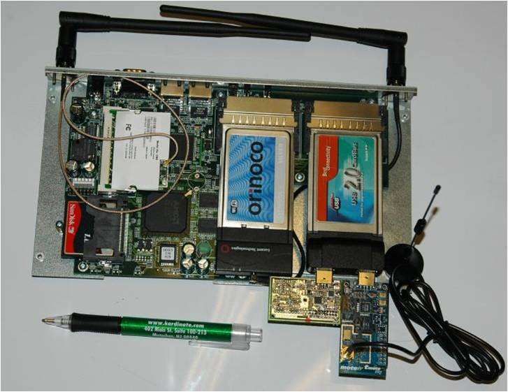
4Figure 2: A GRAIL landmark that simultaneously monitors packets from WiFi, ZigBee, and Roll-Call.
of network bandwidth, the resulting compatibility gains are substantial. Using a binary or XML-based protocol
would have forced us to develop additional software components, with little to no benefits, whereas the current
system is simple, extensible, and facilitates interchangeable components.
3 Landmark
The primary job of a landmark is to convert network- and device-specific observations into the low-level ab-
stractions. That is, landmarks passively observe the radio channel and report information, such as RSS, TOA,
AOA, and packet headers to the server, which has knowledge of the landmark’s location, for aggregation and
processing. GRAIL assumes the transmitter of a packet is identifiable via a unique ID. The current system uses
layer-2 addresses as a unique identifier. Landmarks are stateless, that is, landmarks do not hold any permanent
state needed for localization. Keeping the landmarks stateless greatly simplifies their design.
Typically, a landmark is implemented using off-the-shelf radio technologies that are placed in “monitor” or
“scanning” modes. These modes often forgo processing the layer-2 protocols, and simply pass all packets on
a given channel to the higher layer, along with metadata such as RSS and TOA. More sophisticated hardware
configurations can simultaneously pass copies of the packets to the landmark and act as a regular layer-2 device,
although these devices are the exception rather than the rule. If simultaneous monitoring and protocol operations
are possible, the landmark can act as both a landmark and a wireless access point.
A landmark can also support multiple radio technologies. Figure 2 shows a picture of a landmark that can
simultaneously capture 802.11, ZigBee and Roll-Call packets. The landmark software is divided into a device
dependent and device independent layers. The device-dependent layer handles sample creation and the indepen-
dent layer manages the samples.
A single-board 133 Mhz 486 computer running Linux hosts the different radio technologies, demonstrating
that the landmarks can operate effectively with little processing power compared to the other system components.
Landmarks can support different physical layers and report to which physical layer each network ID belongs.
Landmarks currently support two methods of reporting the observed data back to the server: per-packet or
aggregated.
• Per-packet samples are used when the landmark has a higher-bandwidth connection to the server than the
wireless channels from which it is collecting data. For example an 802.11 listener with a 100 Mbps wired
connection, or a Roll-Call listener with an 11 Mbps 802.11b connection to the server can send per-packet
samples. Using this method of reporting, a sample is a packet summary, e.g., the network ID and RSS of
a packet, followed by the first N bytes (typically 256) of the packet header.
• Aggregate samples send a summary of a series of packets for each network transmitter. The current
protocol enables landmarks to send per-layer-2 ID histograms of RSS values measured over the last k
seconds. That is, the landmark sends the set of value/count pairs it received over the last k seconds.
In both cases, the landmarks need to perform some interpretation of the packet headers. As a minimum,
the landmark must extract the layer-2 address of the transmitter and the RSS value from the packet header.
Additional information is optional, but can be utilized by the server if available.
5Characteristics
The server acts as a central point of coordination in the GRAIL system. It interacts with all the other system
components, and its main characteristics include:
• Soft State: The server maintains a soft state, keeping only the most recently-collected data internally, and
storing the rest of the data, including landmark information, localization results, and transmitter details,
in the database. This allows the server to restart without adversely affecting the localization system. After
a server restart, landmarks and solvers automatically reconnect, and landmarks resume sending samples.
In order to support localization on past data, the server sends fingerprints to the database, where they can
be recalled later to enable further data analysis. Raw packet headers can also be stored, although we do
not use this feature for normal localization.
• Authentication: The current implementation provides simple authentication using named accounts and
clear-text passwords. Landmarks and solvers must be programmed with the correct usernames and pass-
words in order to connect to the server. Further access restrictions can be implemented using IP address
filtering to allow only the web server, landmarks, and solvers to connect to the server. Given that GRAIL’s
external interface is through the web server, and the server is behind the organization’s firewall to the
external world, we view this level of security as sufficient.
• Supporting Data Abstraction: The server is centered around the high-level data abstractions including
regions, landmarks, transmitters, samples, fingerprints, training data, testing data, and locations. The
server manages multiple regions, each region being independent of the others, though not necessarily
disjoint, and potentially representing the same physical location. Each region keeps track of the landmarks
and transmitters located within its boundaries. Within the server, transmitters are identified by their layer-
2 addresses, and as samples are collected by landmarks for each transmitter, fingerprints can be generated
for use in localization.
• Decoupled Operation: Decoupling the server and solvers, i.e., having them run as separate processes or
on separate hosts, has several advantages. It allows seamless integration of any new solver implementa-
tions into the GRAIL framework. The server can launch multiple solver instances under periods of high
load, for example if it needs to simultaneously localize hundreds of transmitters. Decoupling also makes
it easier to scale the hardware and software resources dedicated to running the localization algorithm. For
example, a parallel machine could be dedicated to running a parallelized solver, leaving a machine with a
slower processor to handle the coordination tasks of the server.
The disadvantage of the decoupled approach is that it increases localization latency because messages
must be exchanged between processes, or possibly even over a network, in order to localize. However,
we have found that the advantages of decoupling the server and solvers outweigh the cost of increased
latency.
• Privacy Mechanisms: The centralized server entity makes enforcing contracts and privacy policies
more tractable. Currently, the only privacy mechanisms that are supported in GRAIL are positive and
negative filters on network addresses. Positive filters describe network transmitters which are allowed to
be localized, while negative filters describe transmitters to be discarded. The filters can be applied in two
places: a)when data arrives from a landmark, and b) just before data is sent to a solver. Filering in the latter
approach allows the system to retain observations for network devices, even if immediate localization of
these devices is not desired.
Localization Process
The server controls when localization occurs, and it can be manual or automatic. A manual localization is
performed at the request of a user through the web-based GUI on the web server. Automatic localization can be
further refined into 3 subcategories: time-based, fingerprint-based, and sample-based.
6(a) Non-hierarchical Bayesian graphical model (b) Hierarchical Bayesian graphical model
Figure 3: Bayesian networks used in the solver component.
Time-based localization is the most common trigger. It takes place when a timer with a predefined wait
period expires, and can ensure that a localization takes place every n seconds. Fingerprint-based localization
takes place whenever the computed fingerprints for a transmitter exceed a predefined threshold, and allows the
server to localize moving transmitters more often than stationary devices. Further, a sample-based localization
occurs when a predefined number of samples is received for a transmitter. This enables the server to localize
a transmitter after every k samples have been received, and allows the system to track transmitters generating
more network traffic more closely than those that generate less traffic.
5 Solver
Supporting Different Algorithms
The major role of the solver component is to perform position estimation utilizing information sent from the
server. The solver is flexible, scales easily, and can support multiple localization algorithms. The solver has
two layers as shown in Figure 4. The top layer interfaces with the server and handles communication and
protocol-related information. The bottom layer is where the different localization algorithms are plugged in, and
is independent of the communication protocols and the external interface.
The current GRAIL system supports two solvers that utilize Bayesian networks for localization: the WinBugs
Solver and the Fast Solver. The WinBugs Solver uses the statistical WinBugs tool [6]. WinBugs is a general
purpose comprehensive Bayesian analysis tool for solving complex statistical models using Markov chain Monte
Carlo (MCMC) methods. It usually encounters high computational cost since it does not account for any special
properties of wireless networks. As a result, we were motivated to develop our own customized Bayesian
solvers, the Fast Solver [7]. It achieves computational efficiency and simultaneously provides good ratio of
accuracy vs. time. The Fast Solver uses a novel real-time sampling technique which reduces the computational
cost significantly and solves Bayesian networks 9 to 17 times faster than the WinBugs Solver. It localizes 1 to 10
transmitters in less than half a second, and scales to 50 transmitters simultaneously, with no location information
in the training data, within 6 seconds.
Although the current GRAIL system only supports Bayesian networks, its distributed and scalable architecture
is designed for maximum flexibility. Solvers that implement other localization algorithms such as RADAR
[8], Simple Point Matching (SPM), and Area Based Probability (ABP) [5], can be easily integrated into the
system with no architecture changes. As shown in Figure 4, WinBugs Solver, Fast Solver, RADAR Solver, SPM
Solver, and ABP Solver can coexist within the solver system component. During real time localization, different
localization algorithms can be used by the server, either specified in each user request, or from an internal default
setting.
Bayesian Modeling
7Figure 4: Layered architecture in solver.
Figure 5: Communication between the server and a solver.
The Bayesian network is a graphical model that encodes dependencies and relationships among a set of random
variables. The vertices of the graph correspond to the random variables and the edges represent dependencies.
Bayesian inference in conjunction with Bayesian networks offers an efficient and principal approach for avoiding
the over-fitting of data.
In the GRAIL system, we developed several Bayesian graphical models to encode the relationship between
the RSS and the location based on signal-to-distance propagation model. We have built both non-hierarchical
(M1), as well as hierarchical (M2) Bayesian graphical models as displayed in Figure 3 (a) and (b). Both M1 and
M2 need to use the training data to predict the parameters in Bayesian networks and inference the (x, y) location
of the transmitter. Moreover, we introduced a special model [9] which provides a zero-profiling approach for
location estimation and aims to significantly reduce the labor-intensive training step.
Communication Interface
The server and solvers communicate using a simple text-based protocol over TCP sockets. In order to perform
localization, the server needs to send the following information to the solver, as shown in Figure 5:
• Landmark positions: Positions of a set of landmarks in the region of interest.
• Training data: The training data consists of the fingerprints collected at known locations along with their
coordinates, similar to a signal map of the region. The training data is either collected off-line, generated
from stationary transmitters, or constructed from previous localization results. It can be retrieved from
the database or from files stored on the server. This way both on-line algorithms and those that require
off-line site surveys are supported.
• Testing data: The testing data is a list of fingerprints for the unknown wireless devices that need to
be localized, marked by their layer-2 addresses. The list can include all observed transmitters or only a
subset.
• Requested Return Type: The localization request can specify one of the following types of results:
points, ellipses, or tiles. If a basic localization algorithm only supports areas (e.g., ellipses or tiles), it
is the solver’s responsibility to transform these results into a simpler format if requested. For example,
selecting the tile with median X- and Y-coordinate is a simple method of converting a tile-based result to
a point-based one. This is consistent with the principle of having most of the algorithmic computation in
the solver and using the server only for coordination and control.
6 Database
The database holds the hard state of the system, and is in charge of maintaining all data that must survive a crash
and recovery. Specifically, it stores location information for transmitters, the fingerprints used to generate that
8Region (region-id, region-name)
Landmarks (device-id, name, region-id, x, y, z)
Transmitters (device-id, type, description)
Packets (device-id, t-stamp-msec, rssi, channel, protocol, deviceType, header)
Histograms (device-id, start-stamp, end-stamp, rssi, count)
Fingerprints (device-id, lm-id, region-id, start-stamp, end-stamp, rssi)
Loc-ellipses (device-id, region-id, start-stamp, end-stamp, x, y, z, plusminusx, plusminusy, plusminusz)
Loc-tiles (device-id, region-id, start-stamp, end-stamp, cellsize, cells)
Table 1: GRAIL database Schema; primary Keys are underlined
location information, and the landmarks associated with each RSS value of a fingerprint. Our implementation
uses the postgreSQL database.
Schema Description
Table 1 presents the database schema that implements our abstract data model. The table columns follow natu-
rally from the abstractions described in Section 2.
The Regions table stores the regions defined by the system. A region’s unique identifier and human-readable
name are stored in the region-id and region-name columns, respectively.
The Landmarks table stores the landmarks used by the system, and the regions in which they are defined. A
landmark’s unique identifier (e.g., layer-2 address), description of its position in physical space, defining region,
and X-, Y-, and Z-coordinates within the region are stored in the device-id, name, region-id, x, y, and
z columns, respectively.
The Transmitters table stores all the transmitters scanned in the environment. A transmitter’s unique identi-
fier (e.g., layer-2 address), type (e.g., stationary or mobile), and human-readable description are stored in the
device-id, type, and description columns, respectively. The description column can be used to de-
scribe the position of the transmitter, or could contain information regarding any special characteristics that the
device may have.
The Packets table stores information about all packets forwarded by the landmarks while performing trace
operations, and can be used for offline analysis. A packet is represented as a transmitter ID, timestamp, observed
RSS value, radio frequency channel, link-layer protocol, device type (e.g., 802.11), and the first n bytes of the
packet header. These values are stored in the device-id, t-stamp-msec, rssi, channel, protocol,
deviceType, and header columns, respectively.
Similar to the Packets table, the Histograms table stores information about aggregated packet data, as described
in Section 3. Histograms are represented by a transmitter ID, beginning and ending timestamps, RSSI value,
and the number of packets observed with that RSSI value, and are stored in the device-id, start-stamp,
end-stamp, rssi, and count columns, respectively.
The Fingerprints table stores the computed RSS samples, in the rssi column, for each transmitter-landmark
pair, identified by the device-id and lm-id, respectively. The start-stamp and end-stamp columns
denote the timestamps of the oldest and youngest packets used to generate the fingerprint, respectively.
The Loc-ellipses and Loc-tiles tables are used for storing ellipse-based and tile-based locations, respectively. A
location is linked to a network transmitter within a region by the device-id and region-id columnns, re-
spectively. The start-stamp and end-stamp columns represent the time stamps of the oldest and youngest
packets used to generate the localization result, respectively. For ellipse-based locations, the center of the ellipse
is stored as a 3-tuple of the X-, Y-, and Z-coordinates in the x, y, and z columns, and the columns plusminusx,
plusminusy, and plusminusz represent the uncertainty range for each dimension. Points are represented
as ellipses with uncertainty values of 0. A tile-based location is represented by the length of the side of a tile,
and a list of tiles containing the possible position of the device, which are stored in the cellsize and cells
columns, respectively.
Retrieving Tracks
The database and the web server components are directly linked together, as shown in Figure 1, which allows
the web server to issue simple SQL statements in order to retrieve location data for presentation to the user.
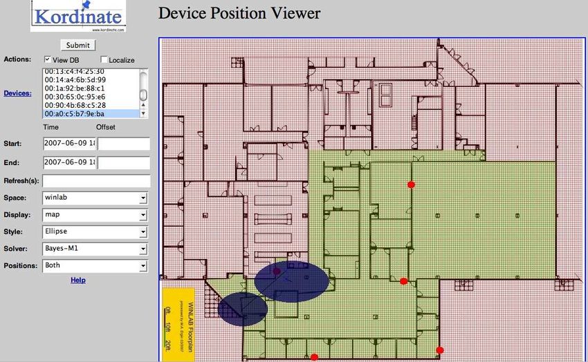
9Figure 6: A screen shot of GRAIL web-based GUI: the left side contains parameters related to localization, and
the right side is a graphical depiction of a research laboratory being used for localization.
Displaying device tracks, the estimated locations of a device over some finite range of time, is easily performed
by making simple SQL queries on the database’s Loc-ellipses and Loc-tiles tables.
It is important to note that a wide range of more complex queries can made on the current localization database
in order to extract additional information. For example, a network administrator can compose queries to monitor
the coverage map of landmarks on a floor or locate a troublesome device that is utilizing a high percentage of
network bandwidth. This would involve only a few extra queries on the Fingerprints and Landmarks table. In
a similar fashion, a whole suite of applications could be built on top of the core tracking functions provided by
the GRAIL system.
7 Web Server
The Apache web server is used as GRAIL’s external interface. Using a web interface has the key advantages that
any client can connect to the service. Clients could be either humans browsing web pages, or programs calling
HTTP methods to extract the data. The programming interface outputs data as comma-separated value (CSV)
files, while the human interface methods output both CSV and displays the results graphically.
Using a web server as the system interface also allows GRAIL to leverage the web’s existing security and
authentication methods, for example, directories and methods accessed only through secure HTTP. The current
system provides a simple username/password structure to access the entire dataset. More sophisticated mappings
of users to views of system data remains as future work.
The web-based GUI is a part of the web server and comprised of two parts: displaying location data and
controlling the localization parameters. Figure 6 displays an example session using our GUI, where the left side
of the screen depicts the configurable system parameters, and the right side is a graphical representation of a
region, a research laboratory, being used for localization. The shadowed ellipses are the estimated positions of
two transmitters.
The localization control interface allows users to specify localization parameters in terms of changes in time,
RSS, or number of samples, and allows a user to initiate a localization by hand. The current interface does
not allow the end users to control the landmarks or the core server functionality. We conjecture this low-level
administration and configuration is best left to the system administrators.
10We deployed the GRAIL system in a few office building envorinments including the Computer Science Depart-
ment at Rutgers University, the Wireless Information Network Laboratory (WINLAB) at Rutgers University, the
Computer Science Department at Lafayette College, as well as in exhibit halls as part of conferences and trade
shows.
We found that the issues that concerned us the most were in the areas of security, privacy, and localization
performance:
• Security: Our initial assumption that all systems behind the webserver would be in a ’flat’ IP address
space was incorrect. Rather, in a typical deployment the landmarks are behind network address translation
(NAT) boxes. We found that, from the system security point of view, our approach of using a centralized
server has major advantages over distributed or hop-by-hop implementations because the server is the
only component that needs a visible IP address to the other components. This makes our system more
deployable because the other system components can be placed behind NAT firewalls, which is quite
common in real environments.
• Privacy: The main question that people asked about our localization system is what should constitute
"fair use" of the localization results? The challenge of privacy in wireless localization is sharing the right
information with the right people. A suite of access control policies can be developed towards this end. In
GRAIL, currrently we use a simple approach to only restrict the access of data to the authorized network
administrators.
• Localization performance: Signal coverage can be a significant issue during deployment. We found that
landmark placement is critical for achieving good localization performance [10]. Another key challenge
we found is that the localization algorithms need to be robust to missing data. They should produce a
reasonable location estimation even when only one landmark sees a packet, e.g., a circle around a single
landmark is better than no estimate. Finally, we found that it is easy to incorporate new radio technology
into GRAIL. For instance, incorporating Roll-Call into GRAIL took only two days.
9 Related Systems
Indoor localization has attracted an immense volume of research since the introduction of pervasive computing.
Although it is impossible to cover this broad base of work here, the majority of these works have focused on
algorithms and modalities, as opposed to general purpose frameworks.
Many different modalities have been investigated, including received signal strength (RSS) [8, 11], Time-
Of-Arrival (TOA) [12], and Angle-Of-Arrival (AOA) [13, 14]). Algorithmic work also spans a wide range,
including basic matching [8], probabilistic approaches [11], and machine learning algorithms such as Bayesian
networks [15] and neural networks [16]. These works typically focus on the algorithms’ localization accuracy
and computational costs. Typically, these works conducted off-line experiments using data collected off-line
rather than being implemented as part of a running system. Although such proposed algorithms can be easily
integrated into our GRAIL system as solver modules, they are not directly related to the design of our GRAIL
system. Instead, in the rest of this section we compare GRAIL to a few running indoor localization systems.
Ekahau [17] is a commercialized localization system using WiFi (802.11) networks. The system bootstraps
by site surveying the targeted building and localization is thus achieved through comparison of the RSS set from
the mobile device with the survey data. The key architectural difference with GRAIL is that Ekahau is client-
based, while GRAIL is infrastructure-based. That is, while Ekahau does not deploy additional landmarks or
base-stations, it needs software components to be installed on the WiFi devices to be localized. Our experience
has been that installing extra landmarks is easier and cheaper when the organization controlling the infrastructure
wants to provide a localization service. On the other hand, if users want to localize their devices and do not have
the support of the organization, client-based solutions are better. The value of a client or infrastructure system
11and responsibility over devices: administrators control the radio channel but users control their devices.
Ekahau’s system also requires that a site survey be performed by a mobile device during the deployment, and
whenever the radio environment changes. We found performing site surveys tedious, error prone, and that they
needed to be repeated every few months. For this reason GRAIL is built to allow continuous monitoring as well
as support algorithms that do not require a site survey. Finally, Ekahau only supports 802.11 radio type, while
GRAIL is designed to support any packet-based radio networks, such as ZigBee and Roll-Call networks.
Cricket [12] and Active Bat [18] systems use both RF radio and ultrasound. The localization is performed
through TOA and trilateration. We can build ultrasound sniffers and directly integrate the Active Bat system into
our GRAIL infrastructure. The Cricket system can be similarly adopted if we reverse the role of transmitters
and receivers from its original design. However, we will not be able to keep the privacy feature after adaption,
i.e., location information is not only available to the particular device being localized.
LEASE [19] system has a very similar data acquisition component as GRAIL. It uses sniffers to scan the WiFi
channels, which are equivalent to our landmarks. It also uses Stationary Emitters (SE) with known locations
to continously sample the environment. This feature is readily supported in GRAIL. GRAIL offers much more
than LEASE because it contains the additional server, solver, and database modules to enable a more general
purpose and flexible system, as opposed to supporting only a single algorithm.
Place Lab [20] works both indoors and outdoors and focuses on improving the coverage of localization ser-
vices in general. In the running system, to automate the localization step, each mobile device will also need to
install specific software to query beacon location databases. Place Lab demonstrated an achieved median error
of 20-30 meters [20]. This is usually unacceptable for indoor applications. However, we may use Place Lab as
an intermediate step to cover the outdoor areas between buildings equipped with GRAIL, similar to BGP versus
RIP. Such a combination can help us easily achieve high coverage and scalability.
Finally, many outdoor localization systems such as GPS do not work indoors and are thus not comparable
to GRAIL. Similar to Place Lab, they can also be used to integrate buildings equipped with GRAIL. However,
additional hardware may be needed to accomodate GPS integration.
10 Conclusions
In this work, we present GRAIL, a general purpose localization sytem. The main objective of GRAIL is to
position arbitrary wireless transmitting devices in an indoor environment. The current system can position
802.11, 802.15.4 and Roll-Call devices. In contrast to a specialized localization system, GRAIL is designed
to support multiple physical modalities and a diverse set of localization algorithms. A key contribution of this
system is its universal approach: it can integrate different hardware and software capabilities within a single
localization framework.
Moreover, we found that a centralized solution has critical advantages that are often overlooked in the litera-
ture. First, it makes cleaning and summarizing the traffic observations much easier. Second, it enables a variety
of additional services, such as attack detection and tracking, to utilize the same underlying localization system.
Finally, we believe that centralization makes enforcing contracts and privacy policies tractable. However, we
will leave open the issues of privacy contracts and policy enforcement as future work.
The deployment of such a system in academic and research environments will allow researchers to explore
issues beyond algorithms and simulation tools. It would make it possible to conduct higher-level integrated
research investigation including privacy studies, security services, and policy enforcement. For instance, we
utilized the GRAIL system to conduct research on detecting and localizing identity-based spoofing attacks in
wireless networks [21]. Further, the practical usage of such an approach is significant because it can be applied
to a broad array of applications such as monitoring, tracking, routing, and security services.
12[1] “The GRAIL Real Time Location Service,” documentation and source code is available at
http://grailrtls.sourceforge.net.
[2] “IEEE 802.11 Standards,” http://standards.ieee.org/getieee802/802.11.html.
[3] “IEEE 802.15.4 Standards,” http://standards.ieee.org/getieee802/download/802.15.4-2003.pdf.
[4] “Inpoint Systems,” white paper available at http://inpointsys.com.
[5] E. Elnahrawy, X. Li, and R. P. Martin, “The limits of localization using signal strength: A comparative
study,” in Proceedings of the First IEEE International Conference on Sensor and Ad hoc Communcations
and Networks (SECON 2004), Oct. 2004, pp. 406–414.
[6] “The BUGS Project,” white paper available at http://www.mrc-bsu.cam.ac.uk/bugs/.
[7] K. Kleisouris and R. P. Martin, “Reducing the computational cost of bayesian indoor positioning systems,”
in Proceedings of the Third IEEE International Conference on Sensor and Ad hoc Communcations and
Networks (SECON 2006), September 2006.
[8] P. Bahl and V. N. Padmanabhan, “Radar: An in-building rf-based user location and tracking system,” in
Proceedings of the IEEE International Conference on Computer Communications (INFOCOM), March
2000, pp. 775–784.
[9] D. Madigan, E. Elnahrawy, R. Martin, W. Ju, P. Krishnan, and A. S. Krishnakumar, “Bayesian indoor
positioning systems,” in Proceedings of the IEEE International Conference on Computer Communications
(INFOCOM), March 2005, pp. 324–331.
[10] Y. Chen, J. Francisco, W. Trappe, and R. P. Martin, “A practical approach to landmark deployment for
indoor localization,” in Proceedings of the Third Annual IEEE Communications Society Conference on
Sensor, Mesh and Ad Hoc Communications and Networks (SECON), September 2006.
[11] S. Thrun, W. Burgard, and D. Fox, “A probabilistic approach to concurrent mapping and localization
for mobile robots,” Machine Learning, vol. 31, no. 1-3, pp. 29–53, 1998. [Online]. Available:
citeseer.ist.psu.edu/thrun98probabilistic.html
[12] N. Priyantha, A. Chakraborty, and H. Balakrishnan, “The cricket location-support system,” in Proceedings
of the ACM International Conference on Mobile Computing and Networking (MobiCom), Aug 2000, pp.
32–43.
[13] D. Niculescu and B. Nath, “Vor base stations for indoor 802.11 positioning,” in in Proceedings of the
Annual ACM International Conference on Mobile Computing and Networking (MOBICOM), 2004, pp.
2926–2931.
[14] E. Elnahrawy, J. Austin-Francisco, and R. P. Martin, “Adding angle of arrival modality to basic rss loca-
tion management techniques,” in IEEE International Symposium on Wireless Pervasive Computing (ISW-
PCÕ07), Puerto Rico, Feb. 2007.
[15] D. Madigan, E. Elnahrawy, R. P. Martin, W.-H. Ju, P. Krishnan, and A. S. Krishnakumar, “Bayesian indoor
positioning systems,” in The 24rd Annual Joint Conference of the IEEE Computer and Communications
Societies (INFOCOM’05), Miami,FL, Mar. 2005.
[16] R. Battiti, M. Brunato, and A. Villani, “Statistical Learning Theory for Location Fingerprinting in Wireless
LANs,” University of Trento, Informatica e Telecomunicazioni, Technical Report DIT-02-086, Oct. 2002.
13http://www.ekahau.com.
[18] A. Ward, A. Jones, and A. Hopper, “A new location technique for the active office,” 1997. [Online].
Available: citeseer.ist.psu.edu/ward97new.html
[19] P. Krishnan, A. S. Krishnakumar, W. Ju, C. Mallows, and S. Ganu, “A system for lease: Location estimation
assisted by stationary emitters for indoor rf wireless networks,” in Proceedings of the IEEE International
Conference on Computer Communications (INFOCOM), Oct 2004.
[20] A. LaMarca, Y. Chawathe, S. Consolvo, J. Hightower, I. Smith, J. Scott, T. Sohn, J. Howard, J. Hughes,
F. Potter, J. Tabert, P. Powledge, G. Borriello, and B. Schilit, “Place lab: Device positioning using radio
beacons in the wild,” in Proceedings of the 3rd International Conference on Pervasive Computing (Perva-
sive 2005), May 2005.
[21] Y. Chen, W. Trappe, and R. P. Martin, “Detecting and localizing wireless spoofing attacks,” in Proceedings
of the Third Annual IEEE Communications Society Conference on Sensor, Mesh and Ad Hoc Communica-
tions and Networks (SECON), May 2007.
14You can also read