Heater Integrated Lab-on-a-Chip Device for Rapid HLA Alleles Amplification towards Prevention of Drug Hypersensitivity
←
→
Page content transcription
If your browser does not render page correctly, please read the page content below
sensors
Article
Heater Integrated Lab-on-a-Chip Device for Rapid HLA Alleles
Amplification towards Prevention of Drug Hypersensitivity
Shah Mukim Uddin 1 , Abkar Sayad 2 , Jianxiong Chan 1,2 , Duc Hau Huynh 1 , Efstratios Skafidas 1,3
and Patrick Kwan 1,2,3, *

                                          1   Department of Medicine, The University of Melbourne, Royal Melbourne Hospital,
                                              Melbourne, VIC 3050, Australia; suddin1@student.unimelb.edu.au (S.M.U.);
                                              jianxiong.chan@monash.edu (J.C.); duchau.huynh@gmail.com (D.H.H.); sskaf@unimelb.edu.au (E.S.)
                                          2   Department of Neuroscience, Central Clinical School, Monash University, Melbourne, VIC 3004, Australia;
                                              abkar.sayad@monash.edu
                                          3   Department of Electrical and Electronic Engineering, Melbourne School of Engineering,
                                              The University of Melbourne, Melbourne, VIC 3010, Australia
                                          *   Correspondence: patrick.kwan@monash.edu

                                          Abstract: HLA-B*15:02 screening before administering carbamazepine is recommended to prevent
                                          life-threatening hypersensitivity. However, the unavailability of a point-of-care device impedes this
                                          screening process. Our research group previously developed a two-step HLA-B*15:02 detection
                                          technique utilizing loop-mediated isothermal amplification (LAMP) on the tube, which requires
                                          two-stage device development to translate into a portable platform. Here, we report a heater-
                                integrated lab-on-a-chip device for the LAMP amplification, which can rapidly detect HLA-B alleles

                                          colorimetrically. A gold-patterned micro-sized heater was integrated into a 3D-printed chip, allowing
Citation: Uddin, S.M.; Sayad, A.;
                                          microfluidic pumping, valving, and incubation. The performance of the chip was tested with color
Chan, J.; Huynh, D.H.; Skafidas, E.;
                                          dye. Then LAMP assay was conducted with human genomic DNA samples of known HLA-B
Kwan, P. Heater Integrated
                                          genotypes in the LAMP-chip parallel with the tube assay. The LAMP-on-chip results showed a
Lab-on-a-Chip Device for Rapid HLA
                                          complete match with the LAMP-on-tube assay, demonstrating the detection system’s concurrence.
Alleles Amplification towards
Prevention of Drug Hypersensitivity.
Sensors 2021, 21, 3413. https://
                                          Keywords: loop-mediated isothermal amplification; microfluidics; lab-on-a-chip; point-of-care diag-
doi.org/10.3390/s21103413                 nostics; pharmaco-genetics

Academic Editor: Nicole
Jaffrezic-Renault
                                          1. Introduction
Received: 24 March 2021                        Aromatic ring structured antiepileptic drugs (AEDs) such as phenytoin (PHT), lamot-
Accepted: 10 May 2021
                                          rigine (LTG), and carbamazepine (CBZ) are the most prevalent sources of severe cutaneous
Published: 13 May 2021
                                          adverse drug reactions [1,2]. These range from benign to severe reactions, including drug
                                          reactions with eosinophilia, systemic symptoms (DRESS), acute generalized exanthema-
Publisher’s Note: MDPI stays neutral
                                          tous pustulosis (AGEP), toxic epidermal necrolysis (TEN), and Stevens–Johnson syndrome
with regard to jurisdictional claims in
                                          (SJS) [3,4]. The incidence estimation of SJS/TEN ranges from 1 in 1000 to 10,000 drug
published maps and institutional affil-
                                          exposures [5,6], and its mortality rate is as high as 35% [7,8]. Pharmacogenetic studies
iations.
                                          have discovered genetic associations between antiepileptic drugs-induced cutaneous ad-
                                          verse drug reactions and the human leukocyte antigen (HLA) alleles. Carbamazepine is
                                          an iminodibenzyl derivative that is extensively used in treating epilepsy and other indi-
                                          cations such as neuralgia and bipolar affective disorder. Specifically, SJS/TEN induced
Copyright: © 2021 by the authors.         by carbamazepine is strongly associated with HLA-B*15:02 in broad Asian ethnicities,
Licensee MDPI, Basel, Switzerland.
                                          including the Han Chinese and Thai population [9–12], but not in the Japanese [13] and
This article is an open access article
                                          European population [14]. Pre-treatment HLA genotyping is recommended to prevent car-
distributed under the terms and
                                          bamazepine induced SJS/TEN. However, several challenging factors need to be considered
conditions of the Creative Commons
                                          in the implementation of this recommendation [15].
Attribution (CC BY) license (https://
                                               Conventional methods to type HLA-B*15:02 include commercial polymerase chain
creativecommons.org/licenses/by/
                                          reaction (PCR) with sequence-specific oligonucleotides (SSOP) or sequence-specific primer
4.0/).

Sensors 2021, 21, 3413. https://doi.org/10.3390/s21103413                                                   https://www.mdpi.com/journal/sensors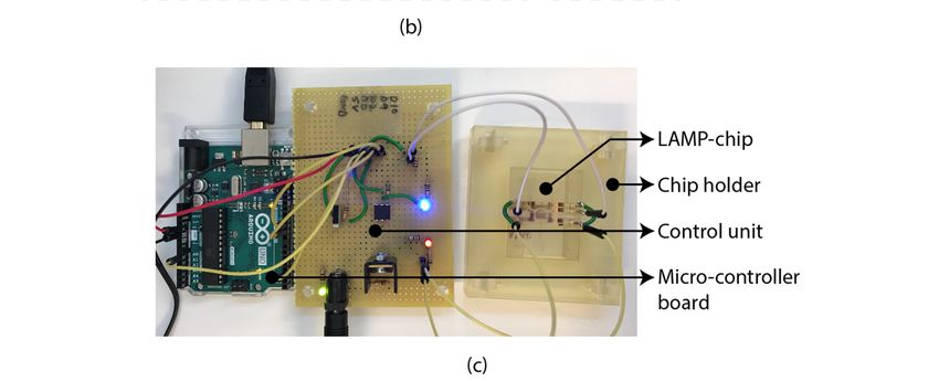
Sensors 2021, 21, 3413                                                                                           2 of 14

                         (SSP) [16], and sequence-based typing (SBT) [17]. These methods require expensive labora-
                         tory equipment, skilled laboratory personnel, and extensive processing time. Consequently,
                         current methods pose barriers for prompt drug administration during or post-seizure,
                         where prompt HLA-B*15:02 genotyping is necessary [18]. To overcome these barriers, our
                         research group is developing a miniaturized point-of-care device for rapid genotyping of
                         HLA-B*15:02. Crude blood samples were previously used in loop-mediated isothermal
                         amplification (LAMP) reaction, which selectively amplifies selected areas in the HLA-B
                         alleles. Afterward, the LAMP amplicon hybridizes with the DNA probes immobilized
                         on the interdigitated electrode (IDE)-based biosensor surface that act as the mono-allelic
                         determinant of an HLA-B*15:02 LAMP amplicon [19]. The probe hybridization process to
                         complementary HLA-B*15:02 LAMP amplicons alters the biosensor’s electrical impedance
                         to provide qualitative results.
                               Microfluidic devices are a basic element to develop the micro-total analysis systems
                         (µTAS) or lab-on-a-chip device. These systems are classified as mechanical and non-
                         mechanical based on the structure [20]. These systems are also classified as active or
                         passive devices based on fluid flow techniques [21,22]. Active microfluidics [23,24] involve
                         the motion or transportation of the biological samples applying an external source [25–27]
                         or actuators [28]. On the other hand, the device’s physical configuration defines the sys-
                         tem’s functionality in passive microfluidics. This device operates by the working fluid’s
                         surface effects, such as surface tension, osmosis, pressure, capillary action, gravity-driven
                         flow, vacuums, hydrostatic flow, and selective hydrophobic/hydrophilic control [29]. The
                         structural complexity of the passive devices is relatively higher compared to the active
                         device. Hence, the integration of passive microfluidics is challenging in point-of-care appli-
                         cations [30]. Microvalves and micro-pumps are the foundation of microfluidic systems.
                               Microvalves allow the regulation of liquid flow in a micro-channel by varying a
                         macroscopic parameter or actuator. Microvalves’ functions include on-off switching, flow
                         regulation, flow routing, fluid separation, and sealing biomolecule/particles in the incuba-
                         tion chamber. Such microvalves need to fulfill several requirements to integrate the DNA
                         amplification process. Firstly, the valves need to withhold the pressure produced through-
                         out the incubation period because of the sample evaporation and air expansion at high
                         temperature. The valve needs to ensure the amplified sample’s confinement inside the reac-
                         tion chamber without leakage flow during amplification. Secondly, the valve material needs
                         to be chemically resilient because the valves will contact the LAMP solution. Multiple re-
                         search groups have reviewed the range of valves with different working principles [31–35].
                         Among the valve’s variants, mechanical active microvalves are easier to develop and
                         require less complicated microfluidic design. Mechanical active valves are designed uti-
                         lizing the Bio-MEMS-based surface micromachining technologies, where mechanically
                         movable membranes are coupled to magnetic, electric, thermal, and piezoelectric actuators.
                         The micropump function in the microfluidic device is to pressurize the working liquid
                         for flowing through the system. The fluid transport mechanism of the pressure-driven
                         microfluidic device is based on pressure gradients. The mechanical micropump usually
                         utilizes a physical actuator or moving parts such as oscillating membranes/diaphragm,
                         piston, or turbines for delivering a persistent fluid volume. Multiple research groups have
                         reviewed the micropump range with different working principles [25,28,31–33,36–41].
                               LAMP [42] technique operates at a constant temperature which reduces the require-
                         ments for the microfluidic feature. The typical operating temperature for LAMP is 60–65 ◦ C,
                         and the amplification time is 15–60 min. Hence, the LAMP device specification is rela-
                         tively simpler than standard PCR, making this technique a promising DNA amplification
                         alternative and ideal for point-of-care (POC) applications [43–45]. A critical step of the
                         LAMP chip development is the device material selection considering an adverse effect,
                         disposability, manufacturability, and cost-effectiveness. Different materials are utilized
                         for microfluidic device construction, such as glass [46], silicon [47], polydimethylsiloxane
                         (PDMS) [48–50], PMMA [51–53], polystyrene (PS) [54], polycarbonate (PC) [55], cyclic
                         olefin polymer (COP) [56], and cyclic olefin copolymer (COC) [57]. PDMS is one of the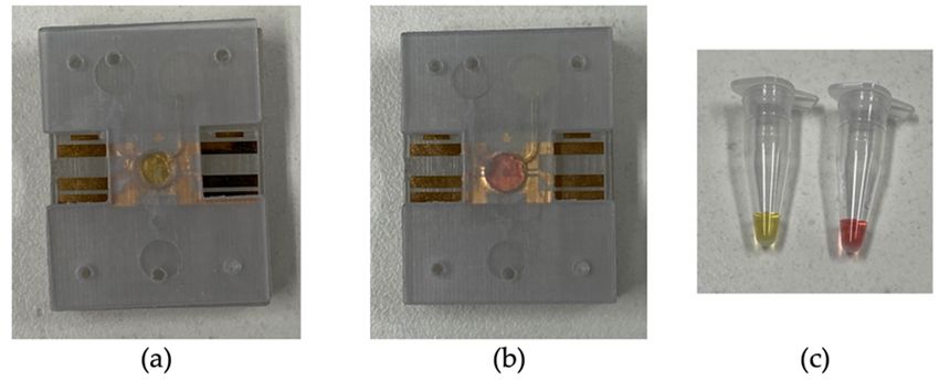
Sensors 2021, 21, 3413                                                                                       3 of 14

                         most preferred polymeric materials for rapid prototyping of microfluidic devices, but
                         it is expensive due to the photolithography requirement. Thermoplastic polymers such
                         as PMMA, PC, PS, COC, and COP are widely utilized due to their exceptional chemical
                         and physical properties. Glass is used due to its favorable optical and electrical proper-
                         ties. Silicon is used because of its good thermal conductivity, making it ideal for rapid
                         heating and cooling. Several review articles critically analyzed the advantages and draw-
                         backs of the currently developed microfluidic chips to apply the DNA amplification-based
                         diagnosis process [20,43,44,58–69]. Different aspects affect the performances of the mi-
                         crofluidic devices incorporating LAMP amplification. Some of them are related to the
                         assay’s miniaturization, others are related to the isothermal amplification methods. This
                         concern encourages the researchers to develop new microfluidic devices integrated with
                         simplified assays.
                               We previously developed a LAMP-IDE platform for HLA-B*15:02 genotyping, which
                         requires a two-step process [19]. Firstly, HLA-B alleles amplification is performed using
                         the LAMP technique on the tube. Secondly, LAMP amplicon hybridization on the de-
                         veloped biosensor surface occurs as a mono-allelic determinant of HLA-B*15:02. In that
                         study, LAMP was performed in a tabletop thermocycler, and the detection process was
                         performed with manual sample handling as a proof-of-concept. To transform this tabletop
                         platform into a portable platform, a 2-step POC device development is required. This will
                         require a microfluidic chip to perform the LAMP reaction and then integrate the previously
                         developed biosensor into the LAMP chip. Here, we describe a LAMP-on-a-chip device
                         integrating microfluidic operations and microheater towards developing a POC device for
                         precision medicine.

                         2. Materials and Methods
                         2.1. Samples and LAMP Reaction
                              Purified human genomic DNA samples of known HLA-B genotypes were used to
                         perform the LAMP reaction acquired from healthy donors (University of Melbourne ethics
                         committee, ethics ID 1443204.4). The LAMP primer set was acquired from the previous
                         study, which our research group designed to amplify the HLA-B gene exon 2 [19]. LAMP
                         reagent contains 1XWarmStart® Colorimetric LAMP Master Mix (New England Biolabs,
                         Ipswich, Massachusetts), 1.6 µM inner primers (FIP and BIP), and 0.2 µM forward and
                         reverse primers (F3 and B3). All primers utilized were desalted grade (Integrated DNA
                         Technologies, Coralville, USA). A template volume of 1 µL was added with a concentration
                         of 50 ng/µL in each reaction. A template of HLA-B*15:02/HLA B75 was used as a positive
                         control and HLA-B*08:01/HLA B8 as a negative control. The blank negative control was
                         the nuclease-free water. Each reaction was adjusted to a final volume of 12.5 µL using
                         nuclease-free water. LAMP was conducted at 65 ◦ C for 20 min utilizing a thermal cycler
                         (Bio-Rad, Hercules, California). The LAMP reagents and DNA template were mixed on
                         the tube before loading into the LAMP-chip. After the LAMP reaction, the positive control
                         changes to yellow from its original pink color, whereas the negative color is unchanged.

                         2.2. Micro-Valve Design
                              The diaphragm-based active microfluidic system utilizes a reciprocating membrane
                         actuated by a physical actuator to control the microfluidic operation. A latex membrane-
                         based microfluidic valve was designed using 3D-printed parts manually controlled by
                         the piston. The 3D-printed parts and the latex membrane were bonded using a pressure-
                         sensitive adhesive (PSA). Figure 1 depicts the schematic of the developed microfluidic
                         valve mechanism. At an open state, the valve piston rests on the latex membrane, allowing
                         the fluid to flow through the microchannel. At a closed sate, the valve piston is pushed
                         down to the microchannel by deforming the latex membrane, which blocks the fluid flow.
                         This valve’s mechanical structure allows the piston to unlock/lock the position at an
                         open/close state.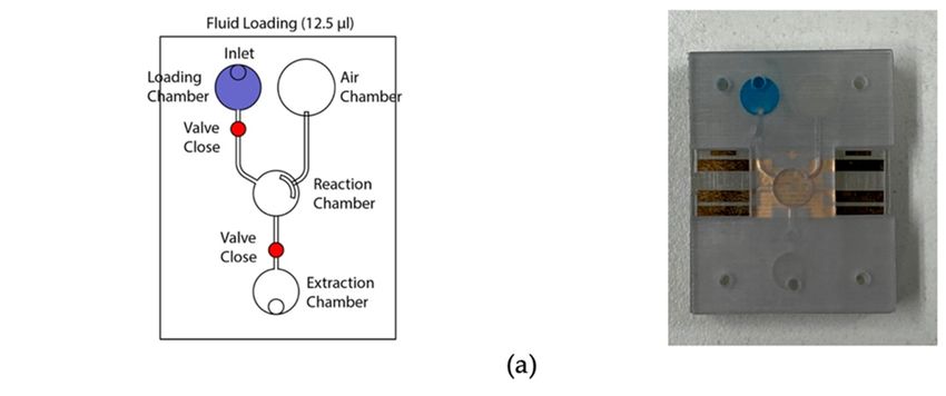
valve mechanism. At an open state, the valve piston rests on the latex membrane, allowing
the fluid to flow through the microchannel. At a closed sate, the valve piston is pushed
down to the microchannel by deforming the latex membrane, which blocks the fluid flow.
Sensors 2021, 21, 3413 4 of 14
This valve’s mechanical structure allows the piston to unlock/lock the position at an
open/close state.
Figure
Figure 1. Latex
1. Latex membrane-based
membrane-based micro-valve
micro-valve design
design in two in two
operating operating
states. states.
(a) Open state. The(a)piston
Open state.anticlock-
requires The
piston
wise requires
rotation ◦ anticlockwise
(90 ) and rotation
pulling to change (90°)
state from and
close pulling
to open; to change
(i) simplified state indicating
diagram from close theto open;
floated (i) on the
piston
simplified
latex membrane diagram
allowingindicating
the fluid to the
flow;floated piston
(ii) isometric onofthe
view thelatex
valvemembrane
indicating the allowing
handle forthe fluidcontrol;
manual to flow;(iii)
(ii) isometric
isometric view ofthethe
view indicating valve indicating
unlocked/pulled the handle
condition; for manual
(iv) isometric control;
view (isolated) (iii) isometric
indicating the collapsed viewcondition of
indicating
the piston. (b) the unlocked/pulled
Closed condition;
state. The piston requires (iv)and
pushing isometric
clockwise view
rotation (90◦ ) to change
(isolated) indicating the collapsed
state from open to close; (i)
simplified
condition diagram
of theindicating
piston. the
(b)piston
Closedblocked
state.theThe
microchannel deforming
piston requires the latexand
pushing membrane;
clockwise (ii) isometric
rotation view of the
(90°)
valve; (iii) isometric view indicating the locked/pushed condition; (iv) isometric
to change state from open to close; (i) simplified diagram indicating the piston blocked the view (isolated) indicating the expanded
condition
microchannelof the piston.
deforming the latex membrane; (ii) isometric view of the valve; (iii) isometric view
indicating the locked/pushed condition; (iv) isometric view (isolated) indicating the expanded
2.3. Micro-Pump Design
condition of the piston.
A diaphragm-based active microfluidic pump was designed using 3D-printed parts,
which were bonded using PSA. Reciprocation of the membrane in a mechanical micropump
2.3. Micro-Pump Design
occurs utilizing a physical actuator that generates the required pressure deviation to pump
the fluid.
A diaphragm-based Figure
active 2 depicts the
microfluidic schematic
pump of the developed
was designed microfluidic pump.
using 3D-printed parts, This
micro-pump utilizes a manually controlled piston placed on the air chamber, creating
which were bonded using PSA. Reciprocation of the membrane in a mechanical
positive/negative pressure into the sample chamber. Based on the Hagen–Poiseuille
micropump occurs equation,
utilizing theapressure
physical actuator
difference thatthe
between generates
two ends of the required
a channel is ∆p,pressure
deviation to pump the fluid. Figure 2 depicts the schematic of the developed microfluidic
8µLQ
pump. This micro-pump utilizes a manually controlled ∆p =piston placed on the air chamber,
πR4
creating positive/negative pressure into the sample chamber. Based on the Hagen–
Poiseuille equation,where L is the channel’s
the pressure length,
difference R is the
between thechannel’s
two ends radius, µ is the reagent’s
of a channel is Δp, dynamic
viscosity, and Q is the volumetric flow rate. Considering the flow rate was controlled
8
∆ =
where L is the channel’s length, R is the channel’s radius, μ is the reagent’s dynamic
viscosity, and Q is the volumetric flow rate. Considering the flow rate was controlled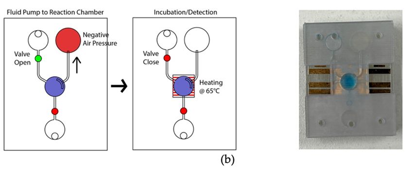
5 of 14
Sensors 2021, 21, 3413 5 of 14
manually by the finger-controlled piston, the channel’s dimension is constant, and the
pressure required to transport the fluid between C1 and C2 chamber is defined by the A1
manually by the finger-controlled piston, the channel’s dimension is constant, and the
chamber’s volume for the reagents.
pressure required toThe A1 chamber
transport volumeC1was
the fluid between andoptimized
C2 chamber to 2.5 times
is defined by the A1
of the fluidic chambers, experimentally.
chamber’s volume for theAt an idleThe
reagents. state, the piston
A1 chamber was
volume placed
was optimizedinside
to 2.5the
times of
air chamber (A1) by deforming the latex
the fluidic chambers, membrane where
experimentally. thestate,
At an idle fluidic is located
the piston in chamber
was placed inside the air
2 (C2), and chamberchamber
1 (C1) is(A1) by deforming
filled with air. the
Bylatex membrane
pulling wheredownward,
the piston the fluidic is located in chamber
a negative
2 (C2), and chamber 1 (C1) is filled with air. By pulling the piston downward, a negative
pressure is created in the A1 chamber, which leads to moving air from C1 to A1 and the
pressure is created in the A1 chamber, which leads to moving air from C1 to A1 and the
sample from C2 to C1. This from
sample stateC2is defined as astate
to C1. This pulling state.asThe
is defined pistonstate.
a pulling needs The topiston
be movedneeds to be
reversely to transport the reversely
moved liquid from C1 to C2.
to transport This from
the liquid stateC1istodefined
C2. This as a pushing
state is defined as state.
a pushing
This micro-pump’s mechanical structure allows the piston to lock the position in a in a
state. This micro-pump’s mechanical structure allows the piston to lock the position
pulling/pushing state.
pulling/pushing state.
Figure
Figure 2. 2. Latex
Latex membrane-based
membrane-based micro-pumpmicro-pump design
design in two in two
operating operating
states. states. (a)
(a) Ideal/pushing Ideal/pushing
state. The piston requires
state.
push Theand
action piston requiresrotation
anticlockwise push action
(90 ) toand
◦ anticlockwise
change the state fromrotation
pulled to (90°)
pushed; to (i)
change the diagram
simplified state fromindicating
pulled
the pistonto pushed;
placed inside(i)the
simplified
air chamberdiagram indicating
by deforming the latexthe piston placed
membrane. The chipinside the air chamber
was assembled in this stateby
which is
deforming
referred the‘ideal
to as an latexstate’;
membrane. Theview
(ii) isometric chipofwas assembled indicating
the micro-pump in this state the which
handle foris referred to as an
manual control; (iii) cross
‘idealalong
section state’;the(ii) isometric
x axis indicatingview of thecondition;
the locked micro-pump indicating
(iv) isometric the handle
view (isolated) for manual
indicating control;
the expanded (iii) of
condition
the piston. (b) Pulling state. The piston requires clockwise rotation (90 ◦ ) and pull action to change the state from pushed to
cross section along the x axis indicating the locked condition; (iv) isometric view (isolated)
pull; (i) simplified
indicating diagram indicating
the expanded condition the of
floated piston on(b)
the piston. thePulling
latex membrane;
state. The (ii)piston
isometric view of clockwise
requires the micro-pump;
(iii) cross section
rotation (90°) and the xaction
alongpull axis indicating
to change the the
locked condition;
state (iv) isometric
from pushed view
to pull; (i)(isolated) indicating
simplified diagram the collapsed
condition of the piston.
indicating the floated piston on the latex membrane; (ii) isometric view of the micro-pump; (iii)
cross section along the x axis indicating the locked condition; (iv) isometric view (isolated)
indicating the collapsed condition of the piston.
2.4. Micro-Heater Design
A resistive micro-heater was fabricated to integrate into the LAMP-chip. Figure 3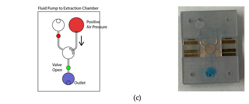
Sensors 2021, 21, 3413 6 of 14
Sensors 2021, 21, 3413 2.4. Micro-Heater Design
A resistive micro-heater was fabricated to integrate into the LAMP-chip. Figure 3
depicts the schematic and photograph of the fabricated heater and sensor. The micro-heater
has two sets of electrodes, (a) a heating electrode and (b) a temperature sensing electrode.
200heating
The μm, electrode
finger gap:
has 14 150 μm).
parallel The
fingers temperature
(finger length: 6 mm,sensing
finger width:electrode
200 µm, is a
finger gap: 150 µm). The temperature sensing electrode
zigzag pattern (length 70 mm, width 40 μm, and gap 40 μm).is a conductor line of zigzag pattern
These ele
(length 70 mm, width 40 µm, and gap 40 µm). These electrodes are made with multiple
with multiple
chemical chemical
elements (5nm Ti/100 nmelements
Au/5 nm (5nm
Ti/25 nmTi/100 nmfabrication
Si2 O). The Au/5 nm Ti/25was
process nm Si2O
process
reported in was
one ofreported
our previousinarticles
one of [19].our previous articles [19].
Figure
Figure 3. Photograph
3. Photograph and schematic
and schematic of the
of the integrated integrated
heater heatersensor
and temperature and on
temperature
a glass se
substrate.
substrate.
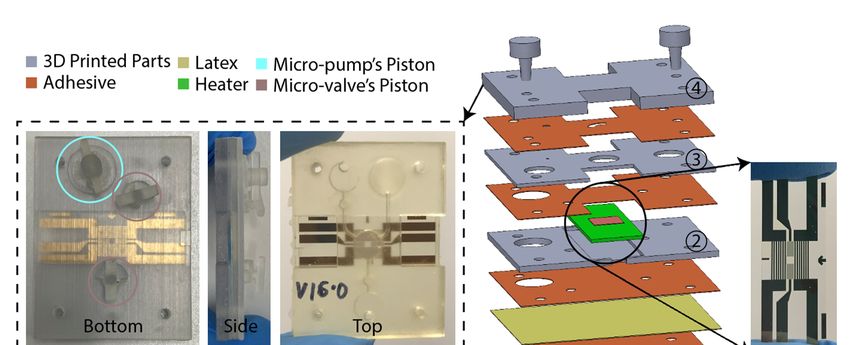
2.5. LAMP-Chip Construction
2.5.The
LAMP-Chip
LAMP-chip was Construction
constructed with multiple 3D-printed parts, PSA, latex mem-
brane, and micro-heater. The overall size of the LAMP-chips is length 4 cm × width 3 cm
The1 cm.
× thickness LAMP-chip was
Figure 4a depicts constructed
the 3D withview)
schematic (exploded multiple 3D-printed
and a photograph of p
membrane, and micro-heater. The overall size of the LAMP-chips is len
the developed LAMP-chip. This chip facilitates two microfluidic features (i.e., micro-pump
and micro-valve) to perform one LAMP reaction per device. Figure 4b depicts the piston’s
3 cm × thickness 1 cm. Figure 4a depicts the 3D schematic (explod
action of the micro-pump and micro-valve, which are based on the working principle
photograph
explained of 2.2
in Sections theand
developed
2.3. The partsLAMP-chip.
of the LAMP-chip This
were chip facilitates
3D printed two mic
using Objet
Eden 260V printer with RGD720 biocompatible material. The
(i.e., micro-pump and micro-valve) to perform one LAMP reaction per PSA cut-out was prepared
using the Roland CAMM-1 GS-24 desktop cutter. The layers of the LAMP-chip were
depicts
aligned thea metallic
using piston’s pin action of the layer
set. A systematic micro-pump and micro-valve,
alignment sequence was followed towhich
working
avoid principle
micro-heater explained
damage. Afterward,in highSections
pressure 2.2
was and 2.3.onThe
imposed parts
the chip of athe LA
using
manual press machine to bond them properly. A proportional–integral–derivative con-
printed using Objet Eden 260V printer with RGD720 biocompatible mate
troller (PID)-based circuitry and firmware was developed to operate the micro-heater. The
out was prepared
micro-heater was calibratedusing
using athe RolandIR CAMM-1
commercial thermometer GS-24 desktop
(manufacturer cutter.
part no.
LAMP-chip
Fluke 64 MAX). The were aligned
control circuitryusing
could be a powered
metallic pin
with set. portable
a 5-volt A systematic layer ali
battery, and
a user interface could be developed to operate with a mobile phone. In this study, the
was followed to avoid micro-heater damage. Afterward, high pressure
experimental setup was controlled with a computer. Figure 4b shows the experimental
the chip
setup, whichusing
has twoamajor
manual
parts, press
(a) PID machine to bond
control circuitry them microcontroller
with Arduino properly. A propo
board, and (b) LAMP-chip
derivative controller on (PID)-based
a 3D-printed holder. circuitry and firmware was develop
micro-heater. The micro-heater was calibrated using a commercial
(manufacturer part no. Fluke 64 MAX). The control circuitry could be p
volt portable battery, and a user interface could be developed to opera
phone. In this study, the experimental setup was controlled with a com
shows the experimental setup, which has two major parts, (a) PID cont
Arduino microcontroller board, and (b) LAMP-chip on a 3D-printed ho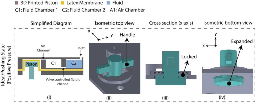
Sensors 2021, 21, 3413
   Sensors 2021, 21, 3413                                                                                                               7 of 14
                                                                                                                                                  7 of 14

                            Figure4.4. LAMP-chip
                            Figure     LAMP-chip(a)      (a)photo
                                                             photoandandexploded
                                                                          exploded     3D3D   schematic.
                                                                                           schematic.    TheThe   primary
                                                                                                               primary      function
                                                                                                                          function       of the
                                                                                                                                     of the  fourfour 3D-
                            printed parts:
                            3D-printed  parts:(1)
                                                (1)supports
                                                     supports the   pistons,(2)(2)supports
                                                               the pistons,         supports thethe   heater,
                                                                                                 heater,       (3) chamber
                                                                                                          (3) chamber         feature,
                                                                                                                        feature,          (4) inlet-outlet
                                                                                                                                 (4) inlet-outlet
                            feature. The
                            feature.  Thelatex
                                          latexmembrane
                                                   membranesupports
                                                                  supportsthethe    functionality
                                                                                functionality         of the
                                                                                                  of the       micro-pump
                                                                                                         micro-pump           andmicro-valve.
                                                                                                                         and the     the micro-valve.
                            (b) Micro-pump’s        push-pull     state and  micro-valve’s        open-close     state.
                            (b) Micro-pump’s push-pull state and micro-valve’s open-close state. Anticlockwise rotation Anticlockwise      rotation
                                                                                                                                             and     and
                            push   action are   required     to create  positive     pressure    (pushing     state). Clockwise
                            push action are required to create positive pressure (pushing state). Clockwise rotation and pulling    rotation   and
                            pulling
                            action   action
                                   are        are to
                                       required     required    to createpressure
                                                       create negative    negative       pressure
                                                                                      (pulling       (pulling
                                                                                                state).         state). (c) Experimental
                                                                                                         (c) Experimental    setup consistssetup
                                                                                                                                               of
                            consists of LAMP-chip
                            LAMP-chip    with the chip withholderthe
                                                                   andchip holder
                                                                        control        andboard.
                                                                                  circuit   control circuit board.

                            3.
                            3. Results
                               Results
                                The performance test of the LAMP-chip was conducted in two phases. First, the
                                The performance test of the LAMP-chip was conducted in two phases. First, the
                            LAMP-chip was tested with the color dye to assess the microfluidic operation, incubation
                            LAMP-chip    wasand
                            chamber sealing, tested with the color
                                                 micro-heater       dye to assess
                                                              performance.         the
                                                                             Second, themicrofluidic
                                                                                         LAMP assayoperation,     incubation
                                                                                                       with purified
                            chamber
                            human    sealing,
                                  genomic  DNAandsamples
                                                   micro-heater   performance.
                                                         and visual  detection wasSecond,  the on-chip
                                                                                   performed    LAMP andassay  with purified
                                                                                                            tube.
                            human genomic DNA samples and visual detection was performed on-chip and tube.
                            3.1. Performance Test
                            3.1. Performance Testthe microfluidic operation. At the initial condition, all valves were
                                 Figure 5 depicts
                            closed, and the micro-pump was in a pushing state. Firstly, the valves were closed, and
                                  Figure 5 depicts the microfluidic operation. At the initial condition, all valves were
                            12.5 µL color dye was loaded into the loading chamber using a pipette (Figure 5a). The
                            closed, and the micro-pump was in a pushing state. Firstly, the valves were closed, and
                            12.5μL color dye was loaded into the loading chamber using a pipette (Figure 5a). The
                            connecting valve was opened, and negative air pressure was initiated by pulling the ai
                            chamber’s piston to transfer the liquid to the amplification chamber. Consequently, the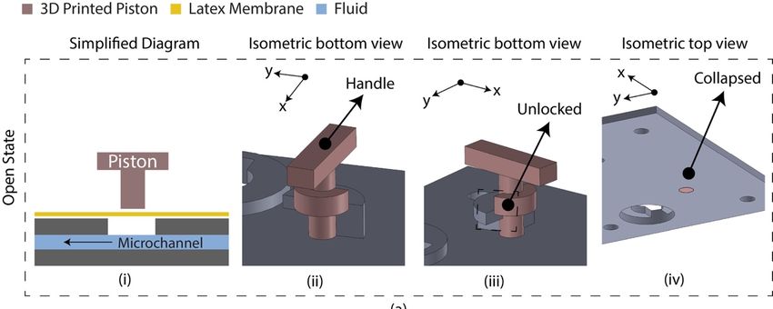
Sensors 2021, 21, 3413                                                                                                     8 of 14

Sensors 2021, 21, 3413                                                                                                         8 of 14
                         connecting valve was opened, and negative air pressure was initiated by pulling the
                         air chamber’s piston to transfer the liquid to the amplification chamber. Consequently,
                         the  fluidboth
                          stage,    moved     to thewere
                                          valves     amplification
                                                           closed tochamber
                                                                         seal the from  the loading
                                                                                     reaction        chamber
                                                                                               chamber.     The(Figure   5b). At was
                                                                                                                   micro-heater
                         this  stage,  both  valves  were    closed  to seal  the  reaction chamber.
                          activated at 65 °C using firmware and heated for 20 min. The firmware analyzedThe   micro-heater  was the
                         activated at 65 ◦ C using firmware and heated for 20 min. The firmware analyzed the
                          temperature sensing electrodes’ resistance, which corresponds to the firmware
                         temperature sensing electrodes’ resistance, which corresponds to the firmware temperature
                          temperature and adjusted the heating electrode’s power in real-time to stabilize the
                         and adjusted the heating electrode’s power in real-time to stabilize the temperature at
                          temperature at 65 °C. In addition to the firmware, the heating chamber’s temperature was
                         65 ◦ C. In addition to the firmware, the heating chamber’s temperature was recorded using
                          recorded
                         the           using theforIRcomparison.
                             IR thermometer            thermometer       for 6comparison.
                                                                    Figure                    Figure 6 shows
                                                                               shows the micro-heater’s           the micro-heater’s
                                                                                                            temperature   profile
                          temperature      profile
                                               2    and  correlation    (R 2 = 0.9783) between the firmware readout and the
                         and correlation (R = 0.9783) between the firmware readout and the reference thermometer
                          reference
                         readout,      thermometer
                                    where   n = 5. Thereadout,     where
                                                        micro-heater    tookn about
                                                                               = 5. The  micro-heater
                                                                                      5 min to reach 65 took   about leakage
                                                                                                         ◦ C. Sample   5 min toinreach
                          65 amplification
                         the  °C. Sample leakage
                                               chamber inwas
                                                           the not
                                                                amplification
                                                                    found in the  chamber    was not
                                                                                    LAMP-chips.     Thefound    in the
                                                                                                         fluid was      LAMP-chips.
                                                                                                                     transferred
                          The   fluid  was   transferred    from   the  amplification    chamber    to the
                         from the amplification chamber to the extraction chamber by opening the connecting  extraction  chamber by
                          opening
                         valve   and the   connecting
                                      initiating          valve
                                                  a positive      and initiating
                                                              pressure               a positive
                                                                         at the air chamber      pressure
                                                                                              to extract  theat  the air sample
                                                                                                              amplified   chamber to
                         (Figure
                          extract5c).
                                    the The   sample sample
                                          amplified    extraction    from the
                                                                 (Figure     5c).extraction
                                                                                   The samplechamber    was performed
                                                                                                  extraction    from the using
                                                                                                                           extraction
                         achamber
                           pipette. was performed using a pipette.

                          Figure5.5. Photograph
                         Figure      Photographof  ofthe
                                                      theLAMP-chip
                                                          LAMP-chipininoperation
                                                                            operationininline
                                                                                            linewith
                                                                                                 withthe
                                                                                                      thecorresponding
                                                                                                          correspondingschematics.
                                                                                                                         schematics. (a)
                          Sample   loading  state, (b) sample   transfer  from   loading  chamber    to amplification chamber,
                         (a) Sample loading state, (b) sample transfer from loading chamber to amplification chamber, followed
                          followed
                         by          by the
                             the sample     sample
                                         heating     heating
                                                 state, and (c)state, andextraction
                                                                 sample    (c) sample   extraction state.
                                                                                     state.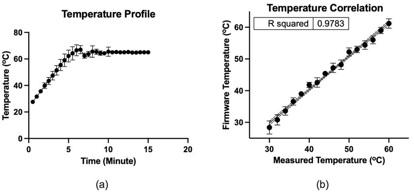
Sensors 2021, 21, 3413 9 of 14
Sensors 2021, 21, 3413 9 of 1
Sensors 2021, 21, 3413 9 of 14
Figure
Figure
Figure 6. 6.
6. (a)(a)
(a) Temperature
Temperature
Temperature profile
profile
profile of theofmicro-heater.
of the the micro-heater.
micro-heater. (b) (b) Correlation
(b)Correlation
Correlation betweenbetween
between the the readout
thefirmware
firmware firmware
readout
and andthethe
the measured
readout and measured
thermometer
measured thermometer by IR by
by IR thermometer,
thermometer IRwhere
thermometer,
thermometer,n =where where
5. The ndots n =dots
5.the
= 5.indicate
The The dotsthe
mean,
indicate indicate
and the the
mean,
error
mean, and
bars
and thethe
representerror
error barsbars
the represent
standard
represent the standard
deviation.
the standard deviation.
deviation.
3.2. LAMP Assay
3.2.
3.2.LAMP
LAMP Assay
Assay
A parallel assay was performed on the LAMP-chip and tube. Table 1 indicates the
AAparallel assay waswas
performed on theonLAMP-chip and tube.andTable
tube.1 Table
indicates the
quantity parallel assay
of each kind performed
with the corresponding the LAMP-chip
controls. The colorimetric master1 mix,
indicates th
quantity of
quantityand each
of the
eachkind with
kind withthe corresponding controls. The colorimetric master mix,
primers, template were the corresponding
mixed in a tube beforecontrols.
loadingThe intocolorimetric
the LAMP-chip. master mi
primers,
primers,and andthethe
template
templatewerewere
mixed in a tube
in a before loadingloading
into theintoLAMP-chip.
Afterwards, the microfluidic operationmixed
was executed tube before
following the sequence the LAMP-chip
detailed in
Afterwards, the microfluidic operation was executed following the sequence detailed in
Afterwards,
Section 3.1, andthethemicrofluidic
tube-based LAMP operation
assay was performed
executed following
in the thermalthe cycler.
sequence In the detailed i
Section 3.1, and the tube-based LAMP assay was performed in the thermal cycler. In the
LAMP-chip,
Section 3.1,the
and color
the started to change
tube-based LAMP about
assay20 was
min performed
into the incubation
in the period, cycler.
thermal and In th
LAMP-chip, the color started to change about 20 min into the incubation period, and the
the differentiation
LAMP-chip, the became
colormoremore
started evident after
to change 25
about min. The color of the positive controls
differentiation became evident after 25 min.20Themin intoofthe
color theincubation period, and th
positive controls
changed to yellowbecame
from themore
original pink color, whereas theThe
negative controls remained
changed to yellow from the original pink color, whereas the negative controls remained contro
differentiation evident after 25 min. color of the positive
unchanged. The color of the positive and negative LAMP amplicons was distinguishable
changed toThe
unchanged. yellow from
color of the the original
positive pink color,
and negative LAMP whereas the negative
amplicons controls remaine
was distinguishable
in ambient lighting conditions for both platforms. Figure 7 shows the color differentiation
unchanged.
in ambient The
lighting color of
conditionsthe
forpositive
both and
platforms.negative
Figure LAMP
7 shows amplicons
the color
of positive and negative control for both platforms. The detection result was found to be
was distinguishab
differentiation
of positive
in same
the ambient and negative
lighting
on both control
conditions
platforms. for both platforms. The
for bothamplification
Non-specific detection
platforms. Figure result
7 shows
in the off- was found
the color
and on-chip to be
testsdifferentiatio
was
the
of same
not on both
positive
observed, and platforms.
negative
in line Non-specific
with ourcontrol
previous amplification
forreport
both platforms.
[19]. in The
the off- and on-chip
detection resulttests
waswas found to b
not observed, in line with our previous report [19].
the same on both platforms. Non-specific amplification in the off- and on-chip tests wa
not observed,
Table in line
1. LAMP assays with
on chip our
and previous
in tube. report [19].
Table 1. LAMP assays on chip and in tube.
Assay Platform Control Type Template Quantity (pcs)
Assay
Table Platform
1. LAMP assays Control Typein tube.
on chip and Template Quantity (pcs)
Positive HLA-B*15:02/HLA B75
LAMP-chip Positive HLA-B*15:02/HLA B75 55
LAMP-chip
Assay Platform Negative
Control Type HLA-B*08:01/HLA
Template B8 2Quantity (pcs)
Negative HLA-B*08:01/HLA B8 2
Positive HLA-B*15:02/HLA
Positive HLA-B*15:02/HLA
HLA-B*15:02/HLA B75 B75 2 5
LAMP-chip Positive B75 2
Tube HLA-B*08:01/HLA B8 2
Tube Negative HLA-B*08:01/HLA
Negative HLA-B*08:01/HLA B8
Nuclease-free water
B8 21 2
Negative
Positive Nuclease-free
HLA-B*15:02/HLA
water B75 1 2
Tube HLA-B*08:01/HLA B8 2
Negative
Nuclease-free water 1
Figure 7. Representative
Representativephotographs
photographsofofthe
theLAMP-chip
LAMP-chipand LAMP-tube
and LAMP-tubeafter
afterthethe
amplification.
amplification.
(a) Positive control
control on
on LAMP-chip,
LAMP-chip,(b)
(b)negative
negativecontrol
controlon
onLAMP-chip,
LAMP-chip,and
and(c)(c)positive
positiveand
andnegative
negative control on
control on LAMP-tube. LAMP-tube.
4.Figure 7. Representative photographs of the LAMP-chip and LAMP-tube after the amplification.
Discussion
(a) Positive control on LAMP-chip, (b) negative control on LAMP-chip, and (c) positive and
negative control on LAMP-tube.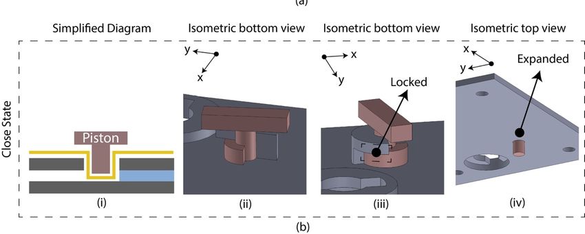
Sensors 2021, 21, 3413                                                                                          10 of 14

                         4. Discussion
                                The micro-valve and micro-pump mechanism required to develop the LAMP-chip
                         can be adopted from different microfluidic operating principles [70–72]. Each of these
                         principles has its unique advantages and limitations. There are no standardized metrics
                         of performance for microvalves and micropumps. They are different in materials, cost,
                         fabrication, portability, biocompatibility, and reusability. The particular properties that
                         make a micro-valve or micro-pump design appealing for one specific application may
                         also exhibit relatively less efficiency in other applications. Hence, these properties should
                         be considered as a whole to determine the design suitability for a particular biomedical
                         application. A range of technical information is available for a microfluidic system which
                         still needs to be incorporated into a tangible device. The commercialization of microfluidic
                         technologies for biomedical applications is still in infancy.
                                In this study, 3D printing technology was exploited to develop the microfluidic device
                         for its unique ability to construct a complex functional structure which would be challeng-
                         ing for another microfluidic platform. Three-dimensional printing is an effective alternative
                         method to fabricate structurally vigorous microfluidic devices [73,74]. The 3D-printed
                         microfluidics’ primary limitation is the printing resolution, which is limited to 200 µm [74],
                         whereas the critical dimension for the developed LAMP-chip is 500 µm, in this study.
                         Rogers et al. [75] demonstrated a 3D-printed valve for a microchannel of 350 µm diameter
                         and limited to opaque material, which is not suitable for optical detection. Wang et al. [76]
                         demonstrated a 3D-printed microfluidic system utilizing a desktop syringe pump with a
                         flow rate of 15 µL/min. Anthony et al. [77] demonstrated a stereo-lithographically printed
                         microfluidic system with optically clear biocompatible plastic, where three-port plug-in
                         style valves were unitized to actuate the microfluid operation. The overall performance
                         of the micro-pump and the micro-valve is similar to other microfluidic systems based on
                         syringe pumps or off-chip electronic valves. The desktop syringe pump-based microfluidic
                         system could be impractical for POCT devices, and the membrane-based microfluidic
                         system would be appropriate. We foresee that this first-generation prototype can be further
                         developed to automate the microfluidic actuation, appealing for POCT devices.
                                In the past decade, research exploring the potentials to translate the LAMP-on-tube
                         technique into LAMP-on-chip due to its unique advantage of single amplification tem-
                         perature and low reagent cost [58]. Several lab-on-a-disk-based LAMP devices have
                         been developed integrating preloaded reagent mixes and detection agents [52,78–80]. Re-
                         searchers have explored paper-based devices for their robustness, cost-effectiveness, and
                         user-friendliness [81,82]. A magnetic bead-based LAMP system was designed to detect
                         methicillin-resistant Staphylococcus aureus (MRSA), integrating nucleic acid extraction and
                         temperature control [83]. Liang et al. developed a LAMP-based thermal digital microflu-
                         idic device called Lamport to detect Trypanosoma brucei, which required SYBR Green I
                         after the amplification for endpoint detection [84]. Multiple LAMP endpoint detection
                         methods have been developed in the past 20 years, such as naked-eye observation of pre-
                         cipitation [85], colorimetric detection [86,87], gel electrophoresis [88], and biosensor-based
                         electrochemical methods [19,89]. A substantial report is available to perform the LAMP
                         reaction on-chip in various microfluidic platforms, but the POC device development for
                         precision medicine such as HLA genotyping is still in infancy.
                                In this study, a LAMP-chip was developed to amplify the HLA-B alleles as the first step
                         of the two-step POC device development process. A diaphragm-based microfluidic system
                         was developed to transport the sample into the reaction chamber and seal the chamber
                         during the high-temperature amplification. In this system, a finger-controlled piston was
                         utilized to execute the microfluidic operation, which can be further developed in the future
                         with an electronic mechanism to automate the operation. A gold patterned heating unit
                         was integrated with the incubation chamber to conduct the LAMP reaction at 65 ◦ C. A
                         two-stage test was performed in this study. In stage 1, the microfluidic system was tested
                         with color dye, indicating successful fluid flow and chamber sealing during incubation.
                         The heating unit showed a correlation of R2 = 0.9783 with a reference thermometer during
Sensors 2021, 21, 3413 11 of 14
the temperature ramp and maintained the temperature at the setpoint with a tolerance of
±1 ◦ C. In stage 2, a colorimetric LAMP master mix was utilized to assess the amplification
outcome in a chip, which is in line with tube assay. This micro-heater unit may also be
combined with an interdigitated electrode (IDE) biosensor [19] in the future.
5. Conclusions
We have developed a LAMP-chip to amplify the HLA-B alleles, which is the first part of
the two-step HLA-B*15:02 detection process. Previously, we reported the LAMP detection
technique for HLA genotyping in a tube-based platform, whereas here, we improved
the technique to perform in the chip for point-of-care application. The chip is featured
with microfluidic operations (i.e., micro-pump, micro-valve, and micro-heater) to perform
LAMP amplification in a portable manner. The microfluidic performance was tested
with color dye, demonstrating microfluidic transportation capabilities, strong temperature
correlation (R2 = 0.9783) with a reference thermometer, and temperature stabilization
(setpoint 65 ◦ C) at 10 min. The micro-valve mechanism can contain the amplicons in
the high-pressure amplification chamber. The color change is visible in ambient lighting
conditions after the 25-min on-chip amplification. The LAMP-on-chip results showed
a complete match with the LAMP-on-tube assay, demonstrating the detection system’s
concordance. This LAMP-chip can be adapted for another nucleic acid amplification-based
biomarker detection when prompt genetic information is required for clinical decisions.
Author Contributions: Conceptualization, S.M.U., J.C., D.H.H., E.S., and P.K.; Data curation, S.M.U.;
Formal analysis, S.M.U., A.S., J.C., D.H.H., E.S., and P.K.; Funding acquisition, P.K.; Investigation,
S.M.U., A.S., J.C., and D.H.H.; Methodology, S.M.U., A.S., J.C., D.H.H., E.S., and P.K.; Project
administration, J.C.; Resources, J.C., E.S., and P.K.; Software, S.M.U.; Supervision, E.S. and P.K.;
Validation, S.M.U., A.S., J.C., D.H.H., E.S., and P.K.; Visualization, S.M.U., A.S., J.C., D.H.H., E.S., and
P.K.; Writing—original draft, S.M.U.; Writing—review & editing, S.M.U., A.S., J.C., D.H.H., E.S., and
P.K. All authors have read and agreed to the published version of the manuscript.
Funding: This research received no external funding.
Institutional Review Board Statement: Not applicable.
Informed Consent Statement: Not applicable.
Data Availability Statement: Not applicable.
Acknowledgments: This work was performed in part at the Melbourne Centre for Nanofabrication
(MCN) in the Victorian Node of the Australian National Fabrication Facility (ANFF). P.K. is supported
by a Medical Research Future Fund Fellowship (MRF113642).
Conflicts of Interest: The authors declare no conflict of interest.
References
1. Bastuji-Garin, S.; Rzany, B.; Stern, R.S.; Shear, N.H.; Naldi, L.; Roujeau, J.C. Clinical classification of cases of toxic epidermal
necrolysis, Stevens-Johnson syndrome, and erythema multiforme. Arch. Dermatol. 1993, 129, 92–96. [CrossRef]
2. Roujeau, J.-C.; Kelly, J.P.; Naldi, L.; Rzany, B.; Stern, R.S.; Anderson, T.; Auquier, A.; Bastuji-Garin, S.; Correia, O.; Locati, F.; et al.
Medication Use and the Risk of Stevens–Johnson Syndrome or Toxic Epidermal Necrolysis. N. Engl. J. Med. 1995, 333, 1600–1608.
[CrossRef]
3. Roujeau, J.-C. Clinical heterogeneity of drug hypersensitivity. Toxicology 2005, 209, 123–129. [CrossRef]
4. Pichler, W.J.; Srinoulprasert, Y.; Yun, J.; Hausmann, O. Multiple Drug Hypersensitivity. Int. Arch. Allergy Immunol. 2017, 172,
129–138. [CrossRef]
5. Shear, H.N.; Spielberg, S.P. Anticonvulsant hypersensitivity syndrome. In vitro assessment of risk. J. Clin. Investig. 1988, 82,
1826–1832. [CrossRef] [PubMed]
6. Fiszenson-Albala, F.; Auzerie, V.; Mahé, E.; Farinotti, R.; Durand-Stocco, C.; Crickx, B.; Descamps, V. A 6-month prospective
survey of cutaneous drug reactions in a hospital setting. Br. J. Dermatol. 2003, 149, 1018–1022. [CrossRef]
7. Chave, T.A.; Mortimer, N.J.; Sladden, M.J.; Hall, A.; Hutchinson, P.E. Toxic epidermal necrolysis: Current evidence, practical
management and future directions. Br. J. Dermatol. 2005, 153, 241–253. [CrossRef]
8. Roujeau, J.C.; Stern, R.S. Severe Adverse Cutaneous Reactions to Drugs. N. Engl. J. Med. 1994, 331, 1272–1285. [CrossRef]
[PubMed]Sensors 2021, 21, 3413 12 of 14
9. Chung, W.H.; Hung, S.I.; Hong, H.S. Medical genetics: A marker for Stevens-Johnson syndrome. Nature 2004, 428, 486. [CrossRef]
[PubMed]
10. Locharernkul, C.; Loplumlert, J.; Limotai, C.; Korkij, W.; Desudchit, T.; Tongkobpetch, S.; Kangwanshiratada, O.; Hirankarn,
N.; Suphapeetiporn, K.; Shotelersuk, V. Carbamazepine and phenytoin induced Stevens-Johnson syndrome is associated with
HLA-B*1502 allele in Thai population. Epilepsia 2008, 49, 2087–2091. [CrossRef] [PubMed]
11. Tassaneeyakul, W.; Prabmeechai, N.; Sukasem, C.; Kongpan, T.; Konyoung, P.; Chumworathayi, P.; Tiamkao, S.; Khunarkornsiri,
U.; Kulkantrakorn, K.; Saksit, N.; et al. Associations between HLA class I and cytochrome P450 2C9 genetic polymorphisms
and phenytoin-related severe cutaneous adverse reactions in a Thai population. Pharm. Genom. 2016, 26, 225–234. [CrossRef]
[PubMed]
12. Tassaneeyakul, W.; Tiamkao, S.; Jantararoungtong, T.; Chen, P.; Lin, S.-Y.; Chen, W.-H.; Konyoung, P.; Khunarkornsiri, U.;
Auvichayapat, N.; Pavakul, K.; et al. Association between HLA-B*1502 and carbamazepine-induced severe cutaneous adverse
drug reactions in a Thai population. Epilepsia 2010, 51, 926–930. [CrossRef] [PubMed]
13. Kaniwa, N.; Saito, Y.; Aihara, M.; Matsunaga, K.; Tohkin, M.; Kurose, K.; Sawada, J.-I.; Furuya, H.; Takahashi, Y.; Muramatsu,
M.; et al. HLA-B locus in Japanese patients with anti-epileptics and allopurinol-related Stevens–Johnson syndrome and toxic
epidermal necrolysis. Pharmacogenomics 2008, 9, 1617–1622. [CrossRef] [PubMed]
14. Alfirevic, A.; Jorgensen, A.L.; Williamson, P.R.; Chadwick, D.W.; Park, B.K.; Pirmohamed, M. HLA-B locus in Caucasian patients
with carbamazepine hypersensitivity. Pharmacogenomics 2006, 7, 813–818. [CrossRef]
15. Chen, Z.; Liew, D.; Kwan, P. Effects of a HLA-B*15:02 screening policy on antiepileptic drug use and severe skin reactions.
Neurology 2014, 83, 2077–2084. [CrossRef] [PubMed]
16. Karlin, E.; Phillips, E. Genotyping for severe drug hypersensitivity. Curr. Allergy Asthma Rep. 2014, 14, 418. [CrossRef] [PubMed]
17. Erlich, H. HLA DNA typing: Past, present, and future. Tissue Antigens 2012, 80, 1–11. [CrossRef]
18. Chen, Z.; Liew, D.; Kwan, P. Real-world cost-effectiveness of pharmacogenetic screening for epilepsy treatment. Neurology 2016,
86, 1086–1094. [CrossRef] [PubMed]
19. Soraya, G.V.; Chan, J.; Nguyen, T.C.; Huynh, D.H.; Abeyrathne, C.D.; Chana, G.; Todaro, M.; Skafidas, E.; Kwan, P. An
interdigitated electrode biosensor platform for rapid HLA-B*15:02 genotyping for prevention of drug hypersensitivity. Biosens.
Bioelectron. 2018, 111, 174–183. [CrossRef] [PubMed]
20. Lei, K.F. Microfluidic systems for diagnostic applications: A review. J. Lab. Autom. 2012, 17, 330–347. [CrossRef]
21. Beebe, D.J.; Mensing, G.A.; Walker, G.M. Physics and Applications of Microfluidics in Biology. Annu. Rev. Biomed. Eng. 2002, 4,
261–286. [CrossRef]
22. Fiorini, G.S.; Chiu, D.T. Disposable microfluidic devices: Fabrication, function, and application. BioTechniques 2005, 38, 429–446.
[CrossRef]
23. Tsai, J.-H.; Lin, L. Active microfluidic mixer and gas bubble filter driven by thermal bubble micropump. Sens. Actuators A Phys.
2002, 97–98, 665–671. [CrossRef]
24. Teymoori, M.M.; Abbaspour-Sani, E. Design and simulation of a novel electrostatic peristaltic micromachined pump for drug
delivery applications. Sens. Actuators A Phys. 2005, 117, 222–229. [CrossRef]
25. Byun, C.K.; Abi-Samra, K.; Cho, Y.-K.; Takayama, S. Pumps for microfluidic cell culture. Electrophoresis 2013, 35, 245–257.
[CrossRef]
26. Huang, P.-H.; Nama, N.; Mao, Z.; Li, P.; Rufo, J.; Chen, Y.; Xie, Y.; Wei, C.-H.; Wang, L.; Huang, T.J. A reliable and programmable
acoustofluidic pump powered by oscillating sharp-edge structures. Lab Chip 2014, 14, 4319–4323. [CrossRef]
27. Terray, A.; Oakey, J.; Marr, D.W. Microfluidic control using colloidal devices. Science 2002, 296, 1841–1844. [CrossRef]
28. Vestad, T.; Marr, D.W.M.; Oakey, J. Flow control for capillary-pumped microfluidic systems. J. Micromech. Microeng. 2004, 14,
1503. [CrossRef]
29. Narayanamurthy, V.; Jeroish, Z.E.; Bhuvaneshwari, K.S.; Bayat, P.; Premkumar, R.; Samsuri, F.; Yusoff, M.M. Advances in
passively driven microfluidics and lab-on-chip devices: A comprehensive literature review and patent analysis. RSC Adv. 2020,
10, 11652–11680. [CrossRef]
30. Ahn, C.; Choi, J.-W. Microfluidics and their applications to lab-on-a-chip. In Springer Handbook of Nanotechnology; Springer:
Berlin/Heidelberg, Germany, 2007; p. 523.
31. Laser, D.J.; Santiago, J.G. A review of micropumps. J. Micromech. Microeng. 2004, 14, R35. [CrossRef]
32. Zhang, C.; Xing, D.; Li, Y. Micropumps, microvalves, and micromixers within PCR microfluidic chips: Advances and trends.
Biotechnol. Adv. 2007, 25, 483–514. [CrossRef] [PubMed]
33. Au, A.K.; Lai, H.; Utela, B.R.; Folch, A. Microvalves and Micropumps for BioMEMS. Micromachines 2011, 2, 179–220. [CrossRef]
34. Kim, J.; Kido, H.; Rangel, R.H.; Madou, M.J. Passive flow switching valves on a centrifugal microfluidic platform. Sens. Actuators
B Chem. 2008, 128, 613–621. [CrossRef]
35. Oh, K.W.; Ahn, C.H. A review of microvalves. J. Micromech. Microeng. 2006, 16, R13. [CrossRef]
36. Amirouche, F.; Zhou, Y.; Johnson, T. Current micropump technologies and their biomedical applications. Microsyst. Technol. 2009,
15, 647–666. [CrossRef]
37. Clime, L.; Daoud, J.; Brassard, D.; Malic, L.; Geissler, M.; Veres, T. Active pumping and control of flows in centrifugal microfluidics.
Microfluid. Nanofluid. 2019, 23, 29. [CrossRef]Sensors 2021, 21, 3413 13 of 14
38. Mohith, S.; Karanth, P.N.; Kulkarni, S. Recent trends in mechanical micropumps and their applications: A review. Mechatronics
2019, 60, 34–55. [CrossRef]
39. Wang, Y.-N.; Fu, L.-M. Micropumps and biomedical applications—A review. Microelectron. Eng. 2018, 195, 121–138. [CrossRef]
40. Zhao, A.; Zhong, Y.-B. Investigation Progress Review of Micropump Based on MEMS. Chin. Med. Equip. J. 2010, 2, 46–49.
41. Iverson, B.D.; Garimella, S.V. Recent advances in microscale pumping technologies: A review and evaluation. Microfluid.
Nanofluid. 2008, 5, 145–174. [CrossRef]
42. Notomi, T.; Okayama, H.; Masubuchai, H.; Yonekawa, T.; Watanabe, K.; Amino, N.; Hase, T. Loop-mediated isothermal
amplification of DNA. Nucleic Acids Res. 2000, 28, E63. [CrossRef] [PubMed]
43. Giuffrida, M.C.; Spoto, G. Integration of isothermal amplification methods in microfluidic devices: Recent advances. Biosens.
Bioelectron. 2017, 90, 174–186. [CrossRef] [PubMed]
44. Craw, P.; Balachandran, W. Isothermal nucleic acid amplification technologies for point-of-care diagnostics: A critical review. Lab
Chip 2012, 12, 2469–2486. [CrossRef] [PubMed]
45. Asiello, P.J.; Baeumner, A.J. Miniaturized isothermal nucleic acid amplification, a review. Lab Chip 2011, 11, 1420–1430. [CrossRef]
[PubMed]
46. Ofner, A.; Moore, D.G.; Rühs, P.A.; Schwendimann, P.; Eggersdorfer, M.; Amstad, E.; Weitz, D.A.; Studart, A.R. High-Throughput
Step Emulsification for the Production of Functional Materials Using a Glass Microfluidic Device. Macromol. Chem. Phys. 2017,
218, 1600472. [CrossRef]
47. Fang, X.; Chen, H.; Yu, S.; Jiang, X.; Kong, J. Predicting Viruses Accurately by a Multiplex Microfluidic Loop-Mediated Isothermal
Amplification Chip. Anal. Chem. 2011, 83, 690–695. [CrossRef] [PubMed]
48. Gansen, A.; Herrick, A.M.; Dimov, I.K.; Lee, L.P.; Chiu, D.T. Digital LAMP in a sample self-digitization (SD) chip. Lab Chip 2012,
12, 2247–2254. [CrossRef] [PubMed]
49. Duarte, C.; Salm, E.; Dorvel, B.; Reddy, B., Jr.; Bashir, R. On-chip parallel detection of foodborne pathogens using loop-mediated
isothermal amplification. Biomed. Microdevices 2013, 15, 821–830. [CrossRef]
50. Torino, S.; Corrado, B.; Iodice, M.; Coppola, G. PDMS-Based Microfluidic Devices for Cell Culture. Inventions 2018, 3, 65.
[CrossRef]
51. Zhou, Q.-J.; Wang, L.; Chen, J.; Wang, R.-N.; Shi, Y.-H.; Li, C.-H.; Zhang, D.-M.; Yan, X.-J.; Zhang, Y.-J. Development and
evaluation of a real-time fluorogenic loop-mediated isothermal amplification assay integrated on a microfluidic disc chip (on-chip
LAMP) for rapid and simultaneous detection of ten pathogenic bacteria in aquatic animals. J. Microbiol. Methods 2014, 104, 26–35.
[CrossRef]
52. Sayad, A.A.; Ibrahim, F.; Uddin, S.M.; Pei, K.X.; Mohktar, M.S.; Madou, M.; Thong, K.L. A microfluidic lab-on-a-disc integrated
loop mediated isothermal amplification for foodborne pathogen detection. Sens. Actuators B Chem. 2016, 227, 600–609. [CrossRef]
53. Ma, X.; Li, R.; Jin, Z.; Fan, Y.; Zhou, X.; Zhang, Y. Injection molding and characterization of PMMA-based microfluidic devices.
Microsyst. Technol. 2019, 26, 1317–1324. [CrossRef]
54. Leclerc, C.A.; Williams, S.; Powe, C.; Zepp, N.; Lipworth, D.; Pensini, E.; Collier, C.M. Rapid design and prototyping of
microfluidic chips via computer numerical control micromilling and anisotropic shrinking of stressed polystyrene sheets.
Microfluid. Nanofluid. 2021, 25, 12. [CrossRef]
55. Selzer, D.; Spiegel, B.; Kind, M. A Generic Polycarbonate Based Microfluidic Tool to Study Crystal Nucleation in Microdroplets. J.
Cryst. Process. Technol. 2018, 8, 1–17. [CrossRef]
56. Liu, S.; Fan, Y.; Gao, K.; Zhang, Y. Fabrication of Cyclo-olefin polymer-based microfluidic devices using CO2 laser ablation. Mater.
Res. Express 2018, 5, 095305. [CrossRef]
57. Cai, J.; Jiang, J.; Gao, F.; Jia, G.; Zhuang, J.; Tang, G.; Fan, Y. Rapid prototyping of cyclic olefin copolymer based microfluidic
system with CO2 laser ablation. Microsyst. Technol. 2017, 23, 5063–5069. [CrossRef]
58. Zhang, H.; Xu, Y.; Fohlerova, Z.; Chang, H.; Iliescu, C.; Neuzil, P. LAMP-on-a-chip: Revising microfluidic platforms for
loop-mediated DNA amplification. TrAC Trends Anal. Chem. 2019, 113, 44–53. [CrossRef]
59. Zhang, Y.; Ozdemir, P. Microfluidic DNA amplification—A review. Anal. Chim. Acta 2009, 638, 115–125. [CrossRef]
60. Lin, X.; Sun, X.; Luo, S.; Liu, B.; Yang, C. Development of DNA-based signal amplification and microfluidic technology for protein
assay: A review. TrAC Trends Anal. Chem. 2016, 80, 132–148. [CrossRef]
61. Bruijns, B.; Van Asten, A.; Tiggelaar, R.; Gardeniers, H. Microfluidic Devices for Forensic DNA Analysis: A Review. Biosensors
2016, 6, 41. [CrossRef]
62. Miralles, V.; Huerre, A.; Malloggi, F.; Jullien, M.-C. A Review of Heating and Temperature Control in Microfluidic Systems:
Techniques and Applications. Diagnostics 2013, 3, 33–67. [CrossRef]
63. Ahrberg, C.D.; Manz, A.; Chung, B.G. Polymerase chain reaction in microfluidic devices. Lab Chip 2016, 16, 3866–3884. [CrossRef]
64. Wu, J.; Kodzius, R.; Cao, W.; Wen, W. Extraction, amplification and detection of DNA in microfluidic chip-based assays. Microchim.
Acta 2013, 181, 1611–1631. [CrossRef]
65. Ahmad, F.; Hashsham, S.A. Miniaturized nucleic acid amplification systems for rapid and point-of-care diagnostics: A review.
Anal. Chim. Acta 2012, 733, 1–15. [CrossRef]
66. Zanoli, L.M.; Spoto, G. Isothermal Amplification Methods for the Detection of Nucleic Acids in Microfluidic Devices. Biosensors
2012, 3, 18–43. [CrossRef]You can also read