Hermes: Data Transmission over Unknown Voice Channels
←
→
Page content transcription
If your browser does not render page correctly, please read the page content below
Hermes: Data Transmission over Unknown Voice Channels

               Aditya Dhananjay, Ashlesh Sharma, Michael Paik, Jay Chen, Trishank Karthik
                       Kuppusamy, Jinyang Li and Lakshminarayanan Subramanian
                                     Courant Institute of Mathematical Sciences, New York University
                               {aditya, ashlesh, mpaik, jchen, tk883, jinyang, lakshmi}@cs.nyu.edu

ABSTRACT                                                                             with extremely poor connectivity in several rural and under-
While the cellular revolution has made voice connectivity                            developed regions [15]. The fundamental roadblock is one
ubiquitous in the developing world, data services are largely                        of economics: due to low purchasing power and low active
absent or are prohibitively expensive. In this paper, we                             user densities (real user-density and not population density)
present Hermes 1 , a point-to-point data connectivity solu-                          coupled with the lack of reliable power and the high capital
tion that works by modulating data onto acoustic signals                             and operational costs for the provider, providing connectiv-
that are sent over a cellular voice call. The main challenge                         ity still remains a loss-making venture. Due to these factors,
is that most voice codecs greatly distort signals that are not                       traditional wired network connectivity solutions have made
voice-like; furthermore, the backhaul can be highly heteroge-                        very little in-roads in rural areas.
neous and of low quality, thereby introducing unpredictable                             In recent years, many developing countries have under-
distortions. Hermes modulates data over the extremely                                gone a cellular revolution with a significant proliferation of
narrow-band (approximately 3kHz bandwidth) acoustic car-                             digital cellular networks in rural areas [7, 3]. In addition
rier, while being severely constrained by the requirement                            to voice calls, these networks provide SMS text messaging
that the resulting sound signals are voice-like, as far as the                       services that can serve as a rudimentary data layer. While
voice codecs are concerned. Hermes uses a robust data                                it is technically easy to provide enhanced data services on
transcoding and modulation scheme to detect and correct                              top of a digital cellular network, economic factors prevent
errors in the face of bit flips, insertions and deletions; it                        the cellular carriers from providing it; the cost of upgrad-
also adapts the modulation parameters to the observed bit                            ing the cellular infrastructure with data-capable hardware
error rate on the actual voice channel. Through real-world                           and software is very high, given the low user densities and
experiments, we show that Hermes achieves approximately                              low purchasing power. As a result, very few carriers pro-
1.2 kbps goodput which when compared to SMS, improves                                vide data connectivity through GSM Circuit Switched Data
throughput by a factor of 5× and reduces the cost-per-byte                           (also known as GSM Fax) and General Packet Radio Service
by over a factor of 50×.                                                             (GPRS); even fewer carriers provide Enhanced Data rates for
                                                                                     GSM Evolution (EDGE) and 3G services.
                                                                                        There are a large number of important services and ap-
Categories and Subject Descriptors                                                   plications that can be enabled by having just a low band-
C.2.1 [Network Architecture and Design]: Network                                     width point-to-point data connectivity solution; these ser-
communications                                                                       vices and applications broadly lie in the domains of micro-
                                                                                     finance, supply-chain management, agriculture and health-
                                                                                     care provisioning. Unfortunately due to the small market
General Terms                                                                        for data services among end-users, there exists little incen-
Design, Experimentation, Measurement, Performance                                    tive for cellular providers to provide enhanced data services
                                                                                     of any kind.
1.     INTRODUCTION                                                                     Under these extreme conditions, we ask the question:
                                                                                     Given the ubiquity of cellular coverage, can we provide any
  The penetration of data connectivity services in the de-
                                                                                     form of data connectivity services over the cellular network?
veloping world has largely remained an urban phenomenon
                                                                                     While SMS is available as a possible data channel, it is ex-
1
  Named after the great messenger of the gods, the guide to                          tremely low-bandwidth, where every SMS message is limited
the underworld and the god of thieves, in Greek mythology.                           to 140 bytes and furthermore, the cost per bit is quite high [1,
                                                                                     4]. In most areas, a single SMS costs between $0.05 to $0.25
                                                                                     which is comparable to per-minute voice call rates [4]. Hence,
                                                                                     if there exists an efficient data connectivity service over the
Permission to make digital or hard copies of all or part of this work for            cellular voice channel, one can enable a new class of mobile
personal or classroom use is granted without fee provided that copies are            data services and also significantly reduce the cost per bit
not made or distributed for profit or commercial advantage and that copies           for data connectivity.
bear this notice and the full citation on the first page. To copy otherwise, to         Unlike the traditional modem setting, providing data con-
republish, to post on servers or to redistribute to lists, requires prior specific
permission and/or a fee.
                                                                                     nectivity over the cellular voice channel is a challenging prob-
MobiCom’10, September 20–24, 2010, Chicago, Illinois, USA.                           lem due to several constraints. First, the acoustic channel is
Copyright 2010 ACM 978-1-4503-0181-7/10/09 ...$10.00.
extremely narrow-band, which inherently limits the achiev-
able data rates. Second, the voice codes used in cellular
networks introduce several unpredictable distortions due to
the use of memoryful codecs; in contrast, commonly used
modulation techniques operate only over memoryless chan-
nels. In addition, the cellular network uses several optimiza-
tions like voice activity detection and automatic gain con-
trol which further distort the underlying channel. Third,
the underlying voice codecs are hard to model or predict
since they are themselves adaptive and continuously change
parameters. Finally, a typical end-to-end voice call path
may traverse a heterogeneous set of network links, thereby
making the underlying channel effectively unknown. This is
especially true in rural areas where the mobile backhaul net- Figure 1: Simplified network topology, showing the rout-
works are point-to-point wireless links built using WiMax, ing path between cell phone A and B.
micro-wave, satellite or other proprietary technologies.
This problem has received relatively little attention. The
few prior efforts [9, 13, 5, 14, 17, 18] in this space have pri- 2. UNPREDICTABLE VOICE CHANNELS
marily concentrated on the case where the underlying voice In this section, we study the challenges involved with
codec is known. One of our explicit design goals is that our transmitting data over a cellular voice channel. We first
modulation algorithm should adapt itself to the unknown present an overview of the cellular infrastructure and then
acoustic channel and not depend on any specific voice codec. discuss the sources of various unpredictable transformations
In this paper, we describe the design, implementation and that the audio signal can undergo along its end-to-end path.
evaluation of Hermes, a data transmission mechanism that
uses the voice channel as an acoustic modem that achieves 2.1 Basic Setting
1.2 kbps with very low bit error rates, while operating over Fig. 1 shows a simplified routing path between two cellu-
unknown voice channels. To motivate the design of Hermes, lar phones. Let us consider only the unidirectional flow from
we show that most of the known modulation techniques com- phone A to phone B. The voice stream from the user (the
pletely fall apart over cellular voice channels. Hermes mod- analog sound waveform) is digitized by A, using a particular
ulates data over the extremely narrowband (approximately voice codec (§ 2.2.2). This digital representation of voice
3kHz bandwidth) acoustic carrier, while being severely con- is transmitted to the base station P , which reconstructs an
strained by the requirement that the resulting sound signals approximation of the analog sound waveforms. Since the
need to be voice-like. Hermes uses a robust transcoding and digital channel between the mobile phone and the base sta-
frame recovery scheme to detect and correct errors in the tion carries real-time voice, there are no retransmissions; this
face of bit flips, insertions and deletions. Hermes can also channel is lossy. The voice codec is designed to tolerate a
adapt the modulation parameters according to the observed certain amount of loss, without a significant reduction in the
bit error rate on the actual voice channel. sound quality as perceived by the ear.
We demonstrate the effectiveness of Hermes through ex- At base station P , these analog waveforms are re-
tensive evaluation of our techniques over different real-world converted to a digital representation, for transmission over
cellular networks. Achieving 1.2 kbps with very-low error link LP X . This digital format is determined by the capa-
rates (bit error rates in the order of 10−5 , with frame error bilities of P and X, as well as the type of communication
rates < 1%) over these unknown voice channel conditions is link LP X . This process (digital → analog → digital conver-
fairly significant, especially when standard modulation tech- sion) is repeated across potentially very hop until it reaches
niques give extremely low throughputs and high bit error the destination base station Q (§ 2.2.4). At Q, the voice is
rates. Hermes can enable a wide-range of network services encoded using the appropriate codec and transmitted to B.
in rural settings which have not been possible before includ- Note that this codec could be different from that used in the
ing rural information services, mobile health-care and new communication between A and P . Finally at B, the analog
forms of mobile banking. We had previously built many of waveform is reconstructed and is played to the user.
these applications purely using SMS as a data layer; when
compared to SMS, Hermes can provide improved throughput 2.2 Challenges
by a factor of 5×, while lowering the corresponding cost-per- Next, we study the properties of the cellular voice channel
byte by over a factor of 50×. (such as the one between A and B in Figure 1). In particular,
The rest of this paper is organized as follows. In § 2, we we examine the various sources of distortion in the audio
examine the cellular voice channel characteristics and ex- signal in order to understand why it is difficult to modulate
plain why the acoustic characteristics (and hence, the data digital information over such channels.
carrying capabilities) of a voice call are so unpredictable. In
§ 3, we describe traditionally used modulation techniques for 2.2.1 Narrowband Channels
transmitting data over an analog carrier, and examine why
Cellular voice channels are designed to carry human
they under-perform over the cellular voice channel. In § 4,
speech, specifically within the frequency range of [300Hz,
we describe the framing, transcoding and modulation tech-
3400Hz]. The audio signal is band-pass filtered at the source
niques in Hermes. We evaluate the performance of Hermes
phone (and potentially, at intermediate hops) where compo-
in § 5, discuss related work in § 6 and present our conclusions
nents outside of this frequency range are removed; this filter-
in § 7.
ing introduces distortions into the transmitted audio stream.Furthermore, a 3kHz channel is very narrowband; in accor- modes of operation and chooses the best mode according to
dance with Shannon’s capacity formula, this severely limits the current wireless link quality and capacity requirements.
the achievable data rate. For instance, if the underlying wireless conditions are bad, it
reduces source coding and increases channel coding to send
2.2.2 Voice Codec Distortions a lower-quality speech signal more robustly over the wire-
Signal distortions introduced by voice codecs pose one of less link. Cellular network providers can also increase the
the biggest challenges to data modulation. Voice codecs number of calls that can be handled by a base station by
digitize the speech at the sender and re-convert to analog forcing phones to switch to a low bitrate codec mode. Since
at the receiver. Modern codecs, as employed by cellular the codec mode can change on the fly and each mode has its
networks including GSM and CDMA, aggressively exploit own characteristics, it is infeasible to accurately predict the
certain speech signal properties to achieve great compression distortions that the codec introduces in a given audio signal.
while still maintaining good speech quality as experienced by
human users. As a result, audio signals that are not voice-
2.2.4 Heterogeneous network links
like are greatly distorted because they violate speech signal As explained in § 2.1, voice travels across multiple hops
properties assumed by the underlying codecs. Below, we from the source to the destination base station. Each inter-
describe how voice codecs leverage human speech properties. mediate link may further transform the encoded voice signal
Memoryful Codecs: These codecs are based on psycho- according to its capabilities and bandwidth constraints, thus
acoustic audio processing techniques that model the speech introducing additional distortions. For example in Figure 1,
input, such that only those characteristics relevant to the intermediate hop Y may transform the received signal into
human speech and auditory system are transmitted. It is a lower bitrate to send over the expensive satellite link LY S .
known that speech waveforms show only small variations These transformations are performed across potentially ev-
over short time scales; in fact, speech can be modeled as a ery hop, and this is another reason why distortions in re-
periodic waveform with a single fundamental frequency, with ceived audio stream are so unpredictable.
occasional bursts of hissing (sibilants) and popping (plosive)
sounds. A large class of voice codecs are based on this 3. TRADITIONAL MODULATION
model of speech, and have their foundations in linear pre- In this section, we examine the fundamental question:
dictive coding (LPC). LPC-based codecs estimate various How do we modulate binary data over an analog acoustic
speech parameters and represent them digitally. Based on carrier? This process is a digital to analog conversion, where
this model of speech described above, LPC approximates the input bit-stream is converted to sounds, which are trans-
the current output sample as a linear function of a few pre- mitted over the voice call.
vious input samples. This memoryful nature leads to the The obvious first question is: Can we simply interface a
output waveforms being different from the input waveforms, traditional modem (or an acoustic coupler) to use the audio
even though they might be perceived to be similar by the channel provided by the cellular voice call? The answer un-
human ear. Audio signals with large variations over short fortunately, is no. Traditional telephone lines operate on a
time scales do not fit the speech model assumed by LPC and memoryless channel, where the concept of signal and noise
therefore are distorted even more. are intuitively clear. The signal is transmitted from one end
Automatic Gain Control (AGC): In order to maintain the to another; along the way, it gets attenuated, and a certain
sound volume in a phone conversation, AGC uses the average amount of noise gets added to it. Unfortunately, cellular net-
output signal level in a feedback loop to control the amount works do not operate under the additive noise model. The
of amplification for subsequent input samples. This implies very concept of noise is unclear in this context, as most of
that the amplitude of the received signal might be quite the distortion is introduced by the voice codec, even before
different from that of the input. it is transmitted from the source cellular phone (§ 2.2.2).
Voice Activity Detection (VAD): Human conversations are As a result, the observed SNR is a direct function of the
typically half-duplex, i.e. only one person tends to speak at currently and previously transmitted data bits. Traditional
a time. VAD detects the presence of speech activity in an modems fail because their modulation techniques operate on
audio stream, so that data transmission can be deactivated channels that exhibit only additive noise properties.
during the silence periods to save bandwidth and battery In this section, we explore two sets of broad techniques
power. VAD distinguishes human voice from background used to perform modulation: keying and multiplexing. As
noise by exploiting the fact that human voice pulses over we shall see, the codec introduces so much noise, that the
time intervals on the order of a second, while background resulting bit error rates are too high to be useful.
noise does not exhibit such pulsing. As a result, if the input
audio signal does not show pulsing in amplitude, it may be 3.1 Keying
filtered out by VAD as background noise. There are three fundamental properties of the acoustic
carrier signal that can be modified (or keyed) in accordance
2.2.3 Adaptive Behavior of Codecs with the input bits: amplitude, frequency and phase. While
Since voice codecs are based on known algorithms, it is more complex modulation schemes can be constructed by
tempting to explicitly model and compensate for the dis- combining two or more of these techniques, we consider them
tortions introduced by these codecs in the data modulation independently.
process. In other words: Given an input audio signal, can
we model and predict the distortions that the codec intro- 3.1.1 Amplitude Shift Keying (ASK)
duces? Unfortunately, such an approach is not practical be- This is a modulation technique, where the amplitude (or
cause many codecs change their operational parameters and strength) of the carrier signal (of frequency fixed at fc ) is var-
modes on the fly. Consider the GSM AMR codec: it has 14 ied in accordance with the data bits being sent. The simplesta0 a1 fc BER a0 a1 fc BER
Input (Hz) (Hz)
1 Output
0.2 0.4 1700 2.7 × 10⁻¹ 0.4 0.6 2000 3.4 × 10⁻¹
0.2 0.6 1700 4.5 × 10⁻² 0.4 0.8 2000 2.2 × 10⁻¹
0.5 0.2 0.8 1700 1.6 × 10⁻² 0.6 0.8 2000 3.8 × 10⁻¹
0.4 0.6 1700 1.9 × 10⁻¹ 0.2 0.4 2300 1.9 × 10⁻¹
Amplitude
0.4 0.8 1700 2.4 × 10⁻¹ 0.2 0.6 2300 6.2 × 10⁻²
0 0.6 0.8 1700 3.0 × 10⁻¹ 0.2 0.8 2300 9.9 × 10⁻²
0.2 0.4 2000 2.6 × 10⁻¹ 0.4 0.6 2300 3.6 × 10⁻¹
0.2 0.6 2000 5.4 × 10⁻² 0.4 0.8 2300 1.4 × 10⁻¹
-0.5
0.2 0.8 2000 4.0 × 10⁻² 0.6 0.8 2300 3.6 × 10⁻¹
-1 Table 1: Performance of ASK (at 1 bit per symbol) for
different a0 and a1 values. Distortions introduced by the
0 50 100 150 200 250 300 350 voice codec lead to very high bit error rates.
Time
Figure 2: Codec induced distortions: ASK at 1 bit Input
per symbol (a0 = 0.2, a1 = 0.8, fc = 1400Hz). Since the 1 Output
input waveform shows large variations in amplitude over
short time scales, the output waveform is significantly
0.5
distorted by the codec.
Amplitude
0
method is binary ASK, where one sinusoid is transmitted per
bit; a 0 and 1 are transmitted as sinusoids of amplitude a0 -0.5
and a1 respectively. While this approach can be generalized
to transmit n bits per sinusoid using 2n unique sinusoids of
different amplitudes, we consider only binary ASK. -1
Fig. 2 shows a simulation of performing ASK over 1 in-
0 100 200 300 400 500 600
put bit per sinusoid, using a software implementation of the
Time
GSM Adaptive Multi Rate (AMR) codec. Intuitively, we
would like a0 and a1 to be far-apart (amplitudes a0 and a1
being quite different), since channel noise will have have a Figure 3: Codec induced distortions: FSK at 1 bit per
smaller probability of modifying the waveforms sufficiently symbol (f0 = 500Hz, f1 = 1500Hz, ac = 0.7). Since the
to cause bit-flipping. However, we observe that the ampli- input waveform shows large variations in frequency over
tude of an output wave can be quite different from that of short time scales, the output waveform is significantly
the corresponding input wave; this is due to the “memory- distorted by the codec.
ful” nature of the codec (see § 2.2.2). In other words, simply
having symbols with far-apart constellation points does not
necessarily lead to better performance, since the codec itself This is a modulation technique where data is transmitted
distorts the waveforms. through discrete frequency changes of a carrier wave (of am-
Suppose we choose parameters such that a0 and a1 are plitude fixed at ac ). The simplest method of performing FSK
nearer to each other. While the amount of noise introduced is binary FSK (BSFK), where we transmit one sine wave per
by the codec is smaller, the waveforms are less resilient to bit. A 0 or 1 is transmitted as a sinusoid of frequency f0 or
channel noise (this figure is not shown). This illustrates the f1 respectively. While this approach can also be generalized
tension between the need to keep symbols close together (to to transmit n bits per sinusoid using 2n unique sinusoids of
please the codec) and the need to keep the symbols far apart different frequencies, we consider only BFSK.
(to maintain resilience against channel noise). Fig. 3 shows a simulation of performing BFSK, using the
To quantitatively study the performance of ASK, we per- GSM AMR codec. Intuitively, we want f0 and f1 to be
form modulation using different values of a0 and a1 . De- far-apart, in order to be able to distinguish the symbols.
modulation is performed using the standard closest neigh- However, this leads to abrupt and large changes in frequency
bor search algorithm: if the received sinusoid has amplitude over short time scales, rendering the audio stream to become
a ≤ a0 +a 1
, the output is 0; else, the output is 1. The results non voice-like; the voice codec therefore significantly distorts
2
are tabulated in Table. 1, and show that the bit error rates to the audio stream. Therefore, we also need to keep the
are very high. symbols close enough (in the frequency domain) to please
The problem is further compounded with larger values of the voice codec.
n, since the distance between certain pairs of symbols can To quantitatively study the performance of FSK, we sim-
be too small to be resilient against channel noise, while the ulate the modulation using different values of f0 and f1 . De-
distance between certain other pairs of symbols might be too modulation is performed using the standard closest neigh-
large, thereby causing the codec itself to distort the waves. bor search algorithm: if the received symbol has frequency
f ≤ f0 +f
2
1
, the output is 0; else, the output is 1. The re-
sults are tabulated in Table. 2, and show that the bit error
3.1.2 Frequency Shift Keying (FSK) rates are approximately an order of magnitude lower than inf0 f1 BER f0 f1 BER
(Hz) (Hz) (Hz) (Hz) Input
1 Output
1600 1700 1.0 × 10⁻² 1700 1900 4.7 × 10⁻²
1600 1800 1.0 × 10⁻² 1700 2000 5.0 × 10⁻³
1600 1900 4.4 × 10⁻³ 1800 1900 4.0 × 10⁻¹ 0.5
1600 2000 1.9 × 10⁻² 1800 2000 1.4 × 10⁻¹
Amplitude
1700 1800 4.7 × 10⁻² 1900 2000 3.0 × 10⁻¹
0
Table 2: Performance of FSK (at 1 bit per symbol) for
different f0 and f1 values. While distortions introduced
-0.5
by the voice codec still lead to high bit error rates, they
are an order of magnitude lower than in ASK.
-1
0 100 200 300 400 500 600 700
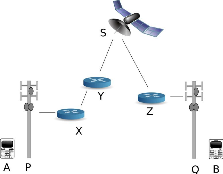
10000
Time
1000
Figure 5: Codec induced distortions: PSK at 1 bit
per symbol (p0 = 0, p1 = π, ac = 0.7). Since the input
waveform shows abrupt transitions at the symbol bound-
Count
aries, the output waveform is significantly distorted by
100
the codec.
10 This is a modulation technique in which digital informa-
tion is transmitted through discrete phase changes of a car-
rier wave (of amplitude and frequency fixed at ac and fc
1 respectively). Similar to ASK and FSK, the number of dis-
1600 1650 1700 1750 1800 1850 1900
crete phases used across the symbol space determines the
Frequency (Hz)
number of unique symbols. Since the phase of the wave-
form changes for every single sinusoid that is transmitted,
Figure 4: Frequency distribution of received symbols this creates a large number of discontinuities (abrupt jumps
for FSK at 1 bit per symbol (f0 = 1700Hz, f1 = 1800Hz). in amplitude) in the time domain signal. Even very small
Observe that the two inverted bell curves significantly changes in phase are sufficient to cause discontinuities in the
overlap, and are not centered correctly. input signal. Since such audio signals are not voice-like, they
get severely distorted by the codec, as illustrated in Fig. 5.
Performing PSK demodulation requires that all symbols
ASK. The intuition behind this difference lies in the funda- are of the same length; in particular, we need to be able to
mental principles of memoryful codecs (§ 2.2.2). Since LPC accurately determine symbol boundaries. Once each symbol
approximates the current sample (samples are in the ampli- has been isolated, it is multiplied by a known sinusoid, and
tude domain) as a linear function of previous samples, it the resulting signal is low-pass filtered to give the original
remembers amplitude components better, leading to greater data. From Fig. 5, we observe that the sinusoids show highly
inter-symbol interference in ASK. Due to the better perfor- varying time-periods, thereby making it virtually impossible
mance of FSK, it is a building block in the modulation layer to perform time synchronization and isolate the individual
of Hermes (§ 4.1). symbols. In effect, this renders PSK impossible to realize
In order to better understand the behavior of the under- over memoryful codecs.
lying voice channel, we examined the frequency distribution
of received sinusoids (f0 = 1700Hz and f1 = 1800Hz). As 3.2 Multiplexing
shown in Fig. 4, the inverted bell curves for the 1700Hz The principle behind Orthogonal Frequency Division Mul-
and 1800Hz sinusoids significantly overlap, which obviously tiplexing is to divide a channel into several non-interfering
makes decoding harder. Furthermore, while the bell curve narrowband sub-channels and encode data at a low rate on
for 1700Hz is centered correctly, the curve for the 1800Hz each sub-channel. The aggregate capacity of the channel is
sinusoid is centered around 1760Hz; this is the reason that therefore the sum of the capacities of all the sub-channels.
the closest neighbor matching demodulator at the receiver Any modulation technique can be used on the sub-channels.
makes so many errors. Finally, we observed that the point at In the context of using OFDM on the 3kHz cellular voice
which the bell curves are centered varies for different codecs; channel, we ask: How many sub-channels can we create, and
thus if different codecs (or codec modes) are used at the two what data rate can each sub-channel achieve?
end points, it is very likely that the demodulation process Assume that the frame size is m bits and we transmit
will yield a high number of bit errors. The important im- one frame in every epoch of time. Further assume that we
plication of this behavior is that our choice of symbols and can divide the 3kHz channel into k orthogonal sub-channels,
demodulator parameters should not be based on any partic- each carrying an independent data stream of b = m bits per
k
ular codec. epoch. Unfortunately, performing OFDM demodulation at
the receiver on such a stream is very hard. The compu-
3.1.3 Phase Shift Keying (PSK) tational resources required to perform fine-grained analogfiltering on the received audio signal (in order to recover the within which the human ear can understand the speech
data on each sub-channel) far exceeds the computational signals.
power of cellular phones, even for small values of k.
The only way around the problem is to ensure that b = 1; • Human speech has a fundamental frequency over long
in other words, each sub-channel carries 1 bit per epoch. durations of time. When arbitrary symbols (sinusoids)
The modulation technique on each sub-channel is in effect are concatenated and sent over the air, the resulting
On-Off Keying, which is a special case of ASK, where a0 and sound stream should also have a fixed fundamental fre-
a1 are 0 and 1 respectively. The receiver determines that the quency.
nth bit of the frame (n ≤ k) is 1 if it can detect the presence • Any pair of symbols must not be too far-apart; oth-
of the nth sub-channel carrier; else, this bit is determined erwise, the codec will introduce distortions. Similarly,
to be 0. This technique is computationally feasible, since any pair of symbols must not be too close together; oth-
the receiver can perform a simple Fast Fourier Transform erwise, the symbols will not be resilient against channel
(FFT) on the received signal over the epoch; the frequency noise. Formally, the distance between the constellation
components of the FFT output give us the bits of the frame. points of any pair of symbols in the trellis diagram
This would not have been possible with b > 1, since it would must be upper and lower bounded.
have necessitated fine-grained and computationally intensive
filtering to recover the individual sub-channels. • Due to AGC (§ 2.2.2), different frequency compo-
Unfortunately, the achievable data rates using multiplex- nents might be amplified (or attenuated) by differ-
ing techniques is very low. For example, we experimentally ent amounts by intermediate hops in the network;
determined that for an epoch size of 100ms, we can trans- we should therefore not rely on the amplitude of the
mit about 20 bits of data (20 sub-channels; 1 bit per epoch output waveforms to be similar to that of the input.
per sub-channel). If we increase (decrease) the epoch length, Furthermore, the generated waveforms should exhibit
then we can use a larger (smaller) number of sub-channels voice-like pulsing, or it may be filtered out by VAD
as well. (§ 2.2.2).
Furthermore due to the memoryful nature of the codecs,
we want to prevent frequency components (sub-channels) of • The acoustic symbols generated by the modulator
one symbol from interfering with those in the next symbol. should not depend on any particular codec or codec
In order to achieve this, we need to leave a guard time of ap- mode. An explicit design principle is that we should
proximately 40ms to let the codec forget components from not train the modulation process offline to optimize for
the previous symbol. Adding a guard interval of 40ms be- any specific codec/mode; it should be generic enough
tween epochs and using the previous example, this works to work over any codec/mode.
out to about 150 bits per second, which is very low. • Algorithms used for coding and modulation should be
This problem is compounded due to the fact that the
simple enough to be run on even the most basic cellular
cellular voice channel has a frequency response behavior,
phones.
such that it carries through only a certain fraction of the
3kHz bandwidth reliably (as shown in Fig. 6 and explained We have designed a simple algorithm (called IncDec) to
in § 4.3.1). This further reduces the practically achievable perform modulation in Hermes. It is explained in Algo-
value of k, thereby reducing the throughput even more. We rithm 1; it can be thought of as being a constant-differential
therefore conclude that the data rates are too low to be use- frequency shift keying technique.
ful.
Algorithm 1 Convert binary data to sound signals to be
4. DESIGN sent over a voice call.
In this section, we explain the design of Hermes. User Given: base frequency fbase , delta frequency δ.
data is first fed into a module that performs framing and f = fbase
for each bit b in the input string do
transcoding. In traditional networks, these two components if b = 0 then
are separated, but in Hermes, they are combined in order to f = f −δ
improve error recovery (§ 4.2). This module breaks the data else
into fixed size chunks and creates a stream of frames from f = f +δ
it. The resulting stream of frames is sent to the modulator end if
(§ 4.1), which converts these bits into sounds that are sent Generate a sinusoid of frequency f
over the actual phone call. On the receiver side, the reverse end for
process is carried out. We now examine each of these stages
in detail. The basic idea of the algorithm is that we have a frequency
f that is initialized to the base frequency fbase . If we read
4.1 Modulation a 0 (or a 1) from the input stream, we decrement (or incre-
For memoryless codecs, the generated audio signal does ment) f by a fixed δ, and transmit a sinusoid of frequency
not need to have any special voice-like characteristics. Mem- f . This modulation has the advantage that all transitions
oryful codecs on the other hand require the input audio sig- are bounded by δ, and hence large jumps can be prevented.
nals to be voice like (§ 2). The design of symbols in Hermes Unfortunately, long strings of 0s or 1s can push the cur-
must therefore satisfy the following requirements: rent frequency f over the permissible limit. Furthermore,
since the frequency of transmitted sinusoids can vary quite
• The generated waveforms should pass the bandpass a lot, it is hard to guarantee a fixed fundamental frequency
filter of [300Hz, 3400Hz], which is the relevant band of the resulting acoustic signal. Also, if there is a long stringof 0s, then the modulator begins to operate in the low fre- current input sample, and a linearly decreasing weightage
quency range, thereby reducing the number of sinusoids that to the preceding samples. Therefore, we expect that when
can be sent per unit time (and hence the throughput). Fi- compared to the previous output symbol, we expect the new
nally, the frequency response of the channel is quite different output symbol to be biased in the direction of the new input
in different frequency ranges (§ 5); the input string to the symbol. This argument is formalized below.
modulator could force it to operate in a frequency range that Let us say that t0 , t1 , t2 , · · · , tk are the samples belonging
the channel does not carry very well. To work around these to the k previous input symbols. Let the corresponding out-
weaknesses, we need to transcode the input stream before put samples be s0 , s1 , s2 , · · · , sk . Without loss of generality,
feeding it to the modulation layer (explained in § 4.2). let us say that the memoryful codec uses a weighted aver-
On the receiver side, the modulator needs to convert the age of the current symbol, along with the previous n sym-
sound signals back into bits. This demodulation algorithm bols. Therefore when input symbol tk was being transmitted
is also quite simple and is explained in Algorithm 2. as output symbol sk , the codec used a weighted average of
tk , tk−1 , tk−2 , · · · , tk−n , in decreasing order of weights. Now
Algorithm 2 Convert received sound signals back into bi- when the codec receives symbol tk+1 , it uses a weighted av-
nary data. erage of tk+1 , tk , tk−1 , tk−2 , · · · , tk−n+1 , again in decreasing
Given: Input sound signal. order of weights; this can be approximated as a weighted
for each sinusoid in the input sound signal do average of tk+1 , sk . This is why the new output symbol is
Let fcurr = frequency of current sinusoid biased in the direction of the new input symbol, relative to
Let fprev = frequency of previous sinusoid the previous symbol output.
if fcurr ≤ fprev then We note that none of the properties of the modulation
Output 0
else layer are dependent on any particular codec or implementa-
Output 1 tion. The explanation given above can be generalized to any
end if memoryful codec or codec mode. Irrespective of the length
end for of history considered or the biasing constants, the general
principles still hold.
At first glance, the intuition behind the demodulation al- 4.2 Framing Transcoding
gorithm might seem vague and unclear. To analyze it, we
show that it can cope with both memoryless codecs that Now that we have examined how the underlying modula-
are used in traditional wireline phone networks as well as tion and demodulation layer works, we explain the higher
memoryful codecs that are used in cellular networks. layer in the stack: framing and transcoding.
This module takes in a stream of bits from the user and
4.1.1 Memoryless Codec breaks them into fixed size chunks. For each chunk, it cal-
culates and appends a 32-bit CRC to it, thereby creating a
In this case, the codec does not assume the sound signal to
frame. It also inserts a fixed preamble between every pair
be voice-like, and therefore does not significantly modify the
of frames. The user data can be easily coded using escape
frequency components of the signal; in other words, the noise
sequences to ensure that the preamble pattern does not ap-
is additive. Hence with a very high probability, the received
pear in it. This stream of frames and preambles is then
waveforms will also have frequencies approximately equal
transcoded.
to those of the transmitted waveforms. Clearly, a transition
Transcoding is defined as a digital to digital conversion of
from f −δ → f or a transition from f → f +δ will be decoded
one encoding to another. In Hermes, we transcode the input
as a 1 by Algorithm 2. Similarly, a transition from f +δ → f
stream into another representation before passing it to the
or a transition from f → f −δ will be decoded as a 0. Unless
modulation layer to be converted into sounds. The goals of
the additive noise introduced by the network is extremely
the transcoding layer are summarized as follows:
high, bit errors do not take place and the demodulation is
correct. • The stream fed by the transcoder to the modulator
should be such that the modulator is able to guarantee
4.1.2 Memoryful Codecs a fixed fundamental frequency.
As explained in § 2.2.2, memoryful codecs produce their
output as a linear function of the previous input samples. • The modulation layer should use a minimum number
There is a greater weightage given to more recent samples of unique frequencies over the air; this minimizes the
as opposed to older samples. distortions. Also, the modulator should keep the value
Let us assume that the last symbol transmitted over the of f within acceptable limits.
air had an input frequency fi , and the corresponding output
• The receiver should be able to recover the original
sinusoid had frequency fo . This sinusoid fo was created by
bit stream with a very high probability, even in the
the codec by taking into consideration the input sinusoid
face of bit insertions, deletions and flips in the post-
fi as well as the previous few sinusoids that preceded fi .
transcoded stream of data that is modulated and sent
Assume that the next input sinusoid has frequency fi + α,
over the air.
where α = ±δ. We ask the question: What can we expect
the output frequency of the next sinusoid to be, relative to Transcoding of the data is performed using a very simple
the frequency fo of the current output symbol? algorithm. It is a 1/2 code, meaning that it takes in one
The answer is that if α = +δ, we expect the output fre- input bit and produces two output bits, as shown below:
quency to be greater than fo . Similarly, if α = −δ, then
we expect the output frequency to be lesser than fo . Any 0 → 01
generic memoryful codec gives a greater weightage to the 1 → 10We make a few observations about the interaction of the is shown in Algorithm 3.
transcoding layer with the modulation layer. Whatever the
original input string, the transcoded stream will have an Algorithm 3 Reverse transcode the data at the demodula-
equal number of 0s and 1s. In particular, any substring con- tor output.
taining an even number (≥ 4) of bits in the post-transcoded Given: Demodulated string s, consisting of post-transcoded
stream will have an equal number of 0s and 1s. Furthermore bits.
it is easy to see that the maximum number of consecutive 0s Given: kmax rep , the maximum permissible number of consec-
or 1s in the transcoded string is 2. As a result, the output utive 0s or 1s in the input.
sound of the modulator has a fundamental frequency fixed for i = 1; i ≤ length(s); i = i + 2 do
b1 = s[i]
at fbase , making it more voice-like. In fact, there are only 3 b2 = s[i + 1]
frequencies that are ever used: fbase − δ, fbase and fbase + δ. if b1 b2 = 01 or b1 b2 = 10 then
At the receiver side, the task of the transcoder is to receive Output 0 or 1, respectively.
2n bits from the demodulator and estimate the n original else
bits that were sent at the transmitter. In the simplest case There is either a bit flip or an insertion/deletion error.
where there are no alignment issues, we can simply use the mi = ErrorM etric(i)
mi+1 = ErrorM etric(i + 1);
following rules: if mi ≤ mi+1 then
The alignment is correct, but there is a bit flip.
01 → 0 Output X
10 → 1 else
We have lost alignment by one bit
However, in the presence of alignment errors (the received i =i+1
bits could have bits inserted and deleted), we can run into Output X on up to kmax rep previously decoded output
trouble. Suppose the original pre-transcoded input stream bits.
was all 0s; the corresponding post-transcoding stream was end if
therefore, 0101 · · · . Now suppose that due to noise, the first end if
sinusoid is lost at the receiver. As a result, the demodulator end for
will output 1010 · · · , which the reverse transcoder will in-
correctly decode as a string of all 1s. Now, there is no way For simplicity, assume that the input to the reverse
of detecting the error. The best we can do is to ensure that transcoder is initially aligned; we will drop this assumption
the pre-transcoded input stream does not have long strings later. Let us now examine why this algorithm works. In
of all 0s or all 1s, by using special escape sequences. Bit- the simplest case where there are no bit flips, insertions or
stuffing techniques like these are very commonly used, and deletions, it is easy to see that the reverse decoder gives us
hence have been omitted from this discussion. For now, as- the correct output.
sume that the maximum of consecutive 0s or 1s permissible Now, let us consider what happens in the case of single bit
is kmax rep . flips. We first need to define the function ErrorM etric(i).
Let us now consider a stream of bits that the demodulator It is a look-ahead function that determines if the alignment
outputs. We still need to determine where the correct bound- boundary is at point i. It reads the input in blocks of 2 bits
aries lie; a wrong decision at this point will lead the rest from i to i + m, where m is the maximum allowable look-
of the stream being incorrectly decoded. Consider the pre ahead. It simply outputs the number of blocks of 2 bits
transcoded input stream 01, which leads to the transcoded it was unable to decode. For example, consider the input:
stream 0110; notice that a 0 → 1 transition in the pre 011010100110. In this case, m0 is equal to 0, since the 2-bit
transcoded input stream leads to a pair of consecutive 1s blocks 01, 10, 10, 10, 01 and 10 are all valid. On the other
in the post transcoded stream. Similarly, a 1 → 0 transi- hand, m1 is equal to 3, since there are 3 decoding errors
tion in the pre-transcoded input stream leads to a pair of in the 2-bit blocks 11, 01, 01, 00 and 11. Since m0 ≤ m1 ,
consecutive 0s in the post-transcoded stream. Therefore, all it is more likely that the alignment boundary lies at 0, as
the reverse transcoder needs to do is identify a 00 or 11 and opposed to the boundary lying at 1.
place the alignment boundary between the two. In the case of single bit flips, the reverse transcoder will
This problem becomes trickier in the face of bit insertions receive either 00 or 11, so it knows that something has gone
and deletions. Even if the reverse transcoder has achieved wrong. It checks to see whether it has lost alignment; if not,
alignment at some point of time, a bit insertion or dele- then the only explanation for the 00 or 11 is bit flipping. In
tion can throw it completely off, leading it to incorrectly this case, the reverse transcoder outputs an X, signifying
decoding the rest of the stream. The problem is further that it does not know how to decode that bit; a higher layer
complicated by the fact that bits can also get flipped; For handles these Xs. If both bits are flipped, then 01 gets
example, a pre-transcoded 0 (post transcoded 01) might get converted 10 and vice versa; these errors are undetectable
flipped to 00 at the demodulator output; this in turn might at this layer; such cases are handled by a higher layer CRC.
force the reverse transcoder into incorrectly believing that In the case of a bit insertion or deletion, the decoder
it has lost alignment. The intuition behind differentiating might not determine that an error has taken place imme-
an insertion/deletion error from a flip error is that former diately; in fact, the reverse transcoder could potentially
actually leads to a loss of alignment, whereas the latter does continue outputting up to kmax rep bits. Take for exam-
not. A bit flip leads to only one block of 2 bits being de- ple the input stream 001111110 · · · , which is transcoded
coded incorrectly, whereas an insertion/deletion error leads to 010110101010101001 · · · ; assume that kmax rep = 6 pre-
to subsequent blocks (of 2 bits each) also being decoded transcoded bits. Suppose this bit stream is demodulated
incorrectly. The algorithm to detect (post-transcoded) bit at the receiver with a 0 bit insertion after the first 4 bits:
flips, insertions and deletions is based on this intuition, and 0101010101010101001 · · · . The reverse transcoder will read0101010101010101 to output 00000000. At this point, it en- 10
Input
counters a 00 and determines by looking ahead that it has Output
in fact, lost alignment. At this point, it loses confidence in
8
the previous kmax rep bits that it output, and replaces them
all with X. In reality, we need not X-out all kmax rep out-
put bits; it can be proved that we only need to X-out only 6
Amplitude
the previous p output bits, where p is the number of output
bits ago, where a 0 → 1 or 1 → 0 transition took place in
4
the output of the reverse transcoder. If there were no such
transitions in the last kmax rep output bits, then we need to
X-out all of the previous kmax rep output bits. 2
We now examine the rationale behind why Hermes merges
the functionality of the framer and the transcoder. Con-
0
sider the final output of the reverse transcoder, a string 0 500 1000 1500 2000 2500 3000
s ∈ {0, 1, X}∗ . It breaks the stream into individual frames Frequency (Hz)
using the predefined preamble as a delimiter. Unfortunately,
if the delimiter itself has an X, then the frames on either Figure 6: FFT of the input and output audio signals.
side of it will be lost. Peaks are expected at 300, 360, 420, 480, · · · Hz. There are
Consider a frame (data + CRC) in {0, 1, X}∗ . The next a few false peaks, and many missing peaks. This experi-
step is to attempt to recover the frame by filling up the Xs ment probes the frequency response of the channel.
with the correct bits. An X could be 0 or 1 (bit flipping),
00, 01, 10 or 11 (bit deletion) or the N U LL character (bit in-
sertion). It brute-force searches through all possible values as we find reasonable initial values, Hermes can fine tune
that all the Xs could take; with a very high probability, only the parameter set on the fly.
one of them will satisfy the checksum; this is the frame that
is passed up to the higher layer. We could also attempt to re- 4.3.2 Fine Tuning
cover frames that are on either side of a corrupted delimiter; In order to understand the rationale behind our fine tun-
currently, this is beyond the scope of our solution. ing algorithm, we need to examine how the error rate varies
as a function of fbase and δ. We conduct an experiment over
4.3 Parameter Choice an actual phone call, where the data has been modulated us-
We ask the question: What are the best values of fbase and ing different values of fbase and δ. Fig. 7 plots the resulting
δ for the best performance? Hermes uses a very simple search bit error rates, as a function of fbase and δ. Assume that the
and estimation algorithm to find initial values of fbase and optimal parameter values are fbase ˆ and δ̂. If we keep fbase
δ. During the progress of the actual call, these parameters ˆ and vary δ, we observe that as δ moves away
fixed at fbase
can be fine-tuned on the fly. from δ̂, the error rate increases. Similarly, as fbase moves
away from fbaseˆ , the error rate increases. It illustrates the
4.3.1 Initial Parameter Set fact that once we have chosen an initial parameter set, we
The first step is to estimate the frequency response of the can vary fbase and δ and observe how the error rate changes.
underlying voice channel. To do this, we choose a small num- We can then use any standard hill climbing algorithm to find
ber (say, 50) of unique frequencies that are uniformly spaced the optimal parameter set.
between the range [300Hz,3400Hz]. These frequencies are The advantage with this approach is that as the sender
multiplexed and sent over the air with an epoch of 200ms. varies its parameter set, the receiver can continue to run its
Fig. 6 shows the input and output FFTs superimposed over demodulation algorithm unchanged. The demodulator does
each other. not depend on any constants or parameters; its output only
From Fig. 6, we observe a very interesting pattern in the depends on the relative difference between the frequency of
frequency response of a particular voice channel that we the current sinusoid and that of the previous sinusoid.
tested. In particular, in the band of approximately [500Hz,
1500Hz], the data is almost completely lost. On the other 4.4 Overcoming VAD and AGC
hand, the range of [2000Hz, 2500Hz] is carried through To overcome VAD, we need our audio stream to pulsing
quite reliably. Above 2500Hz, we can observe a few false in amplitude over long time scales. In Hermes, we employ a
peaks as well. The power of this observation is that with a simple trick to fool VAD into believing that there is human
simple test of 200ms, we can probe the frequency response voice on the channel. Each second of the audio stream is
of the channel to understand what frequency components broken up into 2 pieces of 0.5s each. The first piece is left
are carried through cleanly. untouched; the amplitude in second piece is scaled down to
Let us say that fmax is the frequency that had the high- 0.7 of the original. To overcome AGC, we need to make sure
est peak in the FFT output; this is (albeit, approximately), that the amplitude in the audio stream is not very low. The
the frequency that the channel carries through the best. In amplification factors mentioned above (1.0 and 0.7) are high
Hermes, we set the initial value of fbase to fmax . To find a enough that we do not expect AGC to kick in. However we
good initial value of δ, we use the following intuition. If δ is note that in our algorithm, we do not modulate data based
too large, then the memoryful codec will severely distort the on the amplitude of the carrier. Therefore, even if AGC
waves; if we use very small values of δ, then channel noise kicks in and clips some samples, the correctness of Hermes
might cause decoding errors. We find that setting δ to be is not compromised. As far as VAD and AGC are concerned,
approximately within 10 − 25% of fbase works well. As long the audio stream transmitted by Hermes is normal speech.fbase (Hz) δ(Hz) BER
85 AT&T → AT&T 2200 480 1 × 10⁻⁵
80
T-Mobile → T-Mobile 2400 640 1 × 10⁻⁵
−0.5
AT&T → T-Mobile 2170 470 1 × 10⁻⁵
75 T-Mobile → AT&T 2130 640 1 × 10⁻⁵
−1
70
Table 3: Performance impact of heterogeneous cellular
−1.5
65 service providers. In all cases, Hermes finds operational
parameters that provide high throughput and extremely
60
δ
−2
low error rates over actual voice calls.
55
−2.5
50
45
−3 We repeat these experiments across sender - receiver pairs
on different cellular service providers. For each pair, we
40
−3.5 present the experimentally observed optimal fbase and δ val-
35
ues, along with the bit error rate. From Table. 3, we observe
340 350 360 370 380 390 400 410 420
fbase that Hermes is able to find parameter configurations that
yield very low error rates, while providing high throughput.
Furthermore in all cases, we observe a very similar error
Figure 7: Logarithm (to base 10) of the error rate as a landscape to that illustrated in Fig. 7; due to its similarity,
function of fbase (340-420Hz) and δ (40-80Hz). The land- it has been omitted.
scape shows that any standard hill climbing algorithm
could be applied to find local minima. 5.2.2 Error Patterns
In order to further understand the bit error patterns, we
consider the experiment over an actual voice call, repeated
5. EVALUATION over different ranges of fbase and δ. We consider those con-
figurations (< fbase , δ > pairs) that result in bit error rates
5.1 Methodology and Implementation of 10−3 to 10−4 bits per second, and analyze when exactly
The algorithms used for transcoding, modulation, demod- those bit errors took place in time. We observed that bit
ulation and decoding are all quite simple, since we would errors occur uniformly and independently of each other; in
like them to run directly on cellular phones, which are not other words, they do not show bursty behavior. We con-
necessarily high-end. However, since we are still prototyping firmed that this behavior held true across heterogeneous
and testing the protocols, these algorithms are currently im- service providers as well. Furthermore, we observed that
plemented on regular desktop computers that interface with although bit insertions and deletions do take place, a signif-
and use the cellular phones as the underlying physical com- icant majority of errors are simple bit flips.
munication channel. We are in the process of implementing
the algorithms on the Android [6] platform. 5.3 Effect of the Transcoding and Framing
Layers
5.2 Raw Channel Throughput and Error Next, we examine how much of the pre-transcoded data
Rate can be recovered, in the face of bit insertions, deletions and
We first would like to understand what the raw bit er- flips into the post-transcoded stream. Since it is difficult to
ror rates are for the post-transcoded stream, which is trans- control the error rates from the underlying voice channel, we
mitted over the actual voice call. In this experiment, we conduct a simulation as follows. Break the input stream into
operate both end points of the voice call over the cellular chunks of 26 bytes, which when concatenated with the 32-bit
service provider AT&T (data from experiments conducted CRC, give us packets of 30 bytes. There is a 1-byte preamble
across heterogeneous cellular service providers is presented between packets, consisting of all 0s. This stream of packets
in § 5.2.1). Fig. 7 plots these error rates, as a function of (with the accompanying preambles) constitute the stream s.
fbase (340-420Hz) and δ (40-80Hz). We repeat this exper- There are totally 103 packets in this experiment. Perform
iment for fbase in [2200Hz, 2400Hz] and δ in [300-800Hz], the 1:2 transcoding on s, to get a bit stream t. Artificially
and observe a very similar error landscape with a large num- introduce errors (insertions, deletions and flips) into t to
ber of data points showing error rates in the order of 10−4 get t̂. Pass t̂ through the reverse transcoder to get the bit-
to 10−5 . Due to its similarity to Fig. 7, it has been omitted. stream ŝ. The next step is to use the delimiter (preamble) to
Since a 1 : 2 transcoding is performed before modulation recover to frames from this stream; note that these frames
and transmission over the voice call, the approximate good- may contain Xs. Finally, use the frame recovery method to
put (data rate of the original pre-transcoded stream) is fbase
2
fill up the Xs and pass the frame up to the higher layer if the
bits per second. This shows that we can achieve a goodput CRC check is successful. Note that we attempt to recover
of up to 1200 bits per second quite reliably over the voice only those packets that have between 1 and 4 Xs in them;
call. Furthermore, the end-to-end frame success rate is al- if the number of Xs is large, the computational complexity
most 100% (see § 5.3 for a deeper analysis on frame success to attempt recovery is prohibitively high.
rates, as a function of the underlying bit error model and To study the effect of bit flips, insertions and deletions,
rate). we consider them separately. In § 5.2.2. we have observed
that the underlying bit errors are independent of each other
5.2.1 Heterogeneous Cellular Service Providers (in other words, they are not bursty); we therefore modelInsertion Deletion Flips fbase (Hz) δ(Hz) BER
No Yes No Yes No Yes AMR → AMR 2340 420 1.6 × 10⁻⁴
1 × 10⁻² 0.8 4.1 1.2 3.2 1.2 34.3 AMR → EFR 2280 645 1.8 × 10⁻³
7 × 10⁻³ 3.5 10.4 3.0 10.5 3.0 58.9 EFR → AMR 2280 630 1.9 × 10⁻³
4 × 10⁻³ 14.4 33.6 13.6 32.3 13.6 84.9 EFR → EFR 2265 585 2.6 × 10⁻³
1 × 10⁻³ 60.7 81.7 60.0 78.5 60.0 96.1
7 × 10⁻⁴ 70.1 86.3 70.4 85.6 70.4 97.9 Table 5: Performance impact of heterogeneous codecs
4 × 10⁻⁴ 81.3 91.6 81.4 91.6 81.4 99.1 on operational parameters and performance of Hermes.
1 × 10⁻⁴ 95.1 98.6 94.8 97.9 94.8 99.8 Irrespective of the codecs used, Hermes is able to achieve
low error rates, with high throughput.
Table 4: Frame success rate (expressed as a percentage)
for different underlying bit error rates. The transcoding
layer is able to guess the X values to successfully recon-
struct many damaged frames. We compare against the most 4, and therefore all errors will be detected. However,
case where no recovery of Xs is attempted (labeled “No”). by attempting to recover frames with up to 4 Xs in them,
we significantly improve the frame success rate. In this case,
the Hamming distance between any two valid code-words is
at most 8. While we expect the CRC to catch a very high
fraction of these errors, it is not guaranteed. We can imple-
the bit errors as a uniform error distribution. We repeat ment any block coding mechanism (such as Reed-Solomon)
each experiment for a set of different error rates (fraction of at a higher layer to detect and correct such errors.
bits that are flipped, inserted or deleted), and the results are
presented in Table. 4, from which we observe that even under 5.4 Effect of Heterogeneous Codecs
high underlying bit error rates, Hermes is able to correctly We observed that AT&T and T-Mobile force the phones
recover a large fraction of damaged frames. The table also to operate over the AMR codec. We suspect the reason is
shows what the frame error rate would be, if there were no that since we are in a highly dense urban environment, the
attempts to reconstruct damaged frames (labeled as “No” in carriers can force the AMR codec to operate on lower bitrate
the table). (and hence, lower quality) modes, in order to optimize base
The performance of the frame recovery layer in Hermes station capacity. Our attempts to test Hermes over the EFR
is better under bit flip errors, as opposed to insertion and codec failed, since AT&T and T-Mobile have disabled the
deletion errors. This is due to the fact that each bit flip phone codes to change the codec. We therefore conduct
creates exactly one X, while each insertion or deletion er- a simulation using a software implementation of the EFR
ror can create up to a maximum of kmax rep Xs in the codec and the default mode of the AMR codec. For different
reverse transcoded stream (in our implementation, we set pairs of codecs used at the senders and receivers, we present
kmax rep = 8). Since we aim to recover frames that have the optimal performance numbers in Table. 5. The first
≤ 4 Xs, we do not even attempt to recover a large number observation is that irrespective of the codecs used, Hermes
of frames under the insertion and deletion error models. If is able to achieve low error rates, with high throughput. The
Hermes is run on devices with higher processing capabilities, next observation is that depending on the codecs used, the
we could attempt to recover frames with a larger number of optimal operational parameters are different.
Xs. We have also observed that the frame recovery layer Another important observation we make is that the opti-
in Hermes is able to successfully recover almost all packets mal parameter set for one set of codecs might significantly
with ≤ 4 Xs in them. under-perform for another set of codecs. For example, for
As observed in § 5.2.2, a majority of errors are simple bit EFR → EFR, the optimal parameter set is (fbase = 2265Hz,
flips. From Table. 4, we can see that the transcoding and δ = 585Hz). If we use the same parameters for AMR
framing layer in Hermes significantly improves the frame → AMR, we get a high bit error rate, of approximately
success rates under the bit flip model, even when the under- 5.6 × 10⁻² . The implication is that we cannot train or deter-
lying bit error rate is in the order of 10−3 . For example, for mine the symbols beforehand, since we do not know what
error rates of 1 × 10⁻² , 7 × 10⁻³ , 4 × 10⁻³ and 1 × 10⁻³ , codecs (or codec modes) are going to be used.
Hermes achieve an improvement in frame success rate by a It is important to observe that the real world performance
factor of 28×, 19×, 6× and 1.5× respectively. numbers across heterogeneous cellular service providers (Ta-
ble. 3) are different from the simulation results for heteroge-
5.3.1 CRC Collisions neous codecs presented in Table. 5; in fact, we are able to
We ask the question: What is the probability of a recon- achieve significantly lower bit error rates in the real world.
structed frame passing the CRC check, while being different For example, the AT&T → T-Mobile call was probably in
from the original frame? We know that CRC32 has a Ham- fact an AMR → AMR call. This disparity can be explained
ming distance of 4; this means that if we take a correct code- due to the fact that we simulate over just one mode of AMR,
word (frame payload + corresponding CRC) and choose any whereas in the real world, the AMR codec might keep ad-
n ≤ 4 bits to replace with random values, we will always justing its parameters on the fly for optimal performance.
be able to detect the error. For n > 4 flips, this probability
reduces with increasing n. During recovery in Hermes, each 5.5 Economic Analysis
X can be expanded as 0, 1, 00, 01, 10, 11 or NULL. The The average time taken to send an SMS message is about
simplest work-around is to upper bound the number of Xs 5 seconds; since the payload of an SMS is 140 bytes, this
in a frame to 2, should we attempt to recover it; the Ham- works out to a data rate of 224 bits per second. When com-
ming distance between any two valid codewords will be at pared to SMS, Hermes therefore provides a 5× improvementYou can also read