Hydropower Technology and Environment - Vattenfall AB 2021 - EPD Portal
←
→
Page content transcription
If your browser does not render page correctly, please read the page content below
Hydropower
Technology and Environment
Appendix to EPD® of Electricity from Vattenfall’s Nordic Hydropower
                            S-P 00088

                   Vattenfall AB 2021
                 Confidentiality class: None (C1)
Table of Contents
1.                  Introduction                                                                  3
2.                  Electricity generation in a hydropower plant                                  4
2.1.                The power plant                                                               4
2.2.                Energy conversion                                                             5
3.                  Dams and reservoirs                                                           5
3.1.                General                                                                       5
3.2.                Embankment (earth- and rock-fill) dams                                        6
3.3.                Concrete dams                                                                 7
4.                  The power plant                                                               7
4.1.                General                                                                       8
4.2.                Turbines                                                                      8
4.3.                Generator and transformer                                                     10
4.4.                Waterways: Penstocks, tail races and surge chambers                           10
5.                  Environmental impact                                                          11
5.1.                General                                                                       11
5.2.                Emissions of oils and lubricants to soil and water                            11
5.3.                Impacts caused by Hydropower Regulation                                       11
5.4.                Landscape and Land-use                                                        12

 Vattenfall AB Vattenfall AB         Hydropower                                                            2 (14)
 2021                                Technology and Environment
 Confidentiality class: None (C1)    Appendix to EPD® of electricity from Vattenfall’s Noridc hydropower
1. Introduction
This is an appendix to Vattenfall’s certified Environmental Product Declaration EPD® for electricity from
hydropower in the Nordic region.

Vattenfall BU Hydro Nordic operate, develop and are responsible for 84 whole- or part owned hydro power plants
in Sweden and Finland. The hydropower generation that BU Hydro Nordic disposes from majority owned plants
during an average year is 31 TWh which corresponds to about half of the total hydro power production in Sweden.
Several reservoirs enable the generation to follow the load curve, and electricity can be delivered without backup
sources.

The hydropower technology was developed at the end of the 19th century, and the first time the kinetic energy of
water was used for the generation of electricity was in 1882. Large-scale hydropower development was started in
Sweden during the 1910’s and reached its peak between 1950 and 1970. The access to hydropower electricity
was of importance for the industrialisation process in Sweden. Electricity was a prerequisite for developing
industries like forestry and mining, and for the extension of the railway network.

The hydrological cycle, the continuous circulation of water from ocean to atmosphere to land and back to the
ocean through evaporation, condensation, precipitation and runoff, is a prerequisite for hydropower. This
circulation is run by the, in the foreseeable future, non-exhaustible solar radiation and gravity, making hydropower
a renewable source of energy.

Hydropower, like all types of energy conversion, affects the environment. The regulation of a watercourse and the
construction of dams, reservoirs and power plants affect and change the landscape and the natural environment.
Where there used to be rapids and streams, water reservoirs are created that are more similar to lakes in their
appearance. Land reclamation destroys or changes forest areas, arable land and natural habitats, which in turn
affect land use for forestry, agriculture, reindeer husbandry, fishing and tourism. With these transformations of the
landscape the preconditions for flora and fauna changes.

The purpose of this appendix is to describe the different technical solutions for the generation of hydropower
electricity, and how the environment is affected by the technology.

Vattenfall AB 2021                      Hydropower                                                               3 (14)
Confidentiality class: None (C1)        Technology and Environment
                                        Appendix to EPD® of electricity from Vattenfall’s Nordic Hydropower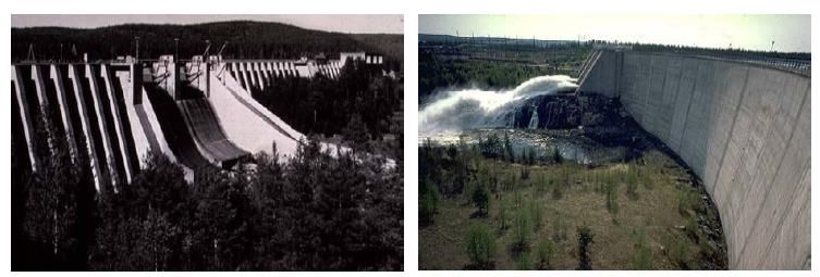
2. Electricity generation in a hydropower plant
2.1. The power plant
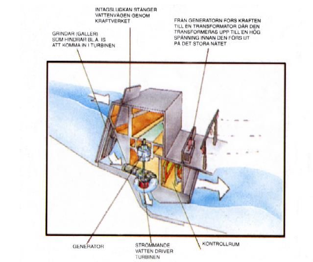
The figure below shows a schematic drawing of a hydropower plant. The various parts are described in detail
below.
Intake gate closes the
waterway through the
power plant The power is transferred from the
generator to the transformer where it
Trash racks that keep e.g.
is stepped up to a higher voltage
debris and ice from entering
before it can enter the grid
the turbines
The generator converts the Flowing water Control room
kinetic energy from the running runs the turbine
turbine to electrical energy
Figure 1 Schematic drawing of a hydropower plant
Vattenfall AB 2021 Hydropower 4 (14)
Confidentiality class: None (C1) Technology and Environment
Appendix to EPD® of electricity from Vattenfall’s Nordic Hydropower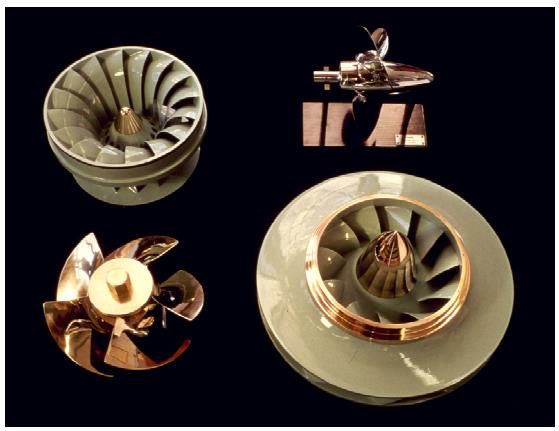
2.2. Energy conversion
Energy can never be spent; it only changes state. In hydropower, the difference in potential energy between two
points in a river is used. The potential energy that is lost when water loses altitude is mainly converted to kinetic
energy. The kinetic energy of flowing water is converted to mechanical energy in the turbine, whose runners are
turned by the water. The mechanical energy is transferred via an axle to the generator where it is converted to
electrical energy. The electricity is then stepped up in a transformer to the voltage of the grid and distributed to
customers.

The recoverable energy from any given stretch of river is directly proportional to the discharge and the head
(height of the fall), that is the amount of water per time unit and the vertical distance between the water surfaces
upstream and downstream in the utilised stretch of river.

There are two principal approaches to achieving enough head for a hydropower plant:

Moderate heads (5-35 m) can be created by impounding the water in a river by constructing a dam wall – an
obstacle consisting of earth, rock or reinforced concrete. The water level above the dam wall is raised compared
to the natural level. The powerhouse (above-ground) is placed in the dam structure. The head can be increased
by dredging and excavations downstream of the dam wall.

With high heads (in Sweden up to around 300 m), e.g. between two lakes, it is possible to construct long rock
tunnels (sometimes combined with channels and/or pipes), possibly several km long, in which the water is
conducted. The powerhouse is placed underground in a rock cavern. The outlet of the upper lake is closed by a
dam, which might also raise the water level so that the lake can be used as a reservoir.

A head of 1 m and a discharge of 1 m 3/s yield an available power of 9,8 kW which, when the efficiency ratio of the
plant (normally 80-90%) has been factored in, yields the electrical capacity.

The amount of electrical energy (often expressed in the unit kWh), which can be generated in a hydropower plant
with a certain capacity, depends on the availability, i.e. the share of the time that water can be passed through the
turbines.

3. Dams and Reservoirs
3.1. General
Since it is difficult to store electricity in a cost-efficient way, the total generation must correspond to the market
demand at all times. By storing water in a reservoir, the generation can be increased quickly as demand
increases or another generation unit, e.g. a nuclear plant, shuts down. Since precipitation varies from year to year
and between seasons, access to large reservoirs which can store parts of the annual or seasonal runoff and
partly eliminate the difference between dry and wet years are valuable. Such reservoirs are called seasonal or
annual reservoirs, and Vattenfall’s largest reservoirs are Storuman on the Ume River, Suorva on the Lule River
and Lake Vänern (Sweden’s largest lake). .

The demand for electricity also shows a diurnal variation (e.g. a peak during the morning hours) as well as a
response to the outdoor temperature. For this reason, there are also many smaller reservoirs on the rivers that
are used for the daily and weekly regulation of electricity generation. This phenomenon is also known as
“hydropeaking”.

Dams have to be able to withstand the pressure from the impounded water. Dams are categorised into gravity
dams and arch dams depending on their static mode of operation, and into embankment dams and concrete
dams depending on their construction material. Gravity dams carry the water pressure with their own weight, and
can be built from all of the construction materials mentioned. Arch dams carry the water pressure through their
arching action, and are built almost exclusively of reinforced concrete. Dams are designed and constructed in
different ways depending on the natural conditions in each individual case. For safety reasons, all dams are
equipped with spillways to enable the release of excess water during very high discharges in the river and to
ensure minimum flow if the turbines would stop. This excess water is water that cannot be stored in the reservoir
in spite of the turbines working at full capacity. The water is then routed past the dam through the spillway gates,
or over the top of the dam on overflow dams.

Vattenfall AB 2021                      Hydropower                                                                 5 (14)
Confidentiality class: None (C1)        Technology and Environment
                                        Appendix to EPD® of electricity from Vattenfall’s Nordic Hydropower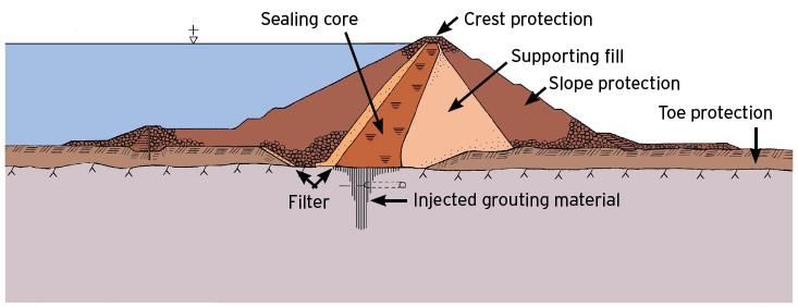
3.2. Embankment (earth- and rock-fill) dams
These dams constitute the most common dam type in Sweden. It is generally best suited to situations with low to
medium-height dams with a long crest. They are gravity dams and are constructed with sufficient weight to be
able to withstand water pressure and erosion from the impounded water. The dam wall mainly consists of
compacted earth (moraine, sand, gravel) or blasted rock. As a consequence of the chosen technology, the cross
section becomes relatively large. Base widths of over 100 metres are not unusual, creating a need for large
amounts of fill material.
Embankment dams consist of different zones (see figure below):
A sealing water-tight core limits the flow of water through the dam wall.
Filter zones keep material from being removed from the core.
Support zones give the dam stability.
Grouting, the rock is injected with concrete in order to prevent seepage of water through natural cracks and
fissures under the dam wall.
Erosion protection is found superficially on the slope and protects against wave action, ice, precipitation and
flooding.

Figure 2 Schematic sketch: cross section of an earth/rock-fill dam

Vattenfall AB 2021                                Hydropower                                                            6 (14)
Confidentiality class: None (C1)                  Technology and Environment
                                                  Appendix to EPD® of electricity from Vattenfall’s Nordic Hydropower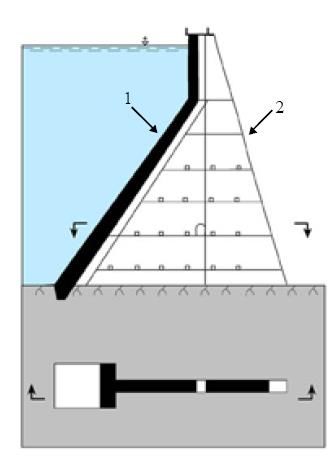
3.3. Concrete dams
Concrete dams are primarily used for medium-high to high dams. They are considerably slimmer than
embankment dams. In Sweden, concrete dams are represented by both gravity dams and arch dams.

Gravity dams are similar in appearance to embankment dams, and are characterised by the way the dam’s own
weight keeps it from overturning. The dam’s weight stabilises the pressure from the water and transfers it to the
underlying ground through friction. In order to achieve enough weight and stability, the cross section is either
triangular or trapezoidal, and the crest straight. Buttress dams have a non-permeable sloping face slab (1) which
is supported by a number of concrete pillars/buttresses (2). A buttress dam is stabilised by its own weight aided
by the water pressure on the face slab. The weight of the water is transferred via the face slab to the buttresses
and down into the bedrock. Arch dams are rare in Sweden. Simply put, they consist of a wall of reinforced
concrete with high structural strength. The wall is curved with the convex side turned upstream towards the
reservoir. The figure shows an arch dam from above. Arch dams are comparatively thin and light in comparison to
gravity dams, and can withstand extensive movement in the bedrock, provided these movements are evenly
distributed along the dam’s extension. The arching action transfers most of the horizontal force of the water to the
bedrock at the lateral contact. The ideal location for an arch dam is in very narrow sections (canyons), and where
the rock walls are capable of carrying the resulting load.

Figure 3 Illustration of a buttress dam to the left and an arch dam to the right

Figure 4 Downstream views of, on the left, a buttress dam and, on the right, an arch dam.

4. The Power Plant

Vattenfall AB 2021                                  Hydropower                                                            7 (14)
Confidentiality class: None (C1)                    Technology and Environment
                                                    Appendix to EPD® of electricity from Vattenfall’s Nordic Hydropower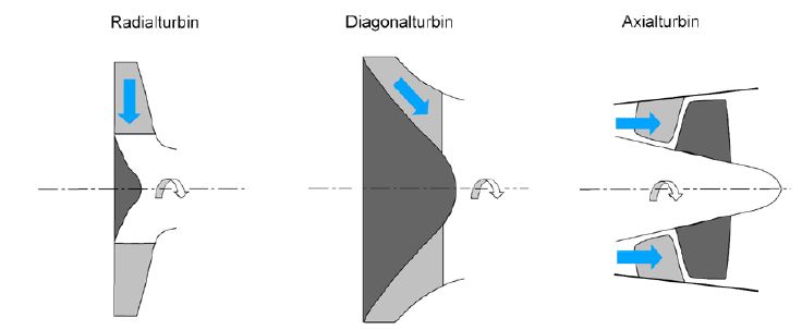
4.1. General
The potential energy of the water is converted to electric energy in a hydropower plant, with a water turbine
connected to a generator. Depending on the head and discharge, different types and sizes of turbines and
generators are utilised.

4.2. Turbines
A turbine consists of a runner with blades, mounted on an axle. In so-called impulse turbines, the runner rotates
freely in air at atmospheric pressure, while in reaction turbines it is submerged in water and built into a turbine
casing. In large reaction turbines, one normally tries to harness the kinetic energy remaining in the water after it
has passed the turbine. This is accomplished with a funnel-shaped draft tube, where the flow of the water slows
down and the pressure increases with the distance from the turbine, creating a negative pressure under the
turbine. This creates a suction effect.

According to the direction the water is led into the turbines, they are divided into axial, radial, and diagonal
turbines. In an axial turbine, the water is led in parallel with the axle. If the water passes through the turbine at an
angle, it is a diagonal turbine, and if the water enters at a right angle to the axle, it is a radial turbine.
            Radial turbine                     Diagonal turbine                    Axial turbine

Figure 5 The principles for radial-, axial and diagonal turbines. The blue arrows show the direction of the incoming water.

Table 1 The most common turbine types
 Turbine                             Type                                             Capacity range                 Head
 Kaplan                              Reaction turbine, axial                          0-200 MW                       10-80 metres
 Francis                             Reaction turbine,                                0-700 MW                       15-700 metres
                                     radial/diagonal
 Pelton                              Impulse turbine, radial                          0-500 MW                       >100 metres

Vattenfall AB 2021                                 Hydropower                                                                        8 (14)
Confidentiality class: None (C1)                   Technology and Environment
                                                   Appendix to EPD® of electricity from Vattenfall’s Nordic Hydropower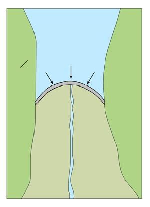
Figure 6 Runners for Kaplan turbine (upper left), Propeller turbine (upper right), Francis turbine (lower left), Francis turbine for high
heads (lower right).

Kaplan turbines are axial reaction turbines and are used for low heads (10-80 metres) and large discharges. The
runner‘s few blades are adjustable, and it is similar to a regular boat propeller where the flowing water makes the
propeller rotate. The turbine casing is spiral-shaped and has adjustable wicket gates. The water is led through an
access tube to the turbine casing, via the wicket gates and the runner to the draft tube. The sub-surface turbine is
completely filled with water. The water exits the turbine through the funnel-shaped draft tube. The flow through the
turbine, and thus the capacity, is regulated with the adjustable runner blades and wicket gates. Each position of
the gates corresponds to an optimum angle of the blades. The adjustments are controlled hydraulically.

For certain applications there are Kaplan turbines with fixed blades, called propeller turbines, and in small power
plants Kaplan turbines with fixed wicket gates, so called semi-Kaplan turbines.
Another variety of Kaplan turbines is the so-called bulb (or tubular) turbines. In a bulb turbine, the turbine axle is
placed horizontally with the generator sitting on the same axle, enclosed in the “bulb”. Bulb turbines are used for
low heads.

A Francis turbine is a radial or diagonal reaction unit, and is used in applications with medium heads (15-700
metres) and large discharges. The design resembles a mill wheel on its side. The turbine casing is spiral-shaped
and has adjustable wicket gates. Incoming water is led through the access tube to the spiral casing, through the
adjustable wicket gates and the fixed runner vanes to the draft tube. This type also has the turbine casing entirely
submerged under water. The exiting water is led out axially through the curved draft tube. The water flow through
the turbines is controlled by the hydraulically operated wicket gates.

Pelton turbines are used for high heads and low discharges. They are radial impulse turbines, which also
resemble a mill wheel where the runner wheel is equipped with double buckets in place of vanes. In contrast to
the other two main types of turbine, the runner is situated above the level of the down-stream water surface. This
means that the runner rotates in air at atmospheric pressure. The runner is made to rotate by radially incoming
water which, via a nozzle and a jet deflector, hits the buckets tangentially. Exiting water falls through the outlet to
the down-stream water surface. The flow through the turbine is hydraulically regulated by changing the setting of
a needle in the nozzle. Since the water, via the valves, does not hit all the runner vanes at the same time, lower
discharges can be utilised at high efficiencies in a Pelton unit, which is not true for Kaplan and Francis units.

Vattenfall AB 2021                                  Hydropower                                                                              9 (14)
Confidentiality class: None (C1)                    Technology and Environment
                                                    Appendix to EPD® of electricity from Vattenfall’s Nordic Hydropower
4.3. Generator and transformer
The turbine and the generator work jointly by rotating on the same axle. The generator converts the mechanical
energy of the turbine into electrical energy. The generator voltage is normally 10-20 kV. In order to be able to
transfer the electrical energy from the power plant to the consumers with minimum losses from the transmission
lines, high voltage is needed (130-400 kV) so the voltage of the generated electricity is stepped up to that of the
high-voltage grid in a transformer.
4.4. Waterways: Penstocks, tail races and surge chambers
At the upstream end, the water is led via an intake structure to the turbine in vertical or steeply inclined shafts
called penstocks. After having passed through the turbine and draft tube, the water is led out through a tailrace
tunnel and back to the natural river down-stream of the power plant. Penstocks and tailraces are normally blasted
out of the rock alongside the natural flow of the river.
When the flow of water into a power plant changes, e.g. when the plant is shut down for maintenance, or during
sudden stoppages, the water in penstock and tailrace starts to oscillate. This phenomenon is called surging. To
reduce and even out the forces created by the surge, some hydropower plants are equipped with a special tunnel
called a surge chamber. Also, open waterways above and below the plant can experience some stage variations
due to surging.
Figure 7 Schematic view of the waterways in an underground hydropower plant
Vattenfall AB 2021 Hydropower 10 (14)
Confidentiality class: None (C1) Technology and Environment
Appendix to EPD® of electricity from Vattenfall’s Nordic Hydropower5. Environmental Impact
5.1. General
While hydropower is a stable source of renewable energy it has also wrought about an unmistakable change in
the natural landscape and environment. Hydropower development has taken place over a long period, with
varying levels of ambition and requirements from an environmental point of view. Environmental issues are very
complex and of an inter-disciplinary nature.
Early on, consideration for other business and human activities dominated. Today, the preservation of biodiversity
is considered of paramount importance. This aspect was initially not considered at all by society, and this has led
to shortcomings in the background data available for the evaluation of such impacts today. Studies of Swedish
rivers have shown that species normally do not disappear immediately when hydropower is developed in the
catchment. However, an ecological impact is evidenced by changes in the species composition (some species
become more common, others less so), as different species place different demands on their environment, which
changes as a result of the development. With the exception of the banks of the multi-year reservoirs, hydropower
development rarely causes the complete elimination of species and/or habitats.
The direct emissions from hydropower plants are relatively small and mainly consists of oils and lubricants.
5.2. Emissions of oils and lubricants to soil and water
Hydropower plants contain oils and lubricants of various types. Moving parts need greasing; certain components
are controlled by oil-filled hydraulic systems; and transformers are cooled with oil. Regular maintenance
instructions and the installation of supervisory equipment, oil separators, retaining structures etc., are used to
minimise the emission to the biosphere.
Francis and Kaplan turbines have adjustable guide vanes in their turbine casings, which are controlled
hydraulically. Kaplan turbines also have adjustable runner vanes with a hydraulic oil system in the boss of the
turbine. These oil-filled control systems are located in or near the flowing water, and can leak out into the water
body in the event of a breakdown. Kaplan turbines contain between 1,5 and 30 m3 of oils, and Francis turbines
1,5-10 m3. Small amounts might also leak through, e.g. a bad gasket, before any warning system can sound the
alarm. Pelton turbines, on the other hand, have no hydraulic systems in contact with the waterways.
Transformers are cooled with oil, but are placed in pits that catch any oil that may leak. Rainwater gathering in the
transformer pits is taken care of in case it is contaminated by oils.
Intakes and spillway gates can in some cases be operated by hydraulic oil systems containing between 0,2-15 m3
of oil (depending on the size of the system and number of gates).
A large emission of oil could potentially cause damage to animals and plants in the river environment. The
probability of a major oil leak is, however, very small, since strict precautionary measures are in place. During
major overhauls, the oils are exchanged for environmentally more benign ones. Another recurrent measure is the
modernisation of the turbine control systems. By changing to a high-pressure system, the total volume of oil can
be reduced by 90%.
5.3. Impacts caused by Hydropower Regulation
The construction of dams and power plants have altered the landscape. Where there were previously rapids and
streams the inundation (or flooding) of land have created reservoirs, changing the rivers natural habitats and
ecological functions. The inundation of land changes the surrounding areas, destroys and changes forests,
wildlife habitats, agricultural land, and scenic lands which in turn directly affects land use such as forestry,
reindeer herding, fishing, agriculture and tourism.
Alteration of flow
One of the great advantages of hydropower is flexibility and adjustability in both short- and long term, providing
stable energy production over an entire year. An effective planning of the storage and use of water for power
generation combined with a large storage capacity in reservoirs, a large part of the annual inflow is stored and
redirected to periods when electricity is most needed. This also means that the natural flow of the river changes.
Many ecological features that are characteristic for non-regulated rivers are linked to natural changes in flow. The
natural high flows and flooding of land areas during spring flood are absent since the water will be stored and
allocated to other times of the year. The natural flux of material and nutrients between the river and its
surrounding terrestrial areas is thus negatively affected.
Vattenfall AB 2021 Hydropower 11 (14)
Confidentiality class: None (C1) Technology and Environment
Appendix to EPD® of electricity from Vattenfall’s Nordic HydropowerThe large natural variations in flows and water level between spring and winter in non-regulated rivers is replaced
by a more evenly distributed flow over the year. In some places the flow can be zero past the power plants during
periods with low energy demand. This is done to conserve water to periods with high energy demand.
Since power generation uses the vertical drop to utilize the kinetic energy stored in water, the waters flow is in
some places diverted into tunnels. The water is directed through the power plants turbines, leaving stretches of
the natural riverbed dry. This is probably one of the most apparent visual and negative consequences of
hydropower regulation.
All of this has caused a significant change of appearance and ecological function in the regulated rivers.
A changed environment
This directly affects the species associated with the natural river. Migrating species such as salmon and trout are
blocked from reaching their former spawning sites. Furthermore, the alteration of the rivers’ hydromorphology has
often meant that these spawning sites no longer exist or are significantly reduced. As a result many of the species
that existed before the regulation and were characteristic for the unregulated river are disadvantaged and reduced
in number whereas other species such as perch and pike, that are more adapted to the changed conditions,
become more abundant.
What is done to reduce the impact?
In a few places where natural spawning grounds still remain, Vattenfall have built fish ladders. For instance, this
have been done in Stornorrfors in the Ume river. Generally though, the salmon, trout, grayling and whitefish
populations are maintained through stocking. To compensate for this, Vattenfall owns and operates five
compensation breeding farms and release 1,8 million fishes each year. In the Lule river Vattenfall release 550 000
salmon and 100 000 trout every year as a compensatory measure. The genetic variation of the stock of Lule river
salmon and trout is maintained through an extensive breeding program. In a similar manner this is done in several
other rivers and BU Hydro Nordic is one of the largest operators of salmon and trout hatcheries in Sweden.
The European eel stock is an example of a species in decline and in 2007 EU decided on a stock and recovery
plan. In 2011 a joint program between the major power companies in Sweden, called “Krafttag ål”, was started to
address this issue. The goal is to halve the average hydropower mortality in rivers where the participants have
operations and to increase the stocking of juvenile eel. This is done through a combination of different measures,
for instance trap and transport of eel past the hydropower stations to be released into sea.
Vattenfall are also increasing R&D efforts to investigate the possibility of strengthening natural habitats in
regulated rivers and/or to create new habitats, develop more efficient technical solutions for fish passage etc.
A work in progress
As described above, the regulation of water and change of natural environment is the most tangible impact of
hydropower. At the same time, it is the most difficult issue to manage because it often requires relatively
extensive measures. To maintain the unregulated river's natural environment combined with the regulated rivers
power generation is simply not possible. A fossil-free and renewable energy production as well as a viable natural
environment are both important national goals for Sweden. The governance of good ecological and chemical
status is an important part of the EU Water Framework Directive.
A trade-off must be made between how different types of environmental adaptation increases the ecological
status in the regulated rivers versus how it affects the ability to supply a stable source of renewable energy.
This has proven to be a huge challenge. The power companies in Sweden, in cooperation with governmental
agencies and scientists, are investigating the possibilities of environmental adaptation in a balance between
energy and the national and European environmental goals. The effectiveness of different mitigation measures
such as fish ladders and ecologically adapted flows are at the focus of discussion. According to the National Plan
for modern environmental conditions for hydro power, all Swedish hydro power stations and the watercourses
they operate in will have their environmental conditions and permits tested systematically in the Land and
Environment Courts. This is done to ensure that environmental improvements are made in those places where
they are most cost efficient and best balanced in relation to maintaining the energy production. This work is in
progress and will be an integrated part of Vattenfall’s future operations. The first two of Vattenfall’s smaller hydro
power stations have already started on the reassessment process now.
5.4. Landscape and Land use
Historical development
It is obvious that values have changed regarding landscape and aesthetics since the establishment of the first
impoundments. In modern planning, there is an environmental awareness that was lacking in the early days of
Vattenfall AB 2021 Hydropower 12 (14)
Confidentiality class: None (C1) Technology and Environment
Appendix to EPD® of electricity from Vattenfall’s Nordic Hydropowerindustrialisation. The first large hydropower plants, Trollhättan (Göta river), Älvkarleby (Dal river) and Porjus (Lule
river), which were constructed during the 1905-1915 period, were designed as national monuments in the
landscape. They represented a gateway to the “New Sweden”, a new era with development and prosperity, and
significant resources were spent on the design of the plants and their surroundings. Well-known architects were
hired. The plants were intended to function as examples of progress and community spirit. Therefore, they show
many aspects of environmental planning, not in the sense of the green environment, but rather the surroundings
of the plant.
However, differences are obvious between e.g. Porjus and Trollhättan. The large amounts of blasted rock were
mainly placed in the dam in Porjus, but the surplus was deposited without environmental concerns in spoil dumps
down-stream from the switchyard. The difference between the considerable care exercised in the town
(Trollhättan) and its surrounding populated areas is contrasted with what was done in the wilderness (Porjus),
where one had free access to the natural resource, a typical attitude for that time.
During the 1940’s, approximately twenty hydropower plants were built around the country, and large river
catchments were regulated at the same time. This is the period during which the debate over environment,
conservation and resettlement really started in earnest. The positive attitude towards hydropower development
was no longer a foregone conclusion. The government’s opinion regarding the need for electricity was decisive –
quick action was of the essence! Environmental issues played a minor role and were not dealt with in the
permitting procedures in the Water Court. The only issues dealt with there were encroachment, impoundment,
fishing and floating of timber. The excess amount of blasted rock was the most important environmental impact to
be dealt with. Roads were constructed at a rate not previously seen, and the entire landscape was changed.
One of the main features of landscape architecture during the forties and fifties was the pre-planning of not just
the plant and dam, but also of the spoil dumps, etc. The disposal of these was no longer treated as an
afterthought. The idea was to blend into the landscape, to the extent that this was possible. During the later part
of the fifties, this changed. The goal was no longer a “natural landscape”, but instead the terraces were shaped
like buildings in the landscape. The hard edges, straight lines and open surfaces typical of rational construction
work were emphasised.
This resulted in a management problem since the bare slopes were prone to heavy erosion. Where brush tended
to take over, significant clearing was necessary in order to maintain the desired openness. Messaure (in the Lule
river), finished in 1963, is, in many ways, typical of this opinion that the power plant should be an independent
body in the landscape and not camouflaged. The enormous dam, the reservoir and the large tailrace canal
become dominant features in the landscape. In fact, an entirely new landscape is created.
A changed landscape
The development causes changes to the landscape of both a permanent and a temporary nature. The area
around a seasonal reservoir is normally severely affected. The choice of location can affect both the type of
damage, as well as its magnitude. During the construction period, there are often disturbances to the hydrology,
primarily through increased turbidity and sediment transport. The level of impact depends on natural conditions
and on the mitigation measures.
The water level in lakes is often much higher after regulation than even the previous high-water mark. When
areas that were previously vegetated are covered with water, erosion may follow. The seasonal storage also
reduces discharge in the river during parts of the year,
The reduced risk of floods is often seen as a positive impact of the development. The regulation reduces both the
frequency and magnitude of floods. However, problems can occur at high discharges in some cases, depending
on the operational strategy for the plants. During periods with very high runoff, floods may still occur, something
that has been obvious during the extreme weather conditions of recent years. Apart from this, there is also the
very remote possibility of a dam break, which would cause floods in regulated rivers.
Quarries, spoil dumps and infrastructure
The construction of embankment dams demands a large amount of material, which can be sourced partly from
the blasting of tunnels and waterways. However, materials with special characteristics, to safeguard the function
of the dam, either in the form of soil or rock for embankment dams, or cement and ballast for concrete dams, have
to be sourced from special quarries. These quarries can damage or destroy individual environmental features,
and can affect water quality if they are located close to a watercourse or in an area that is later inundated by the
project.
Tunnels and shafts are blasted into the rock, and the blasted material is very often used in the construction of the
dam or to blend the facilities into the landscape. However, sometimes there is too much blasted material, which
then has to be dumped near the power plant. It is difficult to establish vegetation cover in certain types of spoil
material, and trees, whose roots can damage the dam, cannot be planted on it. This has a negative impact on the
landscape.
Vattenfall AB 2021 Hydropower 13 (14)
Confidentiality class: None (C1) Technology and Environment
Appendix to EPD® of electricity from Vattenfall’s Nordic HydropowerQuarries and spoil dumps affect the landscape and the ecology, and can create open wounds in the landscape.
The construction of access roads in previously undisturbed areas causes fragmentation, which can affect certain
species of animals, primarily large mammals that shy away from artificial structures in the landscape. The dry
riverbeds can also cause migration obstacles for wildlife and the semi-domesticated reindeer herds that try to
pass.
Reindeer herding
Hydropower development in the northern Swedish rivers has affected reindeer herding for several Sami
(indigenous people in the north,) villages. The main issues are loss of grazing areas, loss of migration routes and
impacts on infrastructure. Access to food in the winter is decisive for the size of the reindeer herds.
The construction has caused damage and encroachment, which has led to extra work for the Sami. Where the
original river was used as a guiding obstacle during migration, they now have to put up fences. The
impoundments have also made the use of old fords difficult or impossible.
During the development phase, roads were constructed into the mountains, and abattoirs for the reindeer industry
were often built in conjunction with these. These roads have considerably improved access into the high mountain
areas.
Tourism and recreation
Boat travel becomes more difficult or even impossible in parts of the regulated river, while the reservoirs
sometimes improve communications during the summer. The regulation has caused insecure ice during the
winter, and it is often difficult to judge where the ice is competent or not. The construction and/or improvement of
roads in conjunction with the construction and operation of hydropower plants in the northern Swedish rivers has
improved communications for remotely located dwellings. This has had positive impacts both for people living in
these remote rural areas, as well as for recreation and tourism.
Vattenfall AB 2021 Hydropower 14 (14)
Confidentiality class: None (C1) Technology and Environment
Appendix to EPD® of electricity from Vattenfall’s Nordic HydropowerYou can also read