Illumio Core Version 20.1.0 - PCE Installation and Upgrade Guide - Illumio Technical ...
←
→
Page content transcription
If your browser does not render page correctly, please read the page content below
Illumio Core®
Version 20.1.0

   PCE Installation and Upgrade Guide

August 2021
20000-200-20.1.0
Legal Notices

      Copyright © 2021 Illumio 920 De Guigne Drive, Sunnyvale, CA 94085. All rights
      reserved.
      The content in this documentation is provided for informational purposes only and is
      provided "as is," without warranty of any kind, expressed or implied of Illumio. The
      content in this documentation is subject to change without notice.
      Product Versions
      PCE Version: 20.1.0 (Standard Release)
      VEN Version: 20.1.0 (Standard Release)
      C-VEN Version: 20.1.0
      NEN Version: 2.0.0
      CLI Tool Version: 1.3.0
      Kubelink Version: 1.2.0
      FlowLink Version: 1.1.2
      Standard versus LTS Releases
      20.1.0-PCE and 20.1.0-VEN are standard releases. Illumio will designate a version of
      20.x.x as a Long Term Support (LTS) release. Do not upgrade the PCE or VEN to
      20.1.0 if your environment requires an LTS release.
      For information on Illumio software support for Standard and LTS releases, see Ver-
      sions and Releases on the Illumio Support portal.
      Resources
      Legal information, see https://www.illumio.com/legal-information
      Trademarks statements, see https://www.illumio.com/trademarks
      Patent statements, see https://www.illumio.com/patents
      License statements, see https://www.illumio.com/eula
      Open source software utilized by Illumio Core and their licenses, see Open Source
      Licensing Disclosures
      Contact Information
      To contact Illumio, go to https://www.illumio.com/contact-us
      To contact the Illumio legal team, email us at legal@illumio.com
      To contact the Illumio documentation team, email us at doc-feedback@illumio.com

PCE Installation and Upgrade Guide 20.1.0                                                    2
Contents
Chapter 1 Overview of PCE Installation 6
About This Installation Guide 6
How to Use This Guide 6
Before Reading This Guide 6
Notational Conventions in This Guide 7
PCE Installation Overview 7
Nodes and Clusters 7
Single-node Clusters 8
Software Distribution: PCE and UI Packages 9
Chapter 2 Prepare for PCE Installation 10
PCE Installation Planning 10
Planning Checklist 10
PCE Capacity Planning 11
PCE Storage Device Partitions 17
Port Ranges for Cluster Communication 22
Requirements for PCE Installation 22
Load Balancer Requirements 22
PCE IP Address 23
DNS Requirements 23
SMTP Requirements 23
TLS Requirements 24
(Optional) Configure SAML IdP for User Login 27
OS Setup and Package Dependencies 27
About Your Organization Name and ID 36
Run ilo-pipgen and ilo-vpngen 37
Configure iptables on PCE Hosts with ilo-pipgen 37
Deploy ilo-pipgen 38
Enable VPN on PCE Nodes with ilo-vpngen 40
Deploy ilo-vpngen 42
Chapter 3 PCE Installation 44
Install the PCE and UI 44
Download the Software 45
Configure iptables and Enable VPN 45
Install the PCE and UI Packages 45
PCE Installation and Upgrade Guide 20.1.0 3Configure the PCE 46
Set Configuration File Location 47
Run the PCE Setup Script 47
General Configuration 48
Command-line Batch or List Mode 49
Advanced Runtime Environment Parameters 50
Additional Options 50
(Optional) Validate and Configure TLS Certificate 51
Install Certificate 53
Verify the PCE Runtime Environment 53
Start and Initialize the PCE 53
Start the PCE 53
Initialize the PCE 54
VEN Deployment 56
Additional PCE Installation Tasks 56
Configure PCE Backups 56
(Optional) Configure PCE Internal syslog 57
After PCE Installation 60
RPM Installation Directories 60
RPM Runtime User and Group 61
PCE Control Interface and Other Commands 61
PCE Service Script illumio-pce for Boot 63
PCE Runlevels 63
Alternative: Install the PCE Tarball 63
Process for Installing PCE Tarball 64
Upgrade PCE Tarball Installation 65
Change Tarball to RPM Installation 65
Chapter 4 PCE Upgrade, Downgrade, and Uninstall 67
PCE Upgrade Prerequisites 67
Upgrade Paths and Planning Tool 67
Upgrade Prerequisites 67
Upgrade the PCE 68
Back Up the PCE 68
Download the Software 70
Stop the PCE 70
Configure iptables and Enable VPN 70
PCE Installation and Upgrade Guide 20.1.0 4Install the New PCE and UI 70
Update the Runtime Environment File 71
Migrate the PCE Database 71
Set Runlevel 5 72
Verify Success 73
PCE UI-Only Upgrade 73
Downgrade PCE to Previous Version 74
Downgrade the PCE to Pre-19.3.0 Version 74
Downgrade the PCE to 19.3.0 or Later 77
Verify Success of Downgrade 79
Uninstall the PCE 80
Chapter 5 PCE Installation Reference 81
Reference: PCE Runtime Parameters 81
FIPS Compliance for PCE and VEN 89
FIPS-related Government and Vendor Documentation 90
Non-Government Customers without FIPS Requirement 90
Compliance Affirmation Letters 90
Prerequisites for PCE FIPS Compliance 90
Prerequisites for Linux VEN FIPS Compliance 90
Prerequisites for Windows VEN FIPS Compliance 91
Enable PCE FIPS Compliance 91
FIPS Compliance for Linux VENs 91
FIPS Compliance for Windows VENs 92
Chapter 6 PCE Installation Troubleshooting 93
PCE Troubleshooting Scenarios 93
Session Limits Too Low 93
Database Migrations Mismatch 94
Database Already Exists 95
PCE UI Missing 95
PCE Installation and Upgrade Guide 20.1.0 5Chapter 1
Overview of PCE Installation
This chapter contains the following topics:
About This Installation Guide 6
PCE Installation Overview 7
Understanding the concepts in this overview will help you achieve a successful PCE
installation.
About This Installation Guide
The following sections give useful information to help you get the most out of this
guide.
How to Use This Guide
This guide describes how to install the PCE software for Illumio Core, including details
to complete the following tasks:
l Understand important concepts for a successful installation.
l Download and install the software.
l Configure the PCE, including required and optional settings.
l Start and initialize the PCE.
l Understand the next steps that are required for a full Illumio Core installation
after the PCE is installed and running.
Before Reading This Guide
Illumio recommends that you be familiar with the following technology:
PCE Installation and Upgrade Guide 20.1.0 6Chapter 1 Overview of PCE Installation
PCE Installation Overview
l Your organization's security goals
l General knowledge of Illumio Core
l General computer system administration of Linux and Windows operating sys-
tems, including startup/shutdown, and common processes or services
l Linux shell (bash), Windows PowerShell, or both
l TCP/IP networks, including protocols, well-known ports, and the Domain Name
System (DNS)
l Familiarity with TLS/SSL certificates
Notational Conventions in This Guide
l Newly introduced terminology is italicized. Example: activation code (also
known as pairing key)
l Command-line examples are monospace. Example: illumio-ven-ctl --activate
l Arguments on command lines are monospace italics. Example: illumio-ven-ctl -
-activate activation_code
l In some examples, the output might be shown across several lines but is actually
on one single line.
l Command input or output lines not essential to an example are sometimes omit-
ted, as indicated by three periods in a row. Example:
...
some command or command output
...
PCE Installation Overview
This overview introduces some essential concepts that you'll need to understand
before installing the PCE.
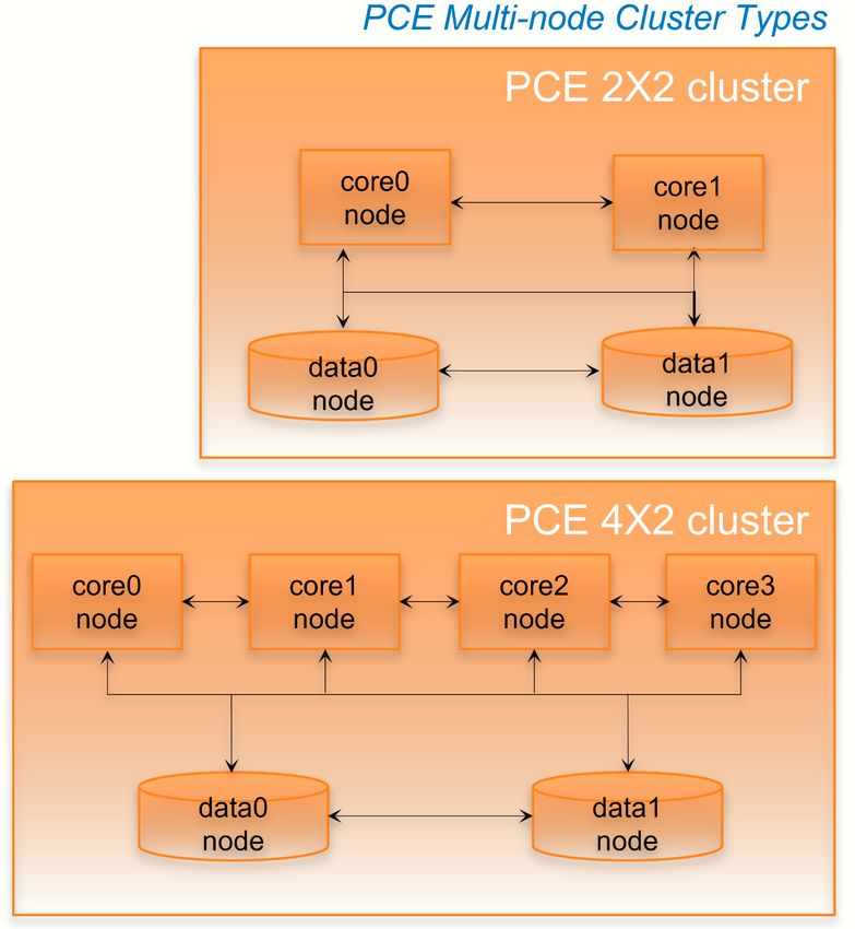
Nodes and Clusters
A PCE node is a single host (server or VM) that runs the PCE. Each node in the cluster
is configured by its node type, which defines its services:
l Core node, known as core0, core1, core2, and core3
l Data node, known as data0 and data1
l Single node in an single-node cluster (SNC), which combines core and data
nodes in one
PCE Installation and Upgrade Guide 20.1.0 7Chapter 1 Overview of PCE Installation
PCE Installation Overview
The total collection of nodes is a PCE cluster. In production, the PCE is typically
deployed as a multiple-node cluster (MNC).
l For smaller deployments where high availability is not necessary, you can deploy
a PCE SNC.
l In a typical PCE deployment, for redundancy, you deploy two instances of each
node type in a PCE 2Xx2 cluster.
l For larger deployments, you can expand the PCE cluster to four core nodes and
two data nodes in a PCE 4x2 cluster.
l To construct a single administrative domain that spans two or more replicating
PCE clusters, deploy a PCE supercluster. See PCE Supercluster Deployment.
Single-node Clusters
In an SNC, some special considerations apply.
PCE Installation and Upgrade Guide 20.1.0 8Chapter 1 Overview of PCE Installation
PCE Installation Overview
Because it contains only a single node, an SNC does not provide high availability (HA)
features. The SNC is a single point of failure. Therefore, Illumio recommends taking
some additional precautionary steps:
l Set up periodic, automated backups.
l Practice restoring from backup to a separate machine (physical or virtual)
before putting the SNC into production use.
l Store a copy of the PCE software installation packages, the PCE database
backup, and the runtime_env.yml file, which stores the PCE's configuration. Store
them on a separate physical machine, preferably in a different datacenter, using
fault tolerant storage.
l If you are running the SNC as a virtual machine, you can make use of the hyper-
visor's high availability and disaster recovery (HA/DR) features.
To prepare for PCE installation on an SNC:
l Have a reserved virtual machine or physical machine ready for the backups of
the PCE software, database, and runtime_env.yml.
l This machine must be able to use the existing IP address of the PCE. Altern-
atively, you can reserve a new IP address for the backup machine, and configure
this IP address in the PCE.
Software Distribution: PCE and UI Packages
Illumio distributes PCE software as two packages: PCE and UI. The PCE package con-
tains the software for the Policy Compute Engine (PCE), and the UI package contains
the PCE web console. You can choose to install these packages separately or
together:
l PCE package plus UI package: This choice is the most common installation scen-
ario. See Installing the PCE and UI.
l PCE package alone: The PCE still serves responses to API calls, but there is no
graphical user interface for display in a browser.
l UI package alone: With this separate package, you can upgrade the UI whenever
you want more recent UI fixes and features, without having to upgrade the
entire PCE. The UI-only installation procedure is much simpler than the full install-
ation. For the UI to work, a compatible version of the PCE must already be
installed. See UI-Only Upgrade.
PCE Installation and Upgrade Guide 20.1.0 9Chapter 2
Prepare for PCE Installation
This chapter contains the following topics:
PCE Installation Planning 10
Requirements for PCE Installation 22
Run ilo-pipgen and ilo-vpngen 37
Before installing the PCE software, be sure to fulfill the prerequisites and do the setup
steps in this section.
PCE Installation Planning
This section describes the decisions you must make and the preparatory tasks you
must do before installing the PCE.
Planning Checklist
The following checklist helps you to plan your PCE installation. Details for each task
are described in later sections.
Prerequisite See section...
Capacity sizing for CPUs, RAM, and storage PCE Capacity Planning
device size and IOPS
PCE storage device partitions PCE Storage Device Partitions
Verify PCE reserved port ranges (for MNCs; Port Ranges for Cluster Com-
does not apply in an SNC) munication
Load balancer setup Load Balancer Requirements
IP address for the PCE PCE IP Address
PCE Installation and Upgrade Guide 20.1.0 10Chapter 2 Prepare for PCE Installation
PCE Installation Planning
Prerequisite See section...
DNS domain name setup DNS Requirements
Mail software SMTP Requirements
TLS setup, including SSL certificate types and l TLS Requirements
settings l Negotiation of TLS Versions for
Communications
l (Optional) Validate and Con-
figure TLS Certificate either
before or after configuring the
PCE
(Optional) SAML IdP SAML IdP
OS package dependencies, libraries, NTP, ipt- OS Setup and Package Depend-
ables, UTF-8, Trusted CA, syslog, process and encies
file limits, and kernel parameters
Configure iptables on PCE hosts Configure iptables on PCE Hosts
with ilo-pipgen
Configure VPN on nodes (for MNCs; does not Enable VPN on PCE Nodes with ilo-
apply in SNC) vpngen
Your full organization name About Your Organization Name
and ID
VEN installation, including planning and pre- VEN Installation and Upgrade
requisites Guide
PCE Capacity Planning
Use these guidelines and requirements to estimate host system capacity based on typ-
ical usage patterns.
The exact requirements vary based on a large number of factors, including, but not lim-
ited to:
l Whether you are using physical or virtual hardware
l Number of managed workloads
l Number of unmanaged workloads and other labeled objects, such as virtual ser-
vices
l Policy complexity, which includes the following factors:
o Number of rules in your rulesets
o Number of labels, IP lists, and other objects in your rules
PCE Installation and Upgrade Guide 20.1.0 11Chapter 2 Prepare for PCE Installation
PCE Installation Planning
o Number of IP ranges in your IP lists
o Number of workloads affected by your rules
l Frequency at which your policies change
l Frequency at which workloads are added or deleted, or workload context
changes, such as, change of IP address
l Volume of traffic flows per second reported to the PCE from all VENs
See the “Maximum Flow Capacity” table for information about maximum flow
capacity of the PCE.
l Total number of unique flows reported to the PCE from all VENs
CPU, Memory, and Storage
The capacity planning tables in this section list minimal and recommended sizes for
CPU, memory, and storage. This section provides two tables, one for physical hard-
ware and one for virtual machines. Use these tables to plan your deployment.
NOTE:
Based on your actual usage and other factors, your capacity needs might
be greater than the recommended sizes. For example, if you have installed
additional software along with the PCE, such as application performance
management (APM) software or an endpoint protection agent, this con-
sumes additional system resources.
Data nodes are configured with a dedicated storage device for each database on the
data nodes. This configuration accommodates growth in traffic data, which is used by
Explorer. See Runtime Parameters for Traffic Datastore on Data Nodes.
For more than 150 IOPS, locally attached, spinning hard disk drives (HDD) are not suf-
ficient. You will require either mixed-use Solid-State Disk (SSD) or Storage Area Net-
work (SAN).
The PCE does not require that you set up swap memory, but it is permissible to enable
swap memory. As long as the PCE nodes are provisioned with the recommended
memory (RAM) as shown in the tables below, the use of swap memory should not
cause any issues.
Physical Hardware
Use this table if you are installing the PCE on physical hardware. If you are using vir-
tual machines, see the table Virtual Hardware.
PCE Installation and Upgrade Guide 20.1.0 12Chapter 2 Prepare for PCE Installation
PCE Installation Planning
Storage Device Size and
MNC Type + Work- Cores/Clock IOPS
RAM per Node
loads/VENs Speed Data
Core Nodes
Nodes
SNC l 2 cores2 8GB A single N/A
Intel® Xeon(R) node includ-
250 VENs1
l
l
CPU E5-2695 ing both
l 2500 work-
v4 at 2.10GHz core and
loads
or equivalent data:
l 1x
50GB4
l 100 IOPS
per
device5
2x2 l 4 cores per 32GB Minimum: Minimum:
node2
l 2,500 VENs1 l Disk: l Disk 1:
Intel® Xeon(R)
50GB3, 4 250GB4
l
l 12,500 work-
CPU E5-2695
loads l 150 IOPS l Disk 2:
v4 at 2.10GHz
per 250GB4
or equivalent
device5 l 600
IOPS
per
device5
2x2 l 16 cores per l Recommended: Minimum: Minimum:
node2, 6 128GB6
l 10,000 VENs1 l Disk: l Disk 1:
Intel® Xeon(R) Minimum: 64GB
50GB3, 4 1TB4
l l
l 50,000 work-
CPU E5-2695
loads l 150 IOPS l Disk 2:
v4 at 2.10GHz
per 1TB4
or equivalent
device5 l 1,800
IOPS
per
device5
4x2 l 16 cores per 128GB6 Minimum: l Disk 1:
node2, 6 1TB4
l 25,000 VENs1 l Disk:
Intel® Xeon(R) Disk 2:
50GB3, 4
l l
l 125,000 work-
CPU E5-2695 1TB4
PCE Installation and Upgrade Guide 20.1.0 13Chapter 2 Prepare for PCE Installation
PCE Installation Planning
Storage Device Size and
MNC Type + Work- Cores/Clock IOPS
RAM per Node
loads/VENs Speed Data
Core Nodes
Nodes
loads v4 at 2.10GHz l 150 IOPS l 5,000
or equivalent. per IOPS
device5 per
device5
Footnotes:
1Number of VENs/workloads is the sum of both the number of managed VENs and
the number of unmanaged workloads.
2 CPUs:
l The recommended number of cores is based only on physical cores from alloc-
ated CPUs, irrespective of hyper-threading.
3 This is the absolute minimum needed. In the future, other applications, support
reports, or new features may require additional disk.
4 Additional disk notes:
l Storage requirements for network traffic data can increase rapidly as the
amount of network traffic increases.
l Network File Systems (NFS) is not supported for Illumio directories specified in
runtime; for example, data_dir, persistent_data_dir, ephemeral_data_dir.
5 Input/output operations per second (IOPS) are based on 8K random write oper-
ations. IOPS specified for an average of 300 flow summaries (80% unique src_ip,
dest_ip, dest_port, proto) per workload every 10 minutes. Different traffic profiles might
require higher IOPS.
6 In the case of fresh installs or upgrades of a 2x2 for 10,000 VENs or a 4x2 for 25,000
VENs, if you deploy a system without sufficient cores, memory, or both, then the PCE
will automatically reduce the object limits to 2,500 workloads. Object limit is the num-
ber of VENs (agents) per PCE. Adding more than 2,500 workloads will fail and an
event is logged indicating that object limits have been exceeded. The workaround is
to increase the number of cores, memory, or both to the recommended specifications
and then increase the object limits manually. See PCE Default Object Limits in the
PCE Administration Guide.
PCE Installation and Upgrade Guide 20.1.0 14Chapter 2 Prepare for PCE Installation
PCE Installation Planning
Virtual Hardware
Use this table if you are installing the PCE on virtual machines. If you are using phys-
ical hardware, see the table Physical Hardware.
Storage Device Size and
MNC Type + Work- Virtual Cores/C- IOPS
RAM per Node
loads/VENs lock Speed Data
Core Nodes
Nodes
SNC l 4 virtual 8GB7 Minimum: N/A
cores
l 250 VENs1 l Disk: 50GB
(vCPU)2 3, 4
l 2500 work-
l Intel® Xeon
loads l 150 IOPS
(R) CPU E5-
per device5
2695 v4 at
2.10GHz or
higher
2x2 l 8 virtual 32GB7 Minimum: Minimum:
cores
l 2,500 VENs1 l Disk: l Disk 1:
(vCPU) per
12,500 work- 50GB3, 4 250GB
node2
l
loads l 150 IOPS l Disk 2:
l Intel® Xeon
per device5 250GB
(R) CPU E5-
l 600
2695 v4 at
IOPS
2.10GHz or
per
higher
device
2x2 l 32 virtual l Recommended: Minimum: Minimum:
cores 128GB6, 7
l 10,000 VENs1 l Disk: l Disk 1:
(vCPU) per Minimum: 64GB
50GB3, 4 1TB4
l
50,000 work-
node2, 6
l
loads l 150 IOPS l Disk 2:
l Intel® Xeon
per device5 1TB4
(R) CPU E5-
l 1,800
2695 v4 at
IOPS
2.10GHz or
per
higher
device5
4x2 l 32 virtual 128GB6, 7 Minimum: l Disk 1:
cores 1TB4
l 25,000 VENs1 l Disk:
PCE Installation and Upgrade Guide 20.1.0 15Chapter 2 Prepare for PCE Installation
PCE Installation Planning
Storage Device Size and
MNC Type + Work- Virtual Cores/C- IOPS
RAM per Node
loads/VENs lock Speed Data
Core Nodes
Nodes
l 125,000 work- (vCPU) per 50GB3, 4 l Disk 2:
loads node2, 6 l 150 IOPS 1TB4
l Intel® Xeon per device5 l 5,000
(R) CPU E5- IOPS
2695 v4 at per
2.10GHz or device5
higher
Footnotes:
1Number of VENs/workloads is the sum of both the number of managed VENs and
the number of unmanaged workloads.
2 Full reservations for vCPU. No overcommit.
3 This is the absolute minimum needed. In the future, other applications, support
reports, or new features may require additional disk.
4 Additional disk notes:
l Storage requirements for network traffic data can increase rapidly as the
amount of network traffic increases.
l Network File Systems (NFS) is not supported for Illumio directories specified in
runtime; for example, data_dir, persistent_data_dir, ephemeral_data_dir.
5 Input/output operations per second (IOPS) are based on 8K random write oper-
ations. IOPS specified for an average of 300 flow summaries (80% unique src_ip,
dest_ip, dest_port, proto) per workload every 10 minutes. Different traffic profiles might
require higher IOPS.
6 In the case of fresh installs or upgrades of a 2x2 for 10,000 VENs or a 4x2 for 25,000
VENs, if you deploy a system without sufficient cores, memory, or both, then the PCE
will automatically reduce the object limits to 2,500 workloads. Object limit is the num-
ber of VENs (agents) per PCE. Adding more than 2,500 workloads will fail and an
event is logged indicating that object limits have been exceeded. The workaround is
to increase the number of cores, memory, or both to the recommended specifications
and then increase the object limits manually. See PCE Default Object Limits in the
PCE Administration Guide.
7 Full reservations for vRAM. No overcommit.
PCE Installation and Upgrade Guide 20.1.0 16Chapter 2 Prepare for PCE Installation
PCE Installation Planning
Maximum Flow Capacity
The following table shows the maximum capacity of the PCE to accept flow data from
all VENs.
Flow Rate Equivalent Flow Rate
MNC Type + Workloads/VENs
(flow-summaries/second) (flows/second)2
SNC 100 1,030
l 250 VENs
l 2500 workloads
2x2 1,000 10,300
l 2,500 VENs
l 12,500 workloads
2x2 4,100 422,000
l 10,000 VENs
l 50,000 workloads
4x2 10,4001 1,070,000
l 25,000 VENs
l 125,000 workloads
Footnotes:
1The PCE might need to be tuned to achieve this rate. If you need to tune the PCE,
please contact Illumio Support for assistance.
2 Real-world observation shows that 102 flows result in one flow summary on average.
PCE Storage Device Partitions
PCE Storage Device Layout
You should create separate storage device partitions to reserve the amount of space
specified below. These recommendations are based on PCE Capacity Planning.
The values given in these recommendation tables are guidelines based on testing in
Illumio’s labs. If you wish to deviate from these recommendations based on your own
platform standards, please first contact your Illumio support representative for advice
and approval.
PCE Installation and Upgrade Guide 20.1.0 17Chapter 2 Prepare for PCE Installation
PCE Installation Planning
PCE Single-Node Cluster for 250 VENs
Size to
Storage Partition Node
Alloc- Notes
Device mount point Types
ate
Device / 8GB Core, The size of this partition assumes the sys-
1, Par- Data tem temporary files are stored in /tmp
tition A and core dump file size is set to zero. The
PCE installation occupies approximately
500MB of this space.
Device /var/log 16GB Core, The size of this partition assumes that
1, Par- Data PCE application logs and system logs are
tition B both stored in /var/log. PCE application
logs are stored in the /var/log/illumio-pce
directory. The recommended size
assumes average use by the OS with com-
mon packages installed and logging levels
set to system defaults. Log size limits are
configurable, so your system may require
more or less log space. To find the poten-
tial maximum disk space required for your
logs, use this command:
$ sudo -u ilo-pce illumio-pce-env logs
--diag
Device /var/lib/il- Balance Core, The size of this partition assumes that
1, Par- lumio-pce of Data Core nodes use local storage for applic-
tition C Device ation code in /var/lib/illumio-pce, and
1 also assumes that PCE support report
files, and other temporary (ephemeral)
files, etc., are stored in /var/lib/illumio-
pce/tmp.
PCE 2x2 Multi-Node Cluster for 2,500 VENs
Storage Partition mount Size to Node
Notes
Device point Allocate Types
Device 1, Par- / 16GB Core, The size of this partition
tition A Data assumes the system tem-
porary files are stored in /tmp
PCE Installation and Upgrade Guide 20.1.0 18Chapter 2 Prepare for PCE Installation
PCE Installation Planning
Storage Partition mount Size to Node
Notes
Device point Allocate Types
and core dump file size is set
to zero.
Device 1, Par- /var/log 32GB Core, The size of this partition
tition B Data assumes that PCE application
logs and system logs are both
stored in /var/log.
PCE application logs are
stored in the /var/log/illumio-
pce directory.
Device 1, Par- /var/lib/illumio- Balance Core, The size of this partition
tition C pce of Device Data assumes that Core nodes use
1 local storage for application
code in /var/lib/illumio-pce,
and also assumes that PCE
support report files, and other
temporary (ephemeral) files,
etc. are stored in /var/lib/il-
lumio-pce/tmp.
Device 2, /var/lib/illumio- All of Data For network traffic data in a
Single par- pce/data/Explorer Device 2 two-storage-device con-
tition. (250GB) figuration for the data nodes,
Applicable in it should be a separate device
a two-stor- that is mounted on this dir-
age-device ectory.
configuration Set the runtime_emv.yml to
data_dir: /var/lib/illumio-
pce/data/Explorer, which will
automatically create a sub-
directory called
/var/lib/illumio-pce/data/Ex-
plorer/traffic_datastore
The partition mount point and
the runtime setting must
match. If you customize the
mount point, make sure that
PCE Installation and Upgrade Guide 20.1.0 19Chapter 2 Prepare for PCE Installation
PCE Installation Planning
Storage Partition mount Size to Node
Notes
Device point Allocate Types
you also change the runtime
setting accordingly.
PCE 2x2 Multi-Node Cluster for 10,000 VENs and
PCE 4x2 Multi-Node Cluster for 25,000 VENs
Storage Partition mount Size to Node
Notes
Device point Allocate Types
Device 1, Par- / 16GB Core, The size of this partition
tition A Data assumes the system tem-
porary files are stored in /tmp
and core dump file size is set
to zero.
Device 1, Par- /var/log 32GB Core, The size of this partition
tition B Data assumes that PCE application
logs and system logs are both
stored in /var/log.
PCE application logs are
stored in the /var/log/illumio-
pce directory.
Device 1, Par- /var/lib/illumio- Balance Core, The size of this partition
tition C pce of Device Data assumes that Core nodes use
1 local storage for application
code in /var/lib/illumio-pce,
and also assumes that PCE
support report files, and other
temporary (ephemeral) files,
etc. are stored in /var/lib/il-
lumio-pce/tmp.
Device 2, /var/lib/illumio- All of Data For network traffic data in a
Single Par- pce/data/traffic Device 2 two-storage-device con-
tition (1TB) figuration for the data nodes,
Applicable in it should be a separate device
a two-stor- that is mounted on this dir-
age-device ectory.
configuration In runtime_env.yml, set the
PCE Installation and Upgrade Guide 20.1.0 20Chapter 2 Prepare for PCE Installation
PCE Installation Planning
Storage Partition mount Size to Node
Notes
Device point Allocate Types
traffic_datastore : data_dir
parameter to match the value
of the partition mount point
(see previous column) as fol-
lows: traffic_datastore: data_
dir: /var/lib/illumio-
pce/data/traffic.
The partition mount point and
the runtime setting must
match. If you customize the
mount point, make sure that
you also change the runtime
setting accordingly.
Runtime Parameters for Traffic Datastore on Data Nodes
For the traffic datastore, set the following parameters in runtime_env.yml:
traffic_datastore:
data_dir: path_to_second_disk (e.g. /var/lib/illumio-pce/data/traffic)
max_disk_usage_gb: Set this parameter according to the table below.
partition_fraction: Set this parameter according to the table below.
The recommended values for the above parameters, based on PCE node cluster type
and estimated number of workloads (VENs), are as follows:
2x2 | 2x2 | 4x2 |
Setting 2,500 10,000 25,000 Note
VENs VENs VENs
traffic_data- 100 400 GB 400 GB This size reflects only part of the
store:max_disk_usage_ GB required total size, as detailed in
gb PCE Capacity Planning.
The remaining disk capacity is
needed for database internals and
data migration during upgrades.
traffic_data- 0.5 0.5 0.5
store:partition_frac-
tion
PCE Installation and Upgrade Guide 20.1.0 21Chapter 2 Prepare for PCE Installation
Requirements for PCE Installation
For additional ways to avoid disk capacity issues, see Manage Data and Disk Capacity
in the PCE Administration Guide.
Port Ranges for Cluster Communication
(For MNC; does not apply in SNC.)
The following port ranges are needed for communications between the PCE cluster
nodes.
Protocols Port Range
TCP 3100 to 3600
TCP 5100 to 6300
TCP and UDP 8000 to 8400
TCP 11200 to 11300
TCP and UDP 24200 to 24300
Requirements for PCE Installation
Before installing the PCE, be sure your underlying systems are sufficient to suc-
cessfully install and run the PCE. Check all the following system requirements.
Load Balancer Requirements
For MNC; does not apply in a SNC.
A server load balancer or DNS-level load balancer is required to distribute traffic to
the PCE core nodes.
Configure the load balancer to use the Illumio REST API to monitor which cluster core
nodes are available to receive requests. See the REST API Developer Guide for exact
usage.
GET [api_version]/node_available
No authentication is required to call this API. An HTTP status code of 200 means the
node is able to receive requests. Any other status code or no response means the
node is unable accept requests. Unhealthy or unresponsive nodes should be removed
from the load balancing pool.
l The PCE Health Check API can experience up to a 30-second delay to return the
actual status of the node.
PCE Installation and Upgrade Guide 20.1.0 22Chapter 2 Prepare for PCE Installation
Requirements for PCE Installation
l In the 4x2 configuration, a maximum of two core nodes are available (return a
status code of 200) at any time.
l When using a DNS load balancer, it should only serve IP addresses for the cluster
FQDN of those nodes that respond with a 200 to the /node_available API. For
rapid failover in the event of a core node failure, Illumio recommends a DNS TTL
of between 30 and 60 seconds.
PCE IP Address
Illumio recommends a statically-assigned IP address. By default, the PCE auto-
matically uses the first available private IP address on the node. The PCE does not
automatically bind to a public IP address.
When you use a public IP address or the node has multiple interfaces, you need to con-
figure the PCE with the interface you want to use. To do so, set internal_service_ip in
the configuration file runtime_env.yml. For example:
internal_service_ip: 10.2.8.89
To configure networking, see your OS vendor's documentation on the ifcfg-ethN
script.
DNS Requirements
Your Domain Name System (DNS) must resolve the PCE's fully qualified domain name
(FQDN). The FQDN must be resolvable on all managed workloads, on all nodes in the
PCE cluster, and for all users of the PCE web console and REST API.
If you are using DNS-level load balancing, the PCE FQDN should resolve to the IP
addresses of the core nodes. If you are using a server load balancer, the PCE FQDN
should resolve to the VIPs of the server load balancer.
SMTP Requirements
An SMTP relay is required to send user invitations and “forgot password” email replies
from the PCE.
The SMTP configuration parameter during PCE installation is smtp_relay_address. Allow-
able values are either an IP address with its SMTP port (default 587) or a resolvable
FQDN with the SMTP port.
PCE Installation and Upgrade Guide 20.1.0 23Chapter 2 Prepare for PCE Installation
Requirements for PCE Installation
TLS Requirements
PCE communication is secured using the Transport Layer Security (TLS) protocol, the
successor to the deprecated Secure Sockets Layer (SSL) protocol. TLS is used for
securing the following communication sessions:
l User access to the PCE web console and REST API over the HTTPS protocol.
l Communication between the PCE and VENs.
VEN-to-PCE communications for the EventService (default is port 8444) are
secured by the ECDHE suite of cryptographic ciphers, which use an elliptic curve
Diffie-Hellman key exchange. This exchange is signed with RSA signature
algorithms.
l Communication between PCE nodes in a multi-node cluster.
If you want to generate a temporary, self-signed certificate, see Understanding Illumio
Trial Certificates in the Knowledge Base (log in required).
For an in-depth discussion of deploying the PCE with TLS, see Preparing Certificates
for a PCE deployment in the Knowledge Base (log in required).
X.509 Certificate
An X.509 server certificate must be installed on each PCE node during installation.
When any client (the VEN) opens a TLS session to the PCE (for example, pairing a
workload, accessing the PCE web console, retrieving updated policy), the PCE
presents the server certificate to secure the communication. The server certificate is
uploaded as part of a certificate bundle that contains the server certificate and the
chain of CA certificates (Intermediate or Root) to establish the chain of trust back to a
Root CA.
CAUTION:
The client must be able to validate the chain of trust back to the Root CA
for this certificate; otherwise, the TLS handshake fails. You might need to
add all the certificates in the chain of trust to the keychain of the client.
The certificate package for the Illumio PCE must meet the following basic criteria:
l The file must contain PEM-encoded certificates.
l The certificate's signature algorithm must be SHA256WithRSAEncryption.
l The certificate's signature algorithm must not be RSASSA-PSS.
PCE Installation and Upgrade Guide 20.1.0 24Chapter 2 Prepare for PCE Installation
Requirements for PCE Installation
l The file must contain the server certificate and the entire certificate chain neces-
sary to establish the chain of trust back to a Root CA.
a. The package must include all of the CA certificates (Intermediate and/or
Root) needed to establish the chain of trust back to a Root CA.
o If the certificate is generated by a Private CA, all certificates in the
chain of trust back to the Root CA must be included. This includes the
Root CA certificate and any applicable Intermediate CA certificates.
o If the certificate is generated by a major Public CA (such as, VeriSign,
GeoTrust, Entrust, or Thawte), any Intermediate CA certificates
needed to establish the chain of trust back to the Public Root CA
must be included.
b. Pay careful attention to the order of the certificates in the bundle. The
server certificate must be first. If you have an Apache-style bundle gen-
erated by a standard certificate request process, you need to open the file
in a text editor and reverse the order of the certificates. Apache always
expects the root certificate to come first, then any intermediates in order
(from the root down), and the server certificate is last. The PCE uses nginx,
which expects the opposite order. For additional details, see the Nginx doc-
umentation.
The certificate bundle should look something like this:
-----BEGIN CERTIFICATE-----
-----END CERTIFICATE-----
-----BEGIN CERTIFICATE-----
-----END CERTIFICATE-----
-----BEGIN CERTIFICATE-----
-----END CERTIFICATE-----
l All certificates in the bundle must be valid for the current date, which depends
on the system time being set correctly.
l A trusted root store must be available for OpenSSL to validate certificates.
l The certificate must match the PCE FQDN, which can be an exact match (for
example, pce.mycompany.com) or a wildcard match (for example, *.
mycompany.com)
PCE Installation and Upgrade Guide 20.1.0 25Chapter 2 Prepare for PCE Installation
Requirements for PCE Installation
The certificate must support both Server and Client authentication. Client authen-
tication is used between nodes in an MNC. Run the following command and verify TLS
Web Server Authentication, TLS Web Client Authentication appears within the X509v3
Extended Key Usage section.
$ openssl x509 -text -noout -in pce.mycompany.com.bundle.crt
...
X509v3 Extended Key Usage:
TLS Web Server Authentication, TLS Web Client Authentication
...
RSASSA-PSS Signature Algorithm Not Supported
The certificate signature algorithm RSASSA-PSS, which is based on PKCS 1 version 2.1,
is not supported, because it cannot be validated. This limitation is a widely known
problem with this signature algorithm.
The PCE certificate requires the SHA256WithRSEencryption signature.
CAUTION:
If you use Microsoft Certificate Authority (CA) to sign PCE certificates,
make sure to use the SHA256WithRSEencryption. PKCS#1 version 2.1 is
enabled by default on Microsoft CAs and produces the unsupported
RSASSA-PSS signature algorithm.
Private Keys
The private key that matches the X.509 certificate must be installed on each PCE
node during installation, and the following guidelines must be met:
l The private key must be PEM-encoded.
l The file must not be encoded.
l The file must not be password protected.
Negotiation of TLS Versions for Communications
The PCE negotiates the use of Transport Layer Security (TLS) versions 1.0, 1.1 or 1.2 for
VEN-to-PCE communications, the PCE's web server for the PCE web console, and the
REST API. The PCE selects the highest version that the your workloads support.
l The PCE default minimum version is TLS 1.0.
l For VEN versions 18.1 and later, all VENs use TLS 1.2.
PCE Installation and Upgrade Guide 20.1.0 26Chapter 2 Prepare for PCE Installation
Requirements for PCE Installation
l SUSE VEN version 17.1.x requires minimum version TLS 1.0
l Windows Server 2008 R2 SP1: The HTTP Client library, WinHttp, does not have
the necessary API to limit SSL negotiation only to TLS 1.2. This must be con-
figured through the Registry. See the Microsoft Support article “Update to
enable TLS 1.1 and TLS 1.2.”
Changing Default TLS version
Except for VEN 17.1 for SUSE, which requires TLS 1.0, you can use TLS 1.0, 1.1 or 1.2 with
any version of the VEN. In addition, you should verify that any browser you use is cap-
able of negotiating the minimum version you set.
If you want to change the minimum TLS version, edit the following parameter in
runtime_env.yml:
min_tls_version
The value of min_tls_version configures the PCE front end ports in runtime_env.yml:
l front_end_https_port (default 8443)
l front_end_https_management_port (defaults to front_end_https_port)
l front_end_event_service_port (default 8444)
Allowable values:
l tls1_0 allows TLS 1.0, 1.1, and 1.2.
l tls1_1 allows TLS 1.1 and 1.2.
l tls1_2 allows only TLS 1.2.
(Optional) Configure SAML IdP for User Login
After installation, you can configure the PCE to rely on an external, third-party SAML
identity provider system. See Single Sign-on Configuration in the PCE Administration
Guide. The guide has step-by-step details for a wide variety of IdPs.
OS Setup and Package Dependencies
For information, see PCE OS Support and Package Dependencies on the Illumio Sup-
port portal.
NTP
Set up a Network Time Protocol (NTP) client for time synchronization.
To install and configure NTP, run the following commands:
PCE Installation and Upgrade Guide 20.1.0 27Chapter 2 Prepare for PCE Installation
Requirements for PCE Installation
# yum install ntp # Install ntp module
# date # Verify that the timezone is set correctly. If wrong, fix the
timezone with timedatectl set-timezone
# systemctl enable ntpd # Set NTP to start at boot
# service start ntpd # Start the ntpd daemon
# chkconfig ntpd on # Verify the ntpd daemon configuration
IPTables
For the initial installation, you should disable iptables.
If iptables is enabled, you must configure it to allow inbound HTTPS connections to
the PCE core nodes and service ports.
# service iptables stop
# On CentOS 7.x, use the systemctl stop firewalld command.
# chkconfig iptables off
Language: UTF-8
Set the system language to a UTF-8 variant of English: either en_US.UTF-8 or en_GB.UTF-
8.
Set the variable LANG="en_US.UTF-8" or LANG="en_GB.UTF-8" in the following files:
l RHEL 6: /etc/sysconfig/i18n
l RHEL 7: /etc/locale.conf
Trusted Public CA Store
A trusted root public Certificate Authority (CA) store must be available for OpenSSL
to validate certificates.
If you rely on a certificate signed by a public CA, be sure to install the latest public
root CA certificates ca-certificates package.
# yum install ca-certificates
When your certificate is signed by a private CA or the signing CAs are already
included in each node's trusted root CA store, the ca-certificates package is not
required.
PCE Installation and Upgrade Guide 20.1.0 28Chapter 2 Prepare for PCE Installation
Requirements for PCE Installation
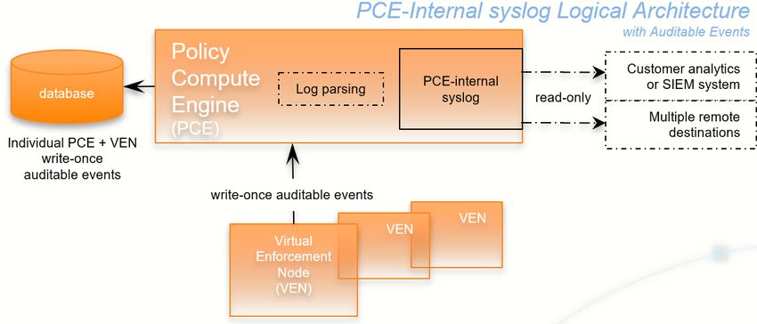
PCE Internal Syslog
The PCE comes with an internal syslog configuration. The purpose of the PCE internal
syslog is to help organizations use syslog without installing it themselves. See
(Optional) Configure PCE Internal Syslog.
Process and File Limits and Kernel Parameters
This section describes how to set the process and file limits and OS kernel parameters
that are required for PCE operation. The approach is different depending on whether
you are configuring an SNC or MNC, and which operating system you are using, so
look for the appropriate sections in the discussion that follows.
Three categories of settings must be configured:
l Process and file limits
l OS kernel parameters
l Kernel module tuning
WARNING:The parameter modifications described in this section are strict
requirements and must be followed to ensure proper functionality of Illu-
mio Core. If an Illumio support case is opened, and analysis finds that these
parameters are not met, you will be directed to meet these requirements
before any additional troubleshooting can be performed.
Keep the following in mind when managing these parameters:
l Root access is needed for many of these procedures. Befor you start, be sure
you have login credentials for a user account with root permissions.
l When your settings are already greater than these, you do not need to reduce
them to these values.
l Make sure you do not have any automated processes that change these values.
SNC Process and File Limits and OS Kernel Parameters
The following table shows the required process and file limits for single-node clusters.
To set these values, see Set and Verify Process and File Limits.
Parameter Value
core (hard) 0
core (soft) 0
nofile (hard)1 65535
PCE Installation and Upgrade Guide 20.1.0 29Chapter 2 Prepare for PCE Installation
Requirements for PCE Installation
Parameter Value
nofile (soft)1 65535
nproc (hard) 65535
nproc (soft) 65535
1When you run additional processes on the PCE, such as monitoring or other oper-
ations processes, you might need to increase the value of nofile.
The following table shows the required OS kernel parameter values for single-node
clusters. To set these values, see Set and Verify OS Kernel Parameters.
Parameter Value
fs.file-max 2000000
net.core.somaxconn 16384
kernel.shmmax 60000000
vm.overcommit_memory 1
nf_conntrack_max 1048576
The following table shows the required SNC kernel module tuning. To set this value,
see Tune the Kernel Module.
Parameter Value
nf_conntrack hashsize 262144
MNC Process and File Limits and OS Kernel Parameters
The following table shows the required process and file limits for multi-node clusters.
To set these values, see Set and Verify Process and File Limits.
Parameter Core Nodes Data Nodes
core (hard) 0 0
core (soft) 0 0
nofile (hard)1 65535 65535
nofile (soft)1 65535 65535
nproc (hard) 65535 65535
nproc (soft) 65535 65535
The following table shows the required OS kernel parameter values for multi-node
clusters. To set these values, see Set and Verify OS Kernel Parameters.
Parameter Core Nodes Data Nodes
fs.file-max 2000000 2000000
PCE Installation and Upgrade Guide 20.1.0 30Chapter 2 Prepare for PCE Installation
Requirements for PCE Installation
Parameter Core Nodes Data Nodes
net.core.somaxconn 16384 Use system default setting
kernel.shmmax Use system default setting 60000000
vm.overcommit_memory Use system default setting 1
nf_conntrack_max 1048576 Use system default setting
The following table shows the required kernel module tuning. To set this value, see
Tune the Kernel Module.
Parameter Core Nodes
nf_conntrack hashsize 262144
Set and Verify Process and File Limits
Process and file limits are set by editing configuration files and issuing commands. The
techniques vary depending on the operating system version and which system man-
agement daemon you are using, systemd or init.d. If you are not sure which system
management daemon is being used, run the following command:
$ ps -p1 | grep "init|upstart|systemd"
CentOS 7.x or RHEL 7.x with systemd
On every core and data node, do the following steps:
1. As root, edit the following Illumio-specific configuration file:
/etc/systemd/system/illumio-pce.service.d/override.conf
2. Place the following lines in the file.:
[Service]
LimitCORE=0
LimitNOFILE=65535
LimitNPROC=65535
3. Reload the daemon configuration and restart the service to apply the change:
# systemctl daemon-reload
# systemctl restart illumio-pce.service
4. Verify that the correct settings are now in effect. As the PCE runtime user, run
the following command. Verify that the output is as shown:
PCE Installation and Upgrade Guide 20.1.0 31Chapter 2 Prepare for PCE Installation
Requirements for PCE Installation
$ sudo -u ilo-pce systemctl show illumio-pce.service | egrep
"LimitCORE|LimitNPROC|LimitNOFILE"
LimitCORE=0
LimitNOFILE=65535
LimitNPROC=65535
See also the Linux systemd man page, especially "Table 1. Resource limit directives."
CentOS 7.x or RHEL 7.x with init.d
On every core and data node, do the following steps:
1. As root, edit the following Illumio-specific configuration file:
/etc/security/limits.d/99-illumio.conf
2. Place the following lines in the file. The ilo-pce on each line indicates that the lim-
its apply to only the PCE runtime user, which is ilo-pce unless this default user
name was overridden during PCE installation. If you want the limits to apply to
all users, use asterisks (*) instead of ilo-pce.
ilo-pce soft core 0
ilo-pce hard core 0
ilo-pce soft nofile 65535
ilo-pce hard nofile 65535
ilo-pce soft nproc 65535
ilo-pce hard nproc 65535
3. Apply the change:
# sysctl -p /etc/security/limits.d/99-illumio.conf
4. Verify that the correct settings are now in effect. As the PCE runtime user, run
the following commands. Verify that the output is as shown:
$ sudo -u ilo-pce ulimit -n
65535
$ sudo -u ilo-pce ulimit -u
65535
PCE Installation and Upgrade Guide 20.1.0 32Chapter 2 Prepare for PCE Installation
Requirements for PCE Installation
$ sudo -u ilo-pce ulimit -c
0
CentOS 6.x or RHEL 6.x
On every core and data node, do the following steps:
1. As root, edit the following Illumio-specific configuration file:
/etc/security/limits.d/99-illumio.conf
2. Place the following lines in the file. The ilo-pce on each line indicates that the lim-
its apply to only the PCE runtime user, which is ilo-pce unless this default user
name was overridden during PCE installation. If you want the limits to apply to
all users, use asterisks (*) instead of ilo-pce.
ilo-pce soft core 0
ilo-pce hard core 0
ilo-pce soft nofile 65535
ilo-pce hard nofile 65535
ilo-pce soft nproc 65535
ilo-pce hard nproc 65535
3. Apply the change:
# sysctl -p /etc/security/limits.d/99-illumio.conf
4. Verify that the correct settings are now in effect. As the PCE runtime user, run
the following commands. Verify that the output is as shown:
$ sudo -u ilo-pce ulimit -n
65535
$ sudo -u ilo-pce ulimit -u
65535
$ sudo -u ilo-pce ulimit -c
0
PCE Installation and Upgrade Guide 20.1.0 33Chapter 2 Prepare for PCE Installation
Requirements for PCE Installation
WARNING:Be sure there are no additional configuration files in /etc/se-
curity/limits.d that might override the recommended limits.
Set and Verify OS Kernel Parameters
Kernel parameters are set by editing configuration files and issuing commands. The
commands are the same on all PCE-supported versions of CentOS and RHEL, but the
techniques vary depending on whether you are configuring an SNC or MNC.
SNC: Set and verify OS kernel parameters
1. As root, edit the following Illumio-specific configuration file:
/etc/sysctl.d/99-illumio.conf
2. Place the following lines in the file:
fs.file-max = 2000000
kernel.shmmax = 60000000
vm.overcommit_memory = 1
net.core.somaxconn = 16384
net.nf_conntrack_max = 1048576
3. Apply the settings:
# sysctl -p /etc/sysctl.d/99-illumio.conf
4. Verify that the correct settings are now in effect. As the PCE runtime user, run
the following command. Verify that the output is as shown:
$ sudo -u ilo-pce sysctl -a 2>/dev/null | egrep "fs.file-
max|kernel.shmmax|vm.overcommit_memory|net.core.somaxconn|net.nf_conntrack_
max"
fs.file-max = 2000000
kernel.shmmax = 60000000
net.core.somaxconn = 16384
net.nf_conntrack_max = 1048576
vm.overcommit_memory = 1
For more information, see Configuring Kernel Parameters at Runtime in the Red Hat
documentation.
MNC: Set and verify OS kernel parameters
PCE Installation and Upgrade Guide 20.1.0 34Chapter 2 Prepare for PCE Installation
Requirements for PCE Installation
1. As root, on each core node, edit /etc/sysctl.d/99-illumio.conf and add the fol-
lowing lines:
fs.file-max = 2000000
net.core.somaxconn = 16384
net.nf_conntrack_max = 1048576
2. As you go, on each core node, apply the settings:
# sysctl -p /etc/sysctl.d/99-illumio.conf
3. As root, on each data node, edit /etc/sysctl.d/99-illumio.conf and add the fol-
lowing lines:
fs.file-max = 2000000
kernel.shmmax = 60000000
vm.overcommit_memory = 1
4. As you go, on each data node, apply the settings:
# sysctl -p /etc/sysctl.d/99-illumio.conf
5. Verify that the correct settings are now in effect. As the PCE runtime user, run
the following command. Verify that the output is as shown:
$ sudo -u ilo-pce sysctl -a 2>/dev/null | egrep "fs.file-
max|kernel.shmmax|vm.overcommit_memory|net.core.somaxconn|net.nf_conntrack_
max"
fs.file-max = 2000000
kernel.shmmax = 60000000
net.core.somaxconn = 16384
net.nf_conntrack_max = 1048576
vm.overcommit_memory = 1
For more information, see Configuring Kernel Parameters at Runtime in the Red Hat
documentation.
PCE Installation and Upgrade Guide 20.1.0 35Chapter 2 Prepare for PCE Installation
Requirements for PCE Installation
Tune the Kernel Module
Adjust the hash size setting for the kernel conntrack module as follows. For this set-
ting, the commands are the same on all PCE-supported versions of CentOS and RHEL.
On all core nodes:
1. As root, run the following commands to tune the kernel conntrack module. The
commands take effect immediately.
# modprobe nf_conntrack
# echo 262144 > /sys/module/nf_conntrack/parameters/hashsize
2. Run the following command to apply the same setting automatically on reboot:
# echo "options nf_conntrack hashsize=262144" > /etc/modprobe.d/illumio.conf
3. Verify that the correct setting is now in effect. Run the following command to
inspect the hash size. Verify that the output is as shown:
# cat /sys/module/nf_conntrack/parameters/hashsize
262144
About Your Organization Name and ID
An organization is a group of policies and users in Illumio Core. An organization can
contain any number of users, workloads, and policy objects (rulesets, IP lists, services,
and security settings). When you sign up with Illumio, you will receive an email invit-
ation to create your company's organization in Illumio Core.
Have ready your full organization name, which you specify at installation.
For on-premise PCE deployments, installation creates an organization identifier (org
ID) and assigns the value of 1 to org ID. The value 1 distinguishes your on-premises
PCE from the Illumio Secure Cloud (SaaS) service, where each customer has a unique
org ID.
The org ID is needed with the Illumio Core REST API, where you set org-ID to 1 for the
on-premises PCE, and for other purposes.
PCE Installation and Upgrade Guide 20.1.0 36Chapter 2 Prepare for PCE Installation
Run ilo-pipgen and ilo-vpngen
Run ilo-pipgen and ilo-vpngen
Illumio provides two utilities that configure the PCE's environment for additional secur-
ity: ilo-pipgen and ilo-vpngen. Running these two utilities is a prerequisite before
installing the PCE.
Configure iptables on PCE Hosts with ilo-pipgen
When the PCE is installed on-premises, the deployment has several connections
between PCE components running on different nodes. PCE components listen for con-
nections on TCP and UDP ports in specific ranges (see Port Ranges for Cluster Com-
munication). All PCE nodes must be able to communicate with each other, but no
other inbound connections should be accepted to ports in these ranges. Use the ilo-
pipgen utility to make sure that inbound connections to PCE components are per-
mitted only from other PCE hosts, and not from external sources. This utility generates
an iptables configuration that blocks inbound connections on the port ranges used by
the PCE. Inbound connections on other ports are unaffected, and all outbound con-
nections are permitted by default.
When the iptables firewall is already in use, any existing rules are overwritten. You will
have an opportunity to import any locally-defined rules before applying the new ipt-
ables configuration.
Prerequisites
l Download the ilo-pipgen script from Configuring iptables on PCE hosts with ilo-
pipgen in the Illumio Knowledge Base (log in required)
l Root access on all PCE nodes is required.
l The iptables firewall must be managed using iptables-services. CentOS and
RHEL 7 users with firewalld must disable firewalld and switch to iptables-ser-
vices using the following commands:
# yum install -y iptables-services # or install from an alternate location as
necessary
# systemctl mask --now firewalld
# systemctl enable iptables ip6tables
PCE Installation and Upgrade Guide 20.1.0 37Chapter 2 Prepare for PCE Installation
Run ilo-pipgen and ilo-vpngen
Deploy ilo-pipgen
1. On the core0 node only, generate the iptables configuration:
a. Make the directory /var/tmp/illumio-pipgen.
b. Copy the script ilo-pipgen to this directory.
c. Use the following command to make sure the script is executable:
chmod a+x /var/tmp/illumio-pipgen/ilo-pipgen
d. Create a plain text file ip_addrs_input.txt containing the IP addresses of all
PCE nodes in your cluster or Supercluster, one IP address per line. A 2x2
MNC should have four IP addresses; a 4x2 MNC should have six IP
addresses; and a Supercluster should have more, depending on the num-
ber of clusters.
o When running in AWS, do not include the public IP addresses of the
nodes (only use the private IP addresses).
o When the PCE cluster is part of a Supercluster, include all addresses
of all PCE nodes in all regions of your Supercluster.
o When the PCE is deployed as an SNC, include only the single IP
address of the PCE node.
Example ip_addrs_input.txt addresses:
10.1.2.1
10.1.2.2
10.1.2.3
10.1.2.4
e. Determine whether any additional configuration is needed. The following
options might be needed depending on your deployment:
i. The -p parameter is used to override the list of public ports with the
Illumio ports that will be open for connections from outside the
cluster. The default is 8443,8444. If you have customized the front_end_
https_port or front_end_event_service_port, or configured a front_end_
management_https_port, you must supply a list of ports here; for
example, -p 8443,8444,9443
ii. When your cluster is behind a load balancer using SNAT, you might
want to allow connections on these ports from the SNAT address
PCE Installation and Upgrade Guide 20.1.0 38Chapter 2 Prepare for PCE Installation
Run ilo-pipgen and ilo-vpngen
only to prevent direct connections that bypass the load balancer.
When you use the -s parameter, public ports allow connections only
from the specified IP addresses; for example, -s 10.1.3.1,10.1.3.2.
f. Run the ilo-pipgen script:
./ilo-pipgen -i ip_addrs_input.txt -o iptables # add extra options as
needed
Running the script creates the file iptables, which contains the generated
iptables configuration.
g. Review the generated iptables file and find the section Insert custom rules
here if desired. If you need any other iptables rules for any other purpose,
such as to restrict access to other services, add them to the file in the blank
space indicated.
2. On the core0 node:
a. Enable iptables-services if necessary on CentOS and RHEL 7 hosts. See Pre-
requisites for information.
b. Run the following commands as root. These commands tune two required
conntrack parameters, taking effect immediately:
modprobe nf_conntrack
echo 1048576 > /proc/sys/net/nf_conntrack_max
echo 262144 > /sys/module/nf_conntrack/parameters/hashsize
c. Run the following two commands as root. These commands apply the
same settings automatically on reboot:
echo "net.nf_conntrack_max=1048576" > /etc/sysctl.d/illumio.conf
echo "options nf_conntrack hashsize=262144" >
/etc/modprobe.d/illumio.conf
3. On the core0 node, backup /etc/sysconfig/iptables and copy the generated ipt-
ables file to /etc/sysconfig/iptables.
4. Run the appropriate command for your system:
PCE Installation and Upgrade Guide 20.1.0 39You can also read