D1.1: 5G-DIVE architecture and detailed analysis of vertical use cases
←
→
Page content transcription
If your browser does not render page correctly, please read the page content below

H2020 5G Dive Project
                                    Grant No. 859881

     D1.1: 5G-DIVE architecture and
  detailed analysis of vertical use cases

Abstract
This document presents the first results from WP1 including: i) Targeted use cases and their technical
and non-technical requirements; and ii) Baseline architecture including functional blocks and reference
interfaces for the 5G-DIVE solution design to follow.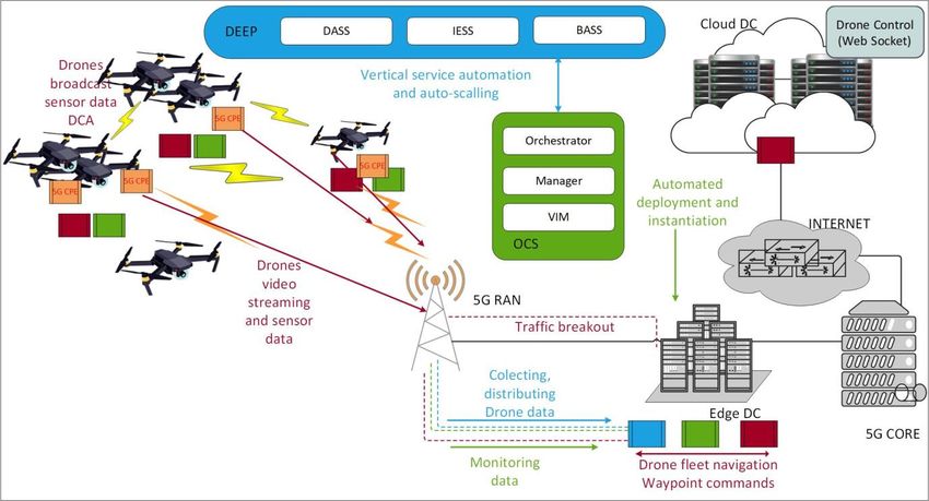
Deliverable D1.1                                                                                        2

Document properties
 Document number                  D1.1
 Document title                   5G-DIVE architecture and detailed analysis of vertical use cases
 Document responsible             III
 Document editor                  Tzu Ya Wang
 Editorial team                   All WP1
 Authors                          Alberto Solano, Luis M. Contreras, Alain Mourad, Carlos
                                  Guimarães, Milan Groshev, Chenguang Lu, Saptarshi Hazra, Chao
                                  Zhang, Angel Segovia, Samer Talat, ChenHao Chiu, YuChing Hsu,
                                  Osamah Ibrahiem, Timothy William and Muhammad Febrian
                                  Ardiansyah
 Target dissemination level       Public
 Status of the document           Final
 Version                          3.0

Production properties
 Reviewers                        Alain Mourad, Carlos Guimarães, Antonio de la Oliva

Document history
 Revision                  Date                      Issued by                 Description
 1.0                       02/03/2020                Tzu Ya Wang               First draft for first
                                                                               review round
 2.0                       16/03/2020                Tzu Ya Wang               Second draft for
                                                                               second review round
 3.0                       30/03/2020                Tzu Ya Wang               Final version

Disclaimer
This document has been produced in the context of the 5GDIVE Project. The research leading to these
results has received funding from the European Community's H2020 Programme under grant
agreement Nº H2020-859881.

All information in this document is provided “as is" and no guarantee or warranty is given that the
information is fit for any particular purpose. The user thereof uses the information at its sole risk and
liability.

For the avoidance of all doubts, the European Commission has no liability in respect of this document,
which is merely representing the authors view.

                                                                                          H2020-859881
Deliverable D1.1                                                                                                                                                         3

Contents
List of Tables ......................................................................................................................................................... 5
List of Figures ....................................................................................................................................................... 6
List of Acronyms .................................................................................................................................................. 7
Executive Summary ............................................................................................................................................. 8
1. Introduction ...................................................................................................................................................... 9
2. COVID-19 Outbreak Risk Assessment ........................................................................................................ 10
3. Specification of Targeted Use Cases ............................................................................................................ 11
   3.1. Industry 4.0 Use Cases ........................................................................................................................... 11
       3.1.1. Industry 4.0 Use Case #1 - Digital Twinning ................................................................................ 12
       3.1.2. Industry 4.0 Use Case #2 - Connected Worker Augmented Zero Defect Manufacturing for
       Decision Support System ......................................................................................................................... 17
       3.1.3. Industry 4.0 Use Case #3 – Massive Machine-Type Communications ..................................... 22
   3.2. Autonomous Drone Scout Use Cases ................................................................................................... 26
       3.2.1. Autonomous Drone Scout Use Case #1 – Drones Fleet Navigation ........................................ 27
       3.2.2. Autonomous Drone Scout Use Case #2 - Intelligent Image Processing for Drones ............... 30
4. Baseline Architecture ..................................................................................................................................... 34
   4.1. Architecture Overview ........................................................................................................................... 34
   4.2. DEEP Platform ......................................................................................................................................... 35
       4.2.1. Data Analytics Support Stratum (DASS) ...................................................................................... 36
       4.2.2. Intelligence Engine Support Stratum (IESS) ................................................................................. 37
       4.2.3. Business Automation Support Stratum (BASS) ........................................................................... 37
   4.3. DEEP Interfaces ....................................................................................................................................... 38
   4.4. Architecture Mapping to Existing Industry Frameworks ................................................................. 40
   4.5. 5G-DIVE applied to the 5G-CORAL Edge Computing Platform ..................................................... 41
       4.5.1. 5G-CORAL Overview...................................................................................................................... 41
       4.5.2. Integration of DEEP with 5G-CORAL .......................................................................................... 43
   4.6. Use Case Mapping to 5G-DIVE Baseline Architecture ...................................................................... 44
       4.6.1. Mapping to I4.0 Use Cases .............................................................................................................. 45
       4.6.2. Mapping to ADS Use Cases ............................................................................................................ 48
5. Conclusions ..................................................................................................................................................... 51
6. References........................................................................................................................................................ 52

                                                                                                                                                  H2020-859881
Deliverable D1.1                                                                                                                                                        4

7. Annexes ........................................................................................................................................................... 54
   7.1. NGMN references for 5G-DIVE use cases ........................................................................................... 54

                                                                                                                                                 H2020-859881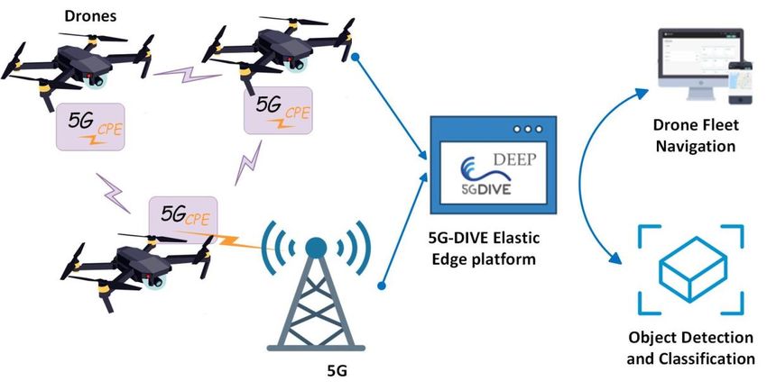
Deliverable D1.1                                                                                                                                             5

List of Tables
Table 3-1: Business requirements I4.0-UC1. ................................................................................................... 16

Table 3-2: Functional requirements I4.0-UC1................................................................................................. 17

Table 3-3: Technical requirements I4.0-UC1................................................................................................... 17

Table 3-4: Business requirements I4.0-UC2. ................................................................................................... 21

Table 3-5: Functional requirements I4.0-UC2................................................................................................. 22

Table 3-6: Technical requirements I4.0-UC2................................................................................................... 22

Table 3-7: Business requirements I4.0-UC3 .................................................................................................... 25

Table 3-8: Functional requirements I4.0-UC3................................................................................................. 25

Table 3-9: Technical requirements I4.0-UC2................................................................................................... 26

Table 3-10: Business requirements ADS-UC1. ............................................................................................... 29

Table 3-11: Functional requirements ADS-UC1. ............................................................................................ 29

Table 3-12: Technical requirements ADS-UC1............................................................................................... 30

Table 4-1: DEEP Interfaces. ............................................................................................................................... 38

Table 4-2: DEEP Functional Block Mapping To Existing Industry Frameworks. ..................................... 40

Table 7-1: NGMN reference for Digital Twin ................................................................................................ 54

Table 7-2: NGMN reference for ZDM ............................................................................................................. 54

                                                                                                                                        H2020-859881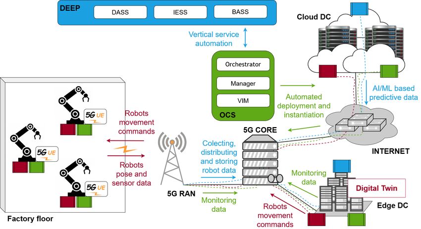
Deliverable D1.1                                                                                                                                           6

List of Figures
Figure 3-1: 5G-DIVE Industry 4.0 Use Cases.................................................................................................. 12

Figure 3-2: Digital Twinning Use Case. .......................................................................................................... 12

Figure 3-3: ZDM Use Case. ............................................................................................................................... 18

Figure 3-4: Massive MTC Use Case ................................................................................................................. 24

Figure 3-5: Autonomous Drone Scout. ............................................................................................................ 27

Figure 4-1: 5G-DIVE Elastic Edge Platform (DEEP). ..................................................................................... 34

Figure 4-2: DEEP Internal Architecture. ......................................................................................................... 36

Figure 4-3: 5G-CORAL Baseline Architecture................................................................................................ 42

Figure 4-4: Integration of 5G-DIVE with 5G-CORAL. .................................................................................. 44

Figure 4-5: Mapping of I4.0-UC1 to 5G-DIVE Solution. ............................................................................... 45

Figure 4-6: Mapping of I4.0-UC2 to 5G-DIVE Solution. ............................................................................... 46

Figure 4-7: Mapping of I4.0-UC3 to 5G-DIVE Solution. ............................................................................... 47

Figure 4-8: Mapping of ADS-UC1 to 5G-DIVE Solution. ............................................................................. 49

Figure 4-9: Mapping of ADS-UC2 to 5G-DIVE Solution. ............................................................................. 50

                                                                                                                                      H2020-859881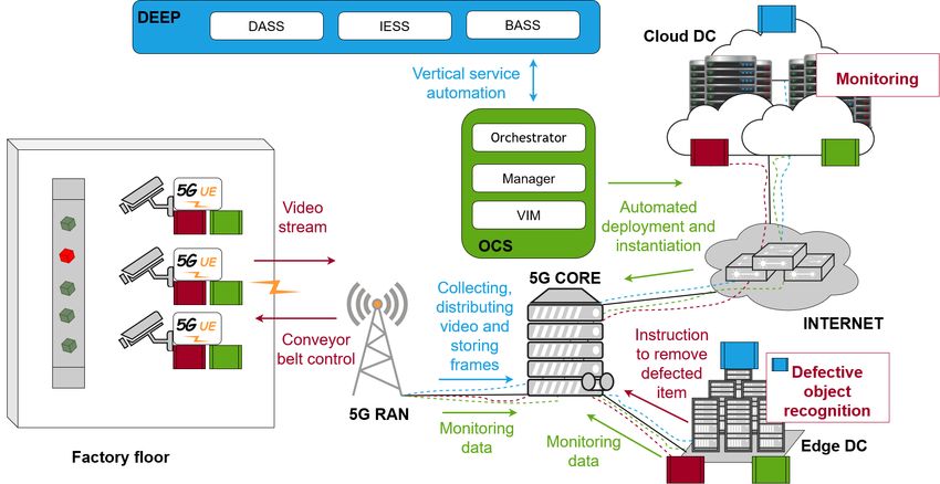
Deliverable D1.1                                                       7

List of Acronyms
 3GPP              3rd Generation Partnership Project
 5GC               5G Core network
 5G NR             5G New Radio
 5G-PPP            5G Private Public Partnership
 ADS               Autonomous Drone Scout
 AI                Artificial Intelligence
 BASS              Business Automation Support Stratum
 CD                Computing Device
 DASS              Data Analytics Support Stratum
 DC                Data Centre
 DEEP              5G-DIVE Elastic Edge Platform
 DL                Downlink
 DNS               Drone Navigation Server
 DSS               Decision Support System
 EFS               Edge and Fog computing System
 eMBB              Enhanced Mobile Broadband
 eNA               enhancements on Network data Analytics
 GPS               Global Positioning System
 HD                High Definition
 I4.0              Industry 4.0
 IaaS              Infrastructure as a Service
 IESS              Intelligence Engine Support Stratum
 IoT               Internet of Things
 KPI               Key Performance Indicator
 NFV               Network Functions Virtualization
 MEC               Multi-access Edge Computing
 ML                Machine Learning
 MTC               Machine Type Communications
 OCS               Orchestration and Control System
 PaaS              Platform as a Service
 PMB               Progressive Map Building
 PID               Person In Distress
 RAT               Radio Access Technology
 RIC               RAN Intelligent Controller
 SAC               Standards Advisory Committee
 WP                Work Package
 UL                Uplink
 URLLC             Ultra Reliability Low Latency
 VIM               Virtualization Infrastructure Manager
 ZDM               Zero Defect Manufacturing

                                                            H2020-859881
Deliverable D1.1                                                                                         8

Executive Summary
This deliverable reports the work carried in 5G-DIVE Work Package (WP) 1“Architecture and detailed
analysis of vertical use cases”, and presents the first results on the targeted use cases, analysis of the
business, functional and technical requirements, as well as the baseline architecture.

The following highlights the key achievements in this deliverable:

    •   A comprehensive description of targeted use cases including three for Industry 4.0, namely i)
        digital twinning, ii) connected worker augmented zero defect manufacturing (ZDM) decision
        support system (DSS), and iii) massive machine-type communications (MTC); and two for
        autonomous drone scout, namely i) drones fleet navigation and ii) intelligent image processing
        for drones.
    •   An initial identification of system requirements for the design of 5G-DIVE solution, the 5G End-
        to-End trial sites for Industry 4.0 and Autonomous Drone Scout (ADS) use cases. These are
        focused on business, functional and technical requirements.
    •   A baseline architecture detailing the internal elements and interfaces of each building block of
        the 5G-DIVE Elastic Edge Platform (DEEP) and describing how to integrate with Edge
        Computing Infrastructure and how the targeted use cases can be implemented following the
        baseline architecture.

All the findings in this deliverable have already been input to the ongoing design by other WPs. Future
work is anticipated to expand and refine these results filling gaps identified and based on feedback
received from the other WPs.

                                                                                           H2020-859881
Deliverable D1.1                                                                                         9

1. Introduction
5G-DIVE project targets end-to-end 5G trials aimed at proving the technical and business values of 5G-
DIVE solution in two vertical pilots, namely Industry 4.0 and Autonomous Drone Scout. The 5G-DIVE
solution is built on two main pillars, namely i) E2E 5G connectivity including 5G New Radio, Cross-
haul transport and 5G Core, and ii) distributed edge and fog computing integrating intelligence closely
to the user. The second pillar extends on the solution developed in the H2020 EU-Taiwan Phase I 5G-
CORAL project, by adding support for automation, analytics and artificial intelligence. The targeted
intelligent 5G-DIVE solution aims at achieving optimized end-to-end performance for each of the
targeted vertical applications.

With the aim to help design targeted 5G-DIVE solution, Work Package 1 (WP1) has invested its efforts
since the project kick-off in October 2019 on two fronts: i) Identifying the targeted use cases and
detailing their technical and non-technical requirements; and ii) Developing a baseline architecture
including functional blocks and reference interfaces for the solution design to follow.

This first deliverable from WP1 is therefore structured in two main sections presented in the sequel, i.e.
Section 3 and Section 4, presented in the sequel after the risk assessment of COVID-19 impacts to WP1
is presented in Section 2:

    •   Section 3 gives a detailed view of the specifics of each use case considered in 5G-DIVE vertical
        pilots including the use case’s objectives, conditions, actors, execution flow, business
        requirements, and technical requirements.
    •   Section 4 is devoted next to the baseline architecture detailing the functional blocks and
        reference points and interfaces that the 5G-DIVE design will follow the outlines the next steps.

The Annex section is added to provide two reference use cases defined in NGMN, which are related to
5G-DIVE use cases.

                                                                                           H2020-859881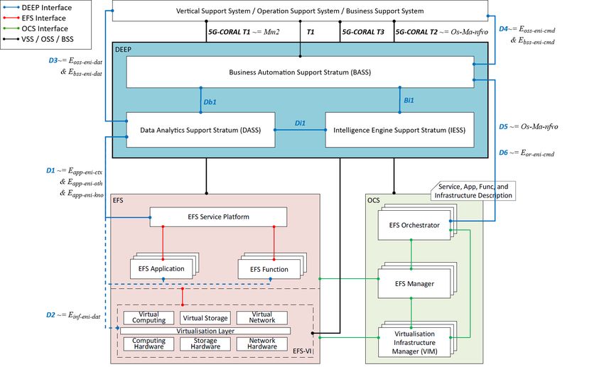
Deliverable D1.1                                                                                       10

2. COVID-19 Outbreak Risk Assessment
Owing to growing impact of COVID-19 outbreak, in this section, we evaluate the possible impact of
following tasks and deliverables execution situation in WP1.

Task 1.2 focuses on the design and validation of the 5G-DIVE platform for the specific vertical use cases
based on the results of the field trials. However, the development work will be slower since some
countries are adopting a work-from-home policy or some companies even closed their office premises.
The remote work will cause a slower interaction among partners and not all of the required actions for
developing the use case can be done remotely.

For the next deliverables, planned for M12, it will be harder to gather the site survey data, because of
the restriction for accessing the buildings, labs and campus. The site survey is assumed to measure
some scenario parameters which will be taken as inputs into the techno-economic analysis, so these
restrictions particularly will slow down the progress of the planned site measurements and
demonstrator implementations.

WP1 is in charge of the overall validation of the vertical industry use cases, gathering the different
inputs from the remaining technical WPs and providing an overall assessment of their outcomes in
terms of business, functional and technical KPIs. General travel restrictions make face-to-face meetings
currently impossible, which might have a further negative impact on the general progress. Thus, the
whole project will be affected and may get delayed by a few months due to the current developments
regarding the Covid-19-pandemic.

                                                                                          H2020-859881
Deliverable D1.1 11
3. Specification of Targeted Use Cases
This section gives a detailed specification of each of the use cases targeted in 5G-DIVE vertical pilots
including the use case’s objectives, conditions, actors, execution flow, business requirements, and
technical requirements, as briefly defined below:
• Use Case Overview: Statements written in natural language together with diagrams of the
services provided by the 5G-DIVE solution and its operational constraints.
• Use Case Objectives: Objectives motivate the purpose and goals the use case aims at fulfilling.
• Use Case Conditions: Conditions that need to be met before the use case may proceed.
• Actors Involved: Person, other systems or machine using the solution to achieve a goal.
• Use Case Flow: A sequence of steps that represents a single use case execution.
• Business Requirements: A business requirement is not something a solution must do. It is
something that the business needs to do or have in order to stay in business. For example, a
business requirement may be a) a process they must complete; b) a piece of data they need to
use for that process; or c) a business rule that governs that process and that data.
• Functional Requirements: The description of the solution’s functions, services and operational
constraints. Defines what should be implemented. Statements of services the solution should
provide, how the solution should react to certain inputs and how the solution should behave in
certain situations. May also state what the solution shall not do.
• Technical Requirements: Constraints on the services or functions offered by the solution such
as timing constraints, constraints on the development process, standards, etc. Technical
requirements are technical issues that must be considered to successfully complete a solution
design. These are aspects such as performance, reliability, and availability that the solution must
meet.
3.1. Industry 4.0 Use Cases
Industry 4.0 delivers the future of the manufacturing industry by combining smart objects and digital
systems capable of autonomously exchanging information, triggering actions and controlling each
other independently. The goal is to create flexible and resource efficient production systems in
manufacturing and to integrate industry, business, and internal processes through computer-based
systems [1].
Three Industry 4.0 use cases are targeted in 5G-DIVE, namely i) digital twinning application and ii)
connected worker augmented zero defect manufacturing decision support system, and iii) massive
MTC scaled for monitoring and predicative maintenance. An initial schema of the 5G-DIVE solution
supporting these two use cases is depicted in Figure 3-1. More details will be described in the following
subsections for three use cases, respectively.
H2020-859881Deliverable D1.1 12
FIGURE 3-1: 5G-DIVE INDUSTRY 4.0 USE CASES.
3.1.1. Industry 4.0 Use Case #1 - Digital Twinning
3.1.1.1. Overview
Digital Twins are digital replicas of physical assets (see Figure 3-2), processes, and systems that also
interact with the real system, where the digital replica reproduces changes as they occur in the actual
physical system. The concept has been around for some time now, but it has found a limited application
until recently, due to storage costs, processing power, and bandwidth performances.
FIGURE 3-2: DIGITAL TWINNING USE CASE.
This use case will demonstrate End-to-End 5G performance for interconnecting a real robot to its digital
twin, which will share the computing resources and the software with the real robot and will virtually
H2020-859881Deliverable D1.1 13
replicate the same function. The robot will be controlled in real time, remotely by a virtual controller
located either in a closer vicinity to remote worker or in the cloud or in a powerful dedicated resource.
Also, if we want to target very low latencies, we may need to deploy things in the Edge. The robot will
receive instructions about its position in a stepwise manner by the controller, while sensor data will be
sent back to provide a real-time feedback to the remote controller. Both control instructions and
information from sensors will be used to update the virtual model in real-time. Said model can be used
to highlight critical conditions inferred by sensors data and to provide alarms and preventive
maintenance information to humans.
In case that critical or dangerous situations are detected, the remote control could stop in real time the
operations for safety reasons. Safety requires a very reliable and fast track for transmission of data and,
among wireless technologies, only 5G can satisfy these tight requirements.
In industrial applications, the overall End-to-End latency budget (time delay between data being
generated at a sensor and the data being correctly received by the actuator) is spent for the processing
time of the data received by sensors; the remaining part of the latency budget limits communication
time to a few milliseconds.
5G connectivity will guarantee the reliability and the low latency remote control and, at the same time,
fully support the safety functions. In addition, the fixed connectivity with ultra-short delay will be
provided between the Fog/Edge and Cloud, distributing the computational needs across the different
tiers enabling a reduced reaction time of the digital twin.
Output
The digital twin use case will provide a virtual replica of a robot or of a part of a production line. The
5G network coverage will be deployed to enable real-time visibility and remote insights into robot
status and performance without having to directly operate on the physical machine.
Benefit
Using a digital twin will facilitate, with respect to the real operating machines, assessing the concepts
of remote control, monitoring for preventive maintenance, and safety that can be applied in a factory
in large scale and with high density of devices.
3.1.1.2. Objectives
The objectives of this use case (I4.0-UC1) are listed below:
• To demonstrate 5G performance for interconnecting a real robot to its digital twin. For such a
purpose, the digital twins, sharing the computing resources and the software, will virtually
replicate the same function.
• To provide advanced network connectivity with low latency inside the Fog/Edge and Cloud,
distributing the computational needs across the different tiers in order to reduce the reaction
time of the digital twin.
H2020-859881Deliverable D1.1 14
• To monitor the operation of the physical robot in order to detect critical conditions and take
adaptive measures to mitigate them.
• To mitigate latency variations in the remote control in order to correctly operate the physical
device.
• To demonstrate automation capabilities for driving up the business value and reducing
operational costs.
3.1.1.3. Conditions
The conditions for I4.0-UC1 are listed below:
• 5G radio must be available at the plant and must be able to collect data from many PLCs
guaranteeing no perceived delay in the virtual representation.
• High bandwidth and low latency communications must be provided for the on-time delivery
of the information of the sensors to the virtual twin and for the interaction with the digital
model.
• Computing resources must be located both on premises and externally at the Fog/Edge for the
correct operation of the use case.
3.1.1.4. Actors Involved
The actors involved in the I4.0-UC1 use case are identified below:
• Plant Manager: Person who uses monitoring application for updates about the status of each
machinery in the production line, in case of problems, he/she may arrange maintenance
activities in order to prevent stops. Plant Manager is the person who mainly uses this
application to be updated about the current, past and future status of plant production lines
and carry out actions to keep production rate optimised.
• Digital Worker: The operator who checks if his/her production is in line with the programmed
one and participate in warding off bottlenecks or failure due to plant manager decisions.
• Expert: The expert is the person in charge of performing the calibration and configuration of the
physical device.
3.1.1.5. Execution Flow
In the following, we present different execution flows using the abovementioned actors.
Flow 1 – Configure and calibrate Digitals Twins
1. The Digital worker will request the remote connection between digital replica and physical
assets. The worker will easily plug the systems and configure the Digitals Twins.
2. The digital worker will choose the SLAs for the service.
3. The expert configures the machine and charges the measuring program prepared and simulated
offline.
H2020-859881Deliverable D1.1 15
4. The physical assets perform an end-to-end 5G connectivity in accordance with the SLAs and
will respond with a success message or connection failure message.
5. If it fails, a new connection must be requested.
6. If successful, the digital worker will request a test for adjustments. To perform the test, the
digital worker will request predefined actions on the digital replica to be performed by the
physical robot.
7. These movements will be captured by the sensors and verified by the digital worker. The two
cameras show the movement to the worker as it happens.
8. If it fails, the faults found in this calibration process will be reported for adjustments. The IT
department intervention may be required if it fails again.
9. If successful, the sensors will send a message to the Digital Controller and the digital twins will
be ready to work. The Digital worker now can use the Digital Twin.
Flow 2 – Perform Action Replica with Twins Robots
1. The digital worker will request actions to be performed in real time on the twin robot through
the controller. Real Robot will be controlled remotely by a virtual controller located on a
Fog/Edge device or a virtual machine.
2. The robot will receive instructions about its position in a stepwise manner by the controller and
will perform the exact requested actions in real time.
3. The robot may require changes in topology to perform the designated action and keep the SLAs.
For this, an orchestrator monitors the behaviour performance that will predictively perform
elasticity on slices, if necessary.
4. While performing the actions, sensors capture and report data about these actions, which are
sent to the controller and datacentre. The actions generate sensitive information that will be
processed locally and enhanced with context data to take action in real time, if necessary.
5. This data is processed by an AI tool to enhance the orchestration and control functions such as
federation, orchestration, and enforcement of SLAs.
Flow 3 - Control Loop and Dashboard
1. The monitoring / telemetry app constantly monitors the real robot deployed on the production
field and provides their status to the plant manager/digital worker through a dashboard.
Sensors capture and report data about the robot which are sent to the controller and datacenter.
2. The actions generate sensitive information that will be processed locally and enhanced with
context data to act in real time, if necessary. Control instructions and information from sensors
will be used to update the virtual model in real-time. Meanwhile, sensor data will be sent back
to provide real-time feedback to the remote controller.
3. The Controller will analyse the received data and turn it into information. Control instructions
and information from sensors will update the virtual model in real-time. The tool collects data
from the field as cycle time values and in case of deviations it performs calculations to predict
if there will be bottlenecks or line stops. The Controller, through an AI tool, will evaluate and
H2020-859881Deliverable D1.1 16
suggest changes to be made. This data is processed by an AI tool to enhance the orchestration
and control functions such as federation, orchestration, and enforcement of SLAs.
4. The virtual model will be used to highlight critical conditions inferred by sensors data and to
provide alarms and preventive maintenance information to humans. The plant manager/digital
worker uses the dashboard to monitor actual production and statistical data about historical
data. Plant manager has access to a suggestion tool which can show some actions to avoid the
problems detected. The digital workers and plant managers may request the execution of the
suggested changes or define other actions from the obtained data.
5. The plant manager can monitor the effects of his decisions, they can monitor data coming from
the field after the re-arrangement.
Flow 4 - Respond to Critical Behavior Detected
1. The sensitive information will be processed locally and enhanced with context data to act in real
time, if necessary.
2. The Controller, through an AI tool, will evaluate and suggest changes to be made. This data is
processed by an AI tool to enhance the orchestration and control functions such as federation,
orchestration, and enforcement of SLAs.
3. In case of unexpected problems, the plant manager can change maintenance schedule in order
to prevent machinery faults. The IT department must keep updated and maintained all the
virtual machine in order to guarantee high availability and reliability.
4. In case that critical or dangerous situations are detected, the remote control will stop in real time
the operations for safety reasons. In industrial applications, the overall end-to-end latency
budget (time delay between data being generated at a sensor and the data being correctly
received by the actuator) is spent for the processing time of the data received by sensors, the
remaining part of the latency budget limits communication to few milliseconds.
5. In case of problems in a production plant where there is no maintenance operator, it is possible
to call the right technician to drive step by step the maintenance task.
6. A message should be sent to digital worker and plant manager advising the actions taken and
the reasons.
3.1.1.6. Business Requirements
Table 3-1 presents the business requirements for I4.0-UC1. These are performance improvements as
desired by the business operator of the use case.
TABLE 3-1: BUSINESS REQUIREMENTS I4.0-UC1.
BR - ID Description
Reduce technicians’ travels by 30% by allowing them to remotely control the
BR-I4.0-UC1-01
physical robot
BR-I4.0-UC1-02 Reduce failure rate at least of 20% with objective 90%
BR-I4.0-UC1-03 Improve service response time by 30%
H2020-859881Deliverable D1.1 17
3.1.1.7. Functional Requirements
Table 3-2 summarizes the functional requirements needed to meet the aforementioned business
requirements.
TABLE 3-2: FUNCTIONAL REQUIREMENTS I4.0-UC1.
FR - ID Description
Leverage AI to automate procedures, enable predictions and provide
FR-I4.0-UC1-01
recommended actions accordingly
FR-I4.0-UC1-02 Provide E2E 5G connectivity inside the plant and to the outside public network
FR-I4.0-UC1-03 Guarantee information updates with unnoticeable delay
FR-I4.0-UC1-04 Support remote control protocols using wireless as an alternative to cable today
3.1.1.8. Technical Requirements
Table 3-3 gives the technical requirements in the form of target performance values to be met for the
use case to operate seamlessly.
TABLE 3-3: TECHNICAL REQUIREMENTS I4.0-UC1.
TR - ID Description Value
TR-I4.0-UC1-01 Reference Availability [Table 7-1] 99.9999%
TR-I4.0-UC1-02 Reference Reliability [Table 7-1] 99.999%
TR-I4.0-UC1-03 Reference E2E Latency [Table 7-1] 20ms
TR-I4.0-UC1-04 Remote control bandwidth per instance (DL) 100Kbps
TR-I4.0-UC1-05 Video bandwidth per instance (UL) 5Mbps
TR-I4.0-UC1-06 Reference Connection density [Table 7-1]Deliverable D1.1 18
FIGURE 3-3: ZDM USE CASE.
Thanks to those devices and the intelligence deployed on them it is possible to detect characteristic
patterns that allow the recognition of defects in the production line. In this sense, if a piece is detected
as good, no action will be taken. However, when a piece is detected as defective, new mechanisms are
triggered in order to take the piece out of the production line. This is achieved by using AI-based
pattern/object recognition of the video feed. It can be said that the sooner a piece is detected as defective
there is less scrap associated. The analysis of the video stream in the Fog/Edge will make cameras with
pattern recognition simpler and cheaper. Due to the number of cameras and the bandwidth required
by the videos, it becomes very difficult to centrally process the information gathered, both in terms of
data storage and fast data analysis, and consequently to extract and capitalize on the corresponding
knowledge. Due to this reason, the information processing in Edge datacentres becomes mandatory for
the operation of this use case.
5G connectivity arises as the solution able to provide the reliability and the low latency operation
required by the previously described production line. In addition, a fast analysis of the video stream in
the Edge and not in the device will require high bandwidth, low latency and high reliability enabled
only by 5G, which will impact the number of piece analysis. The faster pieces are analysed, the more
pieces can be produced in the same time.
Output
This use case will explore the capabilities of 5G connectivity extended with Fog/Edge to address the
performance needs including real-time processing and visualization of geometric features for
manufactured parts.
Benefit
The use of ZDM techniques may potentially reduce scrap by 100%, and predict form and/or welding
errors, which will potentially increase the productivity of factories and quality of the goods.
3.1.2.2. Objectives
The objectives for this I4.0-UC2 use case are outlined below:
H2020-859881Deliverable D1.1 19
• To demonstrate 5G performance for delivering high-bandwidth traffic coming from the camera
towards a monitoring application able to identify defective pieces.
• To demonstrate 5G and Edge capability to deliver low latency required to reduce reaction
between the identification of the defective piece and its removal of the production line.
• To highlight critical conditions inferred by the camera data and provide alarms and preventive
maintenance information.
• To provide plant managers with actual information about the status of the production lines,
predicting future failures or bottlenecks, giving the opportunity to move up actions and prevent
problems thanks to the monitoring process.
3.1.2.3. Conditions
The conditions for this I4.0-UC2 use case are listed below:
• 5G must be available at the plant facilities and must be able to interconnect all the different
hardware in the production line (e.g., cameras, conveyor belt, removal tool, etc).
• High bandwidth and low latency communications must be provided for the on-time delivery
of the information of the video camera to the monitoring application and, afterwards, its
interaction with the removal tool.
• The video camera equipment shall be present in the conveyor belt installation in order to feed
the monitoring platform with real time data.
3.1.2.4. Actors Involved
The actors involved in the execution of this I4.0-UC2 use case are listed hereafter:
• Digital worker: the operator who checks if his/her production is in line with the programmed
one and participates in warding off bottlenecks or failure due to plant manager decisions.
• Plant Manager: the person who uses an application for updates about the current, past and
future status of plant production lines and carries out actions to keep production rate optimised.
• Maintenance operator: the operator who adjusts and/or operates the equipment at the premises
when there are malfunctioning situations with the aim of retrieving the normal flow of
operation as soon as possible.
3.1.2.5. Execution Flows
Flow 1 – Configure and calibrate Video Cameras
1. The Digital worker will request the video camera connection to the command centre. The
worker will easily plug the systems and configure the cameras.
2. The digital worker will choose the SLAs for the service.
3. The physical assets perform an End-to-End 5G connectivity in accordance with the SLAs and
will respond with a success message or connection failure message.
4. If it fails, a new connection must be requested.
H2020-859881Deliverable D1.1 20
Flow 2 - Control Loop
1. The monitoring application constantly monitors the performance capabilities for supporting
real time analysis of HD/4K video of goods being produced on a line, in order to detect possible
defects.
2. The cameras collect different pieces of information about production that will be processed
locally and enhanced with context data to act in real time, if necessary. But it also collects
information about the operation of the application to monitor and control the performance of
devices. Control instructions and information from cameras will be used to update the control
model in real-time.
3. The AI algorithm uses this information to detect characteristic patterns for defects in the
production, this is deployed in the Fog devices to a fast data analysis. Problems detected on the
production line are reported and / or addressed in real time by an AI tool.
Problems about device performance will be addressed as follows:
1. The tool collects data from the field as cycle time values and in case of deviations performs
calculations to predict if there will be bottlenecks or line stops.
2. The Controller, through an AI tool, will evaluate and suggest changes to be made. This data is
processed by an AI tool to enhance the orchestration and control functions such as federation,
orchestration, and enforcement of SLAs.
Flow 3 - Respond to Critical Behavior Detected
1. During monitoring, some behaviors can be observed. These will be processed locally and
considered critical.
2. The sensitive information will be processed locally and enhanced with context data to act in real
time, if necessary.
3. The Controller, through an AI, will evaluate and suggest changes to be made. This data is
processed by an AI tool to enhance the orchestration and control functions such as federation,
orchestration, and enforcement of SLAs.
4. In case of unexpected problems, the plant manager may change maintenance schedule in order
to prevent machinery faults. The IT department keeps updated and maintained all the virtual
machine in order to guarantee high availability and reliability.
5. In case that critical or dangerous situations are detected, the remote control will stop in real time
the operations for safety reasons. In industrial applications, the overall end-to-end latency
budget is spent for the processing time of the data received by sensors, the remaining part of
the latency budget limits communication to few milliseconds.
6. In case of problems in a production plant where there is no maintenance operator it is possible
to call the right technician to drive step by step the maintenance task.
7. A message should be sent to digital worker and plant manager advising the action taken and
the reason.
Flow 4 - Augmented Zero Defect Manufacturing (ZDM) Decision Support System (DSS)
H2020-859881Deliverable D1.1 21
1. The monitoring application has an algorithm able to detect characteristic patterns for defects in
the production. Data is collected in real time for this analysis. The sensitive information will be
processed locally and enhanced with context data to act in real time, if necessary.
2. The algorithm uses this information to detect characteristic patterns for defects in the
production, this is deployed in the Fog devices to a fast data analysis. Problems detected on the
production line are reported and / or addressed in real time by an AI tool. This algorithm is
responsible for centralizing the information received by various cameras. This requires 5G high
bandwidth for the interaction with the platform for reinforced learning and 5G low latency for
processing of results in the Fog devices.
3. Defective pieces are automatically removed from the production line.
4. When a problem is detected, some video cameras start broadcasting real-time video images
(supporting real time analysis of HD/4K) start to be transmitted to control model.
5. The control model will be used to highlight critical conditions inferred by sensors data and to
provide alarms and preventive maintenance information to humans. The plant manager /
digital worker uses the dashboard to monitor actual production and statistical data about
historical data. Plant manager has access to a suggestion tool which can show some actions to
avoid the problems detected. The digital workers and plant managers may request the
execution of the suggested changes or define other actions from the obtained data. The plant
manager can monitor the effects of his decisions, they can monitor data coming from the field
after the re-arrangement.
6. In case of unexpected problems, the plant manager may change maintenance schedule in order
to prevent machinery faults. The IT department keeps updated and maintained all the virtual
machine in order to guarantee high availability and reliability.
7. In case that critical or dangerous situations are detected, the remote control will stop in real time
the operations for safety reasons. In industrial applications, the overall end-to-end latency
budget is spent for the processing time of the data received by sensors, the remaining part of
the latency budget limits communication to few milliseconds.
8. A message should be sent to digital worker and plant manager advising the action taken and
the reason.
3.1.2.6. Business Requirements
Table 3-4 presents the business requirements for I4.0-UC2. These are performance improvements as
desired by the business operator of the use case.
TABLE 3-4: BUSINESS REQUIREMENTS I4.0-UC2.
BR - ID Description
BR-I4.0-UC2-01 Reduce cost of production by 10%
Increase the production throughput by 15% by improving the detection
BR-I4.0-UC2-02
rate of defective pieces in production
Reduce customer visits by 40% by reducing the number of trips of the
BR-I4.0-UC2-03
customer to the factory for quality assurance of the produced goods
H2020-859881Deliverable D1.1 22
BR-I4.0-UC2-04 Reduce scrap of at least 10% with an objective of achieving 0 scrap
Detect up to 30% of form and/or welding errors so anticipative measures
BR-I4.0-UC2-05
may be deployed to mitigate these errors
3.1.2.7. Functional Requirements
Table 3-5 summarizes the functional requirements needed to meet the aforementioned business
requirements.
TABLE 3-5: FUNCTIONAL REQUIREMENTS I4.0-UC2.
FR - ID Description
Leverage AI to automate procedures, enable prediction and provide
FR-I4.0-UC2-01
recommended actions accordingly
FR-I4.0-UC2-02 BASS will be able to scale up and down the system in order to guarantee SLAs
Provide E2E 5G connectivity inside the plant facilities and outside to the public
FR-I4.0-UC2-03
network
Guarantee the delivery of information from the cameras to the monitoring
FR-I4.0-UC2-04
application with minimal delay
FR-I4.0-UC2-05 Support remote control protocols using wireless as an alternative to cable today
3.1.2.8. Technical Requirements
Table 3-6 gives the technical requirements in the form of target performance values to be met for the
use case to operate seamlessly.
TABLE 3-6: TECHNICAL REQUIREMENTS I4.0-UC2.
TR - ID Description Value
TR-I4.0-UC2-01 Availability [Table 7-2] 99.9999%
TR-I4.0-UC2-02 Expected Reliability [Table 7-2] 99.9999%
TR-I4.0-UC2-03 Reference E2E Latency [Table 7-2] 10ms
TR-I4.0-UC2-04 Remote control bandwidth per instance (DL) 100Kbps
TR-I4.0-UC2-05 Video bandwidth per instance (UL) 5Mbps (per camera)
TR-I4.0-UC2-06 Reference Connection density [Table 7-2]Deliverable D1.1 23
3.1.3.1. Overview
Massive machine-type communications (MTC) enables connectivity for a massive number of small low-
power low-cost sensor nodes. These aggregations of data from these sensor nodes provide insights into
the industrial workflows and plant operations enabling closed-loop control. In the context of Industry
4.0, one example is process and asset monitoring [2] in the context of industrial production, which
facilitates predicative maintenance with the monitored data available. Process monitoring connect
critical industrial machinery with sensor nodes and actuators for providing insights into the current
industrial workflows. These insights and analytics will be used for predictive maintenance using closed
loop control. The current working environment inside a plant will be monitored through
environmental monitoring which enables maintaining a productive work environment for the plant
workers and preventing dangerous situations like fire hazards.
Traditionally in massive MTC network design, IoT stacks are implemented in HW ASIC chipsets
in IoT gateways or base stations, which are deployed in the field. The amount
of baseband resources (in HW) required equals to the number of gateways deployed. The total
baseband resources don’t scale with the actual traffic, which follows an over-dimensioning
principle. When traffic is low, the resources are wasted. Further, the baseband capability and
capacity are limited by the chipset capability, which is hard to upgrade once it is deployed. When more
and more IoT devices are deployed, those gateways deployed need to be HW upgraded and replaced
by new gateways with newer generation of HW with higher processing power to support more capacity
and new features. Such an approach is not scalable and future proof to support ever-increasing number
of IoT devices.
In this use case, the scalability and future proof are addressed by implement Cloud RAN for IoT.
Instead of a fully functional gateway, a split architecture following Cloud RAN is adopted. The full
gateway function is split into two part: radio heads and virtualized SW gateway at the Edge or Cloud,
as illustrated in Figure 3-4. The radio heads perform mainly the radio functions and minor digital
functions, while most baseband functions are implemented in the virtualized SW gateway. This use
case will provide connectivity to dense deployments of IoT nodes across multiple IoT radio access
technologies. As radio heads become simpler with minimum baseband functions, it can be designed to
be more future proof, e.g. supporting more IoT carriers and bands. In this way, the lifetime of radio
heads would be much longer than the traditional gateway. The virtualize SW gateway are deployed in
a Cloud environment which could help achieve web-scale scalability and availability with orchestration
features, like load balancing and auto-scaling. This would also provide resource pooling gain achieving
better resource utilization scaling with IoT traffic load, along with flexibility. Automation will be also
enabled, e.g. for automated life cycle management, to reduce the operational costs.
H2020-859881Deliverable D1.1 24
FIGURE 3-4: MASSIVE MTC USE CASE
Furthermore, the incorporation of softwarized approaches and integration of multiple radio access
technologies allows us to enable AI/ML based intelligent services which address coordination across
different RATs and security challenges for the massive number of IoT devices.
Service-based data pipelines collect, store and organize the data gathered from the sensor nodes
through the connectivity services. The IoT application accesses the data pipelines through well-defined
procedures for visualizations and generating insights into the current industrial workflows and plant
operations through data analytics. The data analytics can trigger actuation routines on certain pre-
configured conditions through the connectivity services provided by the IoT gateway for closed-loop
control e.g. actuation routines for predictive maintenance in the infrastructure monitoring case and
maintaining productive working environment in the plant.
Output
The massive MTC will provide connectivity for dense heterogeneous (multiple RATs) deployments of
IoT sensor nodes using intelligent and scalable connectivity services located at the edge of the network.
The use case will also provide data pipelines supporting service-based architecture for the IoT sensor
data including data visualization and data retrieval procedures.
Benefit
Our massive MTC use case focus on process and asset monitoring, e.g. infrastructure monitoring and
environmental monitoring
Infrastructure monitoring: we connect the already available machinery with sensor nodes and collect
data. This data can be used for gaining insights into the runtime operations of the industrial workflows
and how they align with the business goals. Also, the health of the machinery can be tracked, which
will allow us to do predictive maintenance if needed reducing downtime of these machineries.
Environmental monitoring: using environmental monitoring (e.g. temperature, humidity, noise etc.),
we ensure the safety and security of the plant. The data from these can be useful in increasing the
productivity of the workers with proper closed-loop control. These data can help in preventing
dangerous situations in the plant like fire hazards saving critical industrial machinery, human cost and
downtime.
H2020-859881Deliverable D1.1 25
3.1.3.2. Objectives
The objectives for this I4.0-UC3 use case are outlined below:
• To demonstrate connectivity performance of virtualized IoT gateways for supporting dense
deployments of IoT sensors.
• To demonstrate the orchestration and automation features of the IoT connectivity services.
• To demonstrate the intelligence features of the virtualized IoT gateways
• To demonstrate a service-based data pipeline architecture for providing sensor data about the
status of plant and workflows.
3.1.3.3. Conditions
The conditions for this I4.0-UC3 use case are listed below:
• Fixed or wireless network infrastructure are available to provide network connectivity between
radio heads and virtualized IoT gateways at the Edge or in Cloud.
• Network bandwidth and latency fulfils the requirement of specific RATs used.
• Adequate computing, network and storage resources are available in the Edge and Cloud
infrastructure for hosting virtualized IoT gateways and applications.
• Large number of wireless sensors and/or actuators with different RATs are deployed at the
factory premises.
• Radio heads are deployed to provide coverage of the factory premises where wireless sensors
and/or actuators are deployed.
3.1.3.4. Business requirements
Table 3-7 presents the business requirements for I4.0-UC3. These are performance improvements as
desired by the business operator of the use case.
TABLE 3-7: BUSINESS REQUIREMENTS I4.0-UC3
BR - ID Description
BR-I4.0-UC3-01 Reduce IoT network deployment cost by 25%
BR-I4.0-UC3-02 Reduce IoT network operational cost by 20%
BR-I4.0-UC3-03 Reduce mean time between failures by 50%
3.1.3.5. Functional requirements
Table 3-8 summarizes the functional requirements needed to meet the aforementioned business
requirements.
TABLE 3-8: FUNCTIONAL REQUIREMENTS I4.0-UC3
FR – ID Description
FR-I4.0-UC3-01 Orchestration with automated life cycle management
FR-I4.0-UC3-02 Orchestration with load balancing and auto-scaling
FR-I4.0-UC3-03 Virtualized IoT RAN supporting multiple RATs
H2020-859881Deliverable D1.1 26
FR-I4.0-UC3-04 Orchestration optimization with ML/AI
3.1.3.6. Technical requirements
TABLE 3-9 gives the technical requirements in the form of target performance values to be met for the
use case to operate seamlessly.
TABLE 3-9: TECHNICAL REQUIREMENTS I4.0-UC2.
TR - ID Description Value
Application layer end-to-endDeliverable D1.1 27
FIGURE 3-5: AUTONOMOUS DRONE SCOUT.
The collected data is then transmitted to the edge of the network for cognitive processing and decision
making. Furthermore, the fleet control will be managed via drone fleet navigation software on the edge.
Together, the communication and the computing capabilities of the platform facilitate the necessary
means for low-cost and efficient rescue efforts. Besides, the facilitated drone navigation leverages
drone-to-drone communication for drone’s collision avoidance.
This scenario will be used to evaluate two use cases, namely i) Drones Fleet Navigation, and ii)
Intelligent Image Processing for Drones. These are detailed in the sequel.
3.2.1. Autonomous Drone Scout Use Case #1 – Drones Fleet Navigation
3.2.1.1. Overview
Traditionally, drones are navigated through a set of GPS coordinates which are pre-loaded into the
drone navigation software. This scheme, known as Way-point navigation, does not allow autonomous
modification to the flight path.
To this end, Autonomous Drone Scout Use Case 1 (ADS-UC1) aims at enhancing the current navigation
system to enable local and remote data processing as well as dynamic change to flight trajectory for the
drone fleet. To accomplish this, a coordination mechanism among drones in the drone fleet is
required. Each drone in the fleet captures and transmits image and GPS data to the edge datacenter
through 5G. Next, edge applications process the received data in real-time to automate the fleet
navigation.
With this use case, coordination mechanisms (centralized in regular flight mode or distributed if the
collision avoidance system detects any collision possibility) among drones in the drone fleet will be
required. Besides, the drone-to-drone direct link and Drone fleet relay will be developed and will be
H2020-859881Deliverable D1.1 28
used to maintain the synchronization among various drones to cover more space and avoid any
collision.
Output
ADS-UC1 will improve the state-of-the-art drone product portfolio through providing enhanced drone
fleet coordination and piloting. Specifically, the coordination and the navigation of the drone fleet will
be entirely autonomous through two main key technologies, 5G network and edge computing.
Benefit
Drone fleet navigation enhanced capabilities will enable new drone-based services such as drone
delivery, drone inspection and monitoring, drone scouting, drone aerial imaging and large-scale
precision agriculture.
3.2.1.2. Objectives
The objectives of the ADS-UC1 use case are summarized below:
• To demonstrate the performance of 5G system integrating intelligent edge in connecting and
navigating a fleet of drones seamlessly. The collected data from drones is transmitted over 5G
for processing at the edge.
• To provide low latency inter-server connectivity at the edge (e.g. using OPTUNS technology)
for near real-time data processing and drones fleet navigation.
• To monitor drones flight status in order to detect and avoid collisions during rescue missions
through intelligent drone-to-drone collaboration.
• To demonstrate the benefits of automation and scalability for drone fleet navigation.
3.2.1.3. Conditions
The conditions for ADS-UC1 use case are listed below:
• High bandwidth is required for on-time delivery of the information (sensing, imaging, and
control) among drones and between drones and the edge.
• The weather condition shall satisfy the minimum requirement for safe drone piloting. This
includes wind speed for drone handling and clear visibility.
• The edge computing resources shall always be available to ensure seamless operation and
scalability.
3.2.1.4. Actors Involved
The actors involved in the execution of ADS-UC1 are listed below:
• Mission Manager: ground drone operator who continuously monitors the flight state of each
deployed drone via a dashboard and remotely intervene with drone operations only when
manual control is required.
• Rescue Team: personnel that may interact with the disaster site for emergency relief.
H2020-859881You can also read