Impact of Inverter-Based Resources on System Protection
←
→
Page content transcription
If your browser does not render page correctly, please read the page content below
Impact of Inverter-Based
Resources on System
Protection
Aboutaleb Haddadi, Ph.D.
Sr. Engineer Scientist
Grid Ops. & Planning R&D Group
Electric Power Research Institute,
U.S.A.
ahaddadi@epri.com

WECC Short-Circuit Modeling Work Group Meeting
Oct 2021

www.epri.com    © 2021 Electric Power Research Institute, Inc. All rights reserved.
Motivation, Challenges & Needs
                            • Continuously increasing penetration level of inverter based
                            resources (IBR), predominantly renewables (Type III, Type IV
                            WTGs & PVs)

                                                                          Challenge
                            • Complex fault response
                            • Differs significantly from synchronous short-circuit current
                            contribution

                                                       Impact on System Protection
                            • Accurate short-circuit models for protection/planning
                              studies
                            • Performance of legacy protection schemes (distance
                              protection etc.)

2            www.epri.com       © 2021 Electric Power Research Institute, Inc. All rights reserved.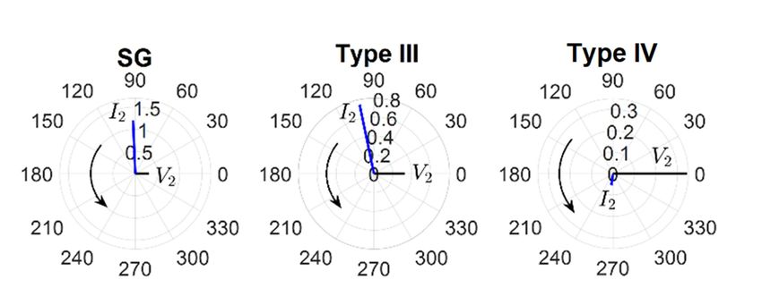
Agenda

1) IBR Technologies
2) IBR Fault Response Characteristics
3) Impact of IBR on Transmission System Protection

3            www.epri.com     © 2021 Electric Power Research Institute, Inc. All rights reserved.
IBR Technologies

4   www.epri.com     © 2021 Electric Power Research Institute, Inc. All rights reserved.
Type IV Wind Turbine Generator (WTG)
                                     Machine-side
                                      Converter                                              Chopper

•    Electrical generator:
     • Induction generator
     • Conventional synchronous generator
     • Permanent magnet synchronous generator (PMSG)
•    Full sized back to back AC/DC & DC/AC converter
     • Machine Side Converter (MSC)
     • Grid Side Converter (GSC)
•    Resistive chopper for DC bus overvoltage protection
•    Generator decoupled from the grid
5              www.epri.com         © 2021 Electric Power Research Institute, Inc. All rights reserved.
Type IV WTG – Typical Fault Response

6           www.epri.com   © 2021 Electric Power Research Institute, Inc. All rights reserved.
Type III WTG

                                             Rotor-side Converter

    • Electrical generator: Doubly Fed Induction Generator (DFIG)
    • Partially rated (~30%) back to back AC/DC & DC/AC converter
         • Rotor Side Converter (RSC)
         • Grid Side Converter (GSC)
    • Resistive chopper for DC bus overvoltage protection
    • Generator not decoupled from the grid
    • Crowbar may activate to short rotor windings and protect the converter. WTG behaves like a squirrel cage
     induction machine
7                   www.epri.com               © 2021 Electric Power Research Institute, Inc. All rights reserved.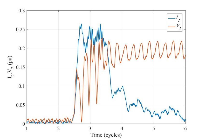
Type III WTG – Typical Fault Response

8           www.epri.com   © 2021 Electric Power Research Institute, Inc. All rights reserved.
Solar Photovoltaic

      •Front-end control is similar to a Type IV WTG.
      •System-level short circuit behavior is similar to Type IV WTG.

9             www.epri.com        © 2021 Electric Power Research Institute, Inc. All rights reserved.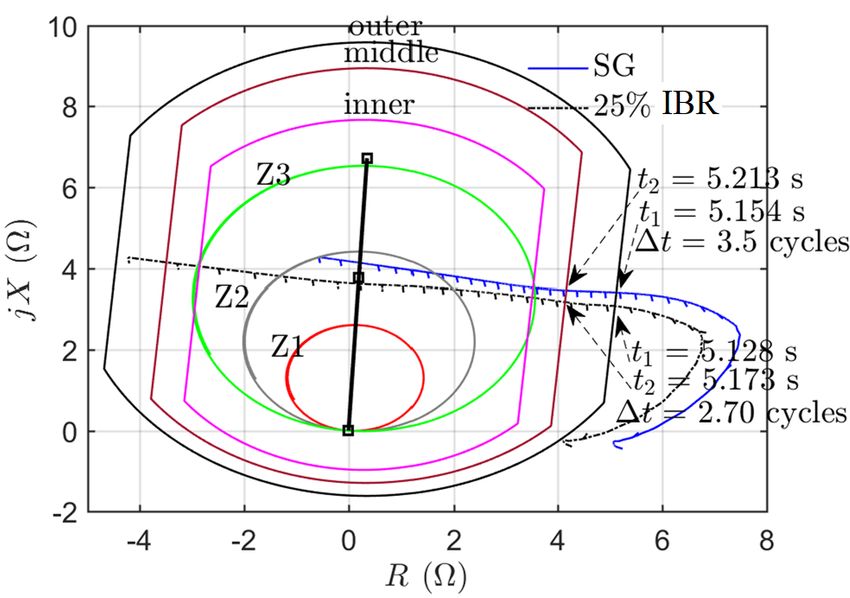
IBR Short-Circuit Modeling

10   www.epri.com         © 2021 Electric Power Research Institute, Inc. All rights reserved.
IBR Short-Circuit Modeling

              Synchronous generator classical short circuit model (voltage source behind
              an impedance) is not applicable

        • EPRI Project 173.09 “Impact of Renewables on System Protection”
        • IEEE PSRC WG C24 “Modification of Commercial Fault Calculation Programs for Wind
          Turbine Generators”

11              www.epri.com            © 2021 Electric Power Research Institute, Inc. All rights reserved.
IBR Short-Circuit Model
Voltage-dependent
current source
representation of IBR
implementations
Equation-based model VCCS model
• Both implementations are nonlinear.
• Solution requires iteration with
network solver.
12 www.epri.com © 2021 Electric Power Research Institute, Inc. All rights reserved.Inverter Based Resource Fault Response
Characteristics
13 www.epri.com © 2021 Electric Power Research Institute, Inc. All rights reserved.Inverter Based Resources Fault Response Characteristics
Synchronous Generator (SG)
•Fault response of a SG is uncontrolled:
✓ Fault current amplitude typically many times
higher than nominal current;
✓ Fault current is highly reactive (current lags
voltage by ~90 degrees)
•IBR fault response depends on inverter control:
Type IV WTG
✓ Fault current amplitude close to nominal load
current (typically 1.1-1.5 pu)
✓ Fault current can be capacitive, inductive or
resistive
✓ Typically low negative sequence current
contribution , depending on IBR type and control
✓ No zero sequence current
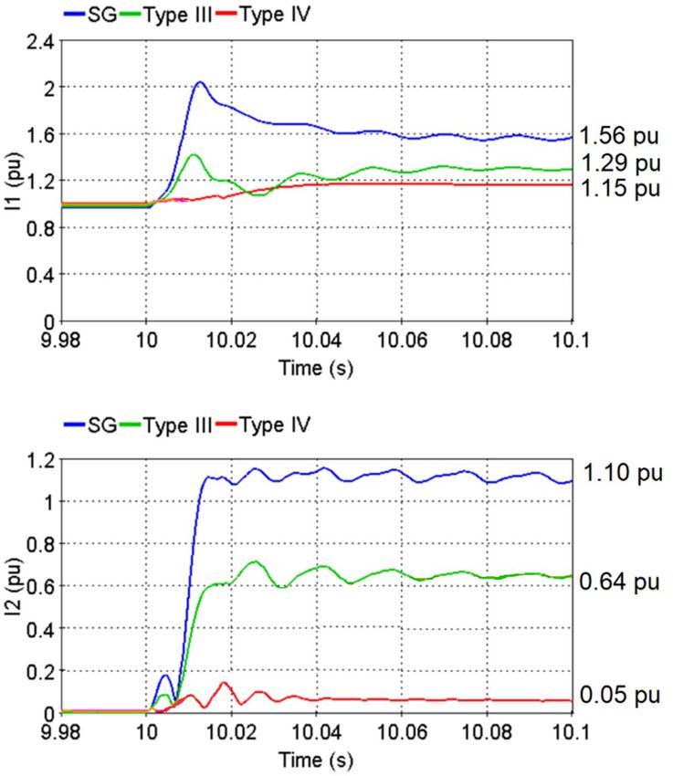
14 www.epri.com © 2021 Electric Power Research Institute, Inc. All rights reserved.Fault Current Amplitude
+ seq current - seq current
Generator type
I1 (pu) I2 (pu)
Synchronous Generator 1.56 1.10
Type III WTG 1.29 0.64
Type IV WTG 1.15 0.05
15 www.epri.com © 2021 Electric Power Research Institute, Inc. All rights reserved.Fault Current Power Factor/Phase Angle
Angle(I2)
Generator type
(degrees)
Synchronous Generator 90 (leading)
Type III WTG 105 (leading)
Type IV WTG -95 (lagging)
16 www.epri.com © 2021 Electric Power Research Institute, Inc. All rights reserved.IBR Negative Sequence Fault Current
▪ IBRnegative sequence fault current depends on the
inverter control
▪ For
Type IV WTG & Solar PV: typically low negative
sequence current, but varies among inverter
manufacturers
▪ Type III WTG injects negative sequence current
▪ Noindustry standardization (topic under IEEE
P2800), only few exceptions
– German grid code requires negative sequence fault current
injection
▪ Negative sequence current control:
– Coupled Sequence Control (CSC): Elimination of negative
sequence current injection
– Decoupled control: Negative sequence current injection based
on grid code/control logic, e.g. German Grid code Source: Dominion Energy
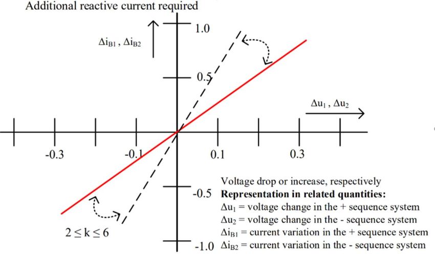
17 www.epri.com © 2021 Electric Power Research Institute, Inc. All rights reserved.German Grid Code
VDE-AR-N 4120
▪ Reactive negative sequence current
injection proportional to the negative
sequence voltage
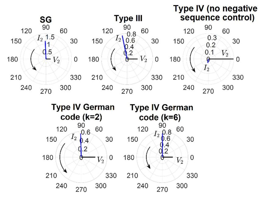
▪ Gain/Slope: 2German Grid Code – Demonstrating Results
+ seq current - seq current
Generator type
I1 (pu) I2 (pu)
Synchronous generator 1.56 1.10
Type III WTG 1.29 0.64
Type IV WTG
1.15 0.05
(No - seq control)
Type IV WTG (German
0.82 0.48
code control with k=2)
Type IV WTG (German
0.66 0.64
code control with k=6)
19 www.epri.com © 2021 Electric Power Research Institute, Inc. All rights reserved.German Grid Code – Demonstrating Results
Angle(I2)
Generator type
(degrees)
Synchronous Generator 90 (leading)
Type III WTG 100 (leading)
Type IV WTG (no –seq
-95 (lagging)
control)
Type IV WTG (German
90 (leading)
code with k=2)
Type IV WTG (German
90 (leading)
code with k=6)
20 www.epri.com © 2021 Electric Power Research Institute, Inc. All rights reserved.Summary & Conclusions
▪ Fault
current response of an IBR is different from that of a traditional synchronous
generator:
– Lower amplitude
– Typically small negative-sequence current contribution
– Dynamically changing power factor angle.
▪ Increased uptake of IBRs changes the short-circuit behavior of the power system.
The main question is:
How does the increased uptake of IBRs impact the
performance of legacy protective relays?
21 www.epri.com © 2021 Electric Power Research Institute, Inc. All rights reserved.Protection Guidelines 22 www.epri.com © 2021 Electric Power Research Institute, Inc. All rights reserved.
Impact on System Protection
 • Protection system performance evaluation: Study relay response & identify relay misoperation scenarios with high IBR
   penetration.
 • Guideline document: Provide recommendations and study practices to protection engineers to prevent relay
   misoperation/miscoordination.
                                                                                                                      Impacted protection functions

                                                                                                                            Power swing protection
                                                                                                                               ROCOF protection
                                                                                                                          Negative sequence elements
                                                                                                                             Directional elements
                                                                                                                            Overcurrent protection
                                                                                                                               Fault identification
                                                                                                                                Pilot protection
                                                                                                                             Differential protection
                                                                                                                              Distance protection

23                 www.epri.com                 © 2021 Electric Power Research Institute, Inc. All rights reserved.
Power Swing Protection
Inner Outer
Cause of potential misoperation jX
blinder blinder
▪ Increased rate of change of swing impedance due to fast IBR Δt
controls & reduced inertia Unstable
swing Stable
▪ Changed swing impedance trajectory due to IBR dynamics Z2 swing
Z1
Impacted power swing protection functions
▪ Power Swing Blocking (PSB): Power swing misinterpreted Line
as fault, undesired line trip. R
▪ Out-of-Step Tripping (OST): Stable swing misinterpreted as
unstable, unnecessary partitioning of the system
▪ Electrical Center (EC): Changed location.
Recommendations
▪ Reduce the PSB time delay to detect faster swings under high
levels of IBRs.
▪ Reduce the reach of the inner blinder to account for the most
severe stable swing under high levels of IBRs.
▪ Re-calculate the location of EC under IBRs to find the new
optimal location for the implementation of the OST function. PSB misoperation due to IBR
Reference: Impact of Inverter-Based Resources on Power Swing and Rate of Change of Frequency Protection, EPRI, Palo Alto, CA, 2020, 3002016198.
24 www.epri.com © 2021 Electric Power Research Institute, Inc. All rights reserved.IBR Modeling Requirement for Power Swing Studies
EMT-type IBR model Stability-type IBR model
• Detailed representation • Simplified representation
• Offer the highest accuracy, wideband • Capture limited dynamics typical to stability studies
• Computation time: high • Computation time: low
▪ Objective 25% IBR 50% IBR
– Establish IBR modeling requirements for
power swing protection studies.
▪ Scope
– Cross-examination of two IBR models:
▪ EMTP model
▪ 2nd generation generic WECC models
▪ Observations & conclusions
– Existing stability-type inverter models can PSB time delay
provide consistent power swing simulation Generation Scenario (cycles)
results compared with EMT models. EMTP Stability-type
(i) No IBR 8.5 8.1
– As IBR level increases, need to improve the
(ii) 25% IBR 6.1 6.4
consistency of the two models. (iii) 50% IBR 4.3 6.4
Reference: Impact of Inverter-Based Resources on Power Swing and Rate of Change of Frequency Protection, EPRI, Palo Alto, CA, 2020, 3002016198.
25 www.epri.com © 2021 Electric Power Research Institute, Inc. All rights reserved.ROCOF Protection
Cause of potential misoperation EIRGrid RoCoF 1Hz/s Program
▪ Increased Rate-of-change-of-frequency
(ROCOF) due to reduced system inertia
under IBRs
Impacted protection function
▪ ROCOF protection may misinterpret the
high ROCOF as an islanding event and
unintentionally trip generators/IBRs.
▪ UFLS also affected.
Recommendations
▪ Conventional SGs and IBRs need to
withstand higher ROCOF under IBRs
and hence relay settings need to be
adjusted (e.g., National Grid UK revised
code increases ROCOF from 0.125Hz/s
to 1Hz/s, EirGrid from 0.5Hz/s to 1Hz/s).
▪ Synchronous inertia solutions (e.g. inertia
floor) or asynchronous inertia solutions
Reference: Impact of Inverter-Based Resources on Power Swing and Rate of Change of Frequency Protection, EPRI, Palo Alto, CA, 2020, 3002016198.
26 www.epri.com © 2021 Electric Power Research Institute, Inc. All rights reserved.Negative Sequence Quantities-Based Protection
Cause of potential misoperation
▪ Low I2 contribution of IBRs, depending on IBR type & control
scheme.
▪ Changed I2 power factor due to IBR controls.
Impacted protection functions
▪ Negative-sequence overcurrent may not pick up.
▪ Directional negative-sequence overcurrent may incorrectly
determine fault direction (due to changed I2/V2 angle)
Recommendations
▪ Reduce pickup threshold setting of overcurrent relay
▪ IBR reactive I2 injection (e.g., VDE-AR-N 4120 German code)
misoperation
misoperation
misoperation
Reference: Impact of Inverter-Based Resources on Protection Schemes Based on Negative Sequence Components, EPRI, Palo Alto, CA, 2019, 3002016197.
27 www.epri.com © 2021 Electric Power Research Institute, Inc. All rights reserved.Impact of the German Grid Code
Objective: Study the impact of IBR I2 control on the
performance of protection elements based on negative-
sequence quantities.
Conclusion:
• Potential protection misoperation under GSC Coupled-
Sequence Control (CSC) mode due to I2 suppression.
• Reduced likelihood of protection misoperation with GSC
operating under the German code (VDE-AR-N 4120)
control mode.
Type 4 – Type 4 –
Traditional CSC control German code control
AG fault
Reference: System Protection Guidelines for Systems with Inverter Based Resources: Performance of Line Current Differential, Phase Comparison, Negative Sequence, Communication-
Assisted, and Frequency Protection Schemes Under Inverter-Based Resources and Impact of German Grid Code, EPRI, Palo Alto, CA: 2019. 3002016196. 28
28 www.epri.com © 2021 Electric Power Research Institute, Inc. All rights reserved.Fault Identification Logic
Cause of potential misoperation
▪ Changed I2 power factor due to IBR controls.
Impacted protection functions
▪ Changed I2/I0 angle may cause the FID to incorrectly
determine faulted phase
CG fault
Recommendations
▪ IBR reactive I2 injection (e.g., VDE-AR-N 4120 German code)
Type IV WTG Type IV WTG under the German
SG
misoperation code
Reference: Impact of Inverter-Based Resources on Protection Schemes Based on Negative Sequence Components, EPRI, Palo Alto, CA, 2019, 3002016197.
29 www.epri.com © 2021 Electric Power Research Institute, Inc. All rights reserved.Communication Assisted Protection
Cause of potential misoperation
▪ The changed I2 power factor may lead to misoperation of the
directional element; the impacted relay communicates an
incorrect permissive trip/block signal to the remote relay, thus
causing an incorrect trip decision.
Impacted communication-assisted schemes
▪ POTT, PUTT, DCB, and DCUB
Recommendations
▪ IBR reactive I2 injection (e.g., VDE-AR-N
4120 German code)
▪ POTT scheme with zero-sequence and echo
logic to provide ground fault protection.
Reference: Protection Guidelines for Systems with High Levels of Inverter Based Resources, EPRI, Palo Alto, CA: 2018. 3002013635.
30 www.epri.com © 2021 Electric Power Research Institute, Inc. All rights reserved.Line Distance Protection
Distanc
Cause of potential misoperation
e relay
▪ Low fault current amplitude due to IBRs may lead to lack of
enough supervising current, thus leading to failure to trip.
▪ Dynamically varying source impedance (and angle) of IBRs
may cause unpredictable and inconsistent dynamic expansion
of mho circle, thus leading to reduced reach accuracy and risk
of over- or under-reach.
Impacted protection functions
▪ Negative-sequence overcurrent may not pick up.
▪ Directional negative-sequence overcurrent may incorrectly Z1
determine fault direction (due to changed I2/V2 angle)
Recommendations
▪ Minimally set phase overcurrent supervision.
▪ Provide IBR dynamic I1 or I2 reactive current injection together
with additional countermeasures to attain an acceptable level
of phase distance reliability.
▪ Use zero sequence overcurrent protection for ground fault
protection (assuming the IBR to be connected through a
transformer that is a source of I0).
31 www.epri.com © 2021 Electric Power Research Institute, Inc. All rights reserved.Memory Polarized Zero Sequence Directional Element
Cause of potential misoperation
▪ Faster IBR controls and reduced inertia may cause a shift in
the phase angle of the short-circuit voltage with respect to that Distanc
of the memory voltage, leading to an incorrect directionality e relay
decision.
Impacted protection functions
▪ Memory polarized zero sequence directional element may
make an incorrect directionality decision.
Recommendations
▪ Force self-polarization when the phase angle shift exceeds a
pre-specified threshold.
▪ Apply memory voltage angle compensation whereby the phase
angle of the locked memory voltage is automatically
compensated with a supplemental phase shift quantity.
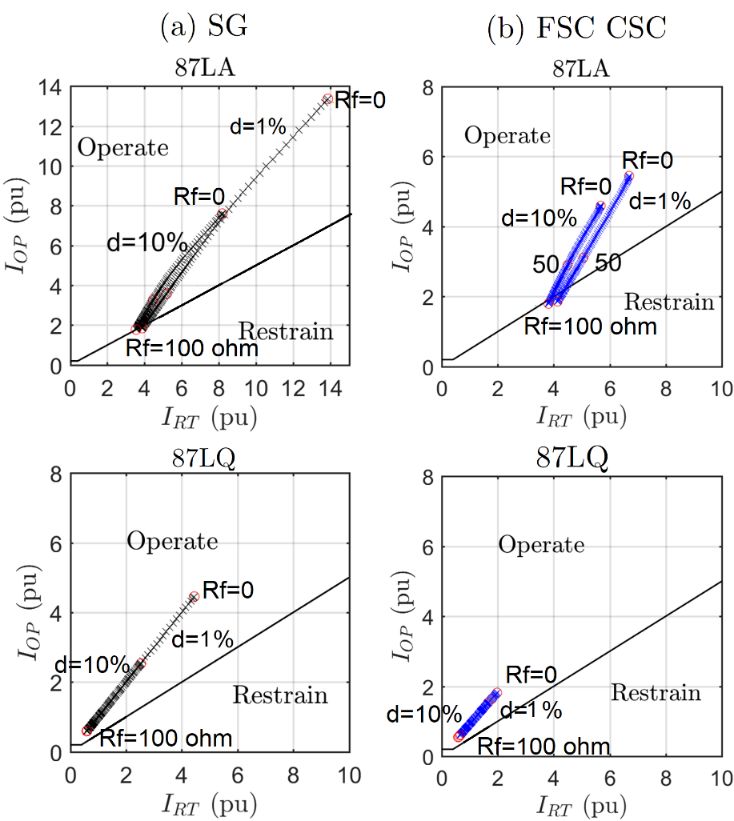
32 www.epri.com © 2021 Electric Power Research Institute, Inc. All rights reserved.Line Current Differential Protection
Cause of potential misoperation
▪ The lower fault current amplitude and dynamically changing
phase angle may cause an LCD relay to encounter different
current flow patterns compared to SGs, thus causing it not to
pick up an internal fault.
Impacted protection functions
▪ Alpha Plane LCD is prone to misoperation
▪ Traditional LCD seems to be immune
Recommendations
▪ Provide IBR dynamic I1 or I2 reactive current injection.
Reference: System Protection Guidelines for Systems with Inverter Based Resources: Performance of Line Current Differential, Phase Comparison, Negative Sequence, Communication-
Assisted, and Frequency Protection Schemes Under Inverter-Based Resources and Impact of German Grid Code, EPRI, Palo Alto, CA: 2019. 3002016196.
33 www.epri.com © 2021 Electric Power Research Institute, Inc. All rights reserved.Line Current Differential Protection
SG Type IV WTG
Type IV WTG German code
ABG
Reference: System Protection Guidelines for Systems with Inverter Based Resources: Performance of Line Current Differential, Phase Comparison, Negative Sequence, Communication-
Assisted, and Frequency Protection Schemes Under Inverter-Based Resources and Impact of German Grid Code, EPRI, Palo Alto, CA: 2019. 3002016196.
34 www.epri.com © 2021 Electric Power Research Institute, Inc. All rights reserved.Phase Comparison Protection
Cause of potential misoperation
▪ The dynamically changing phase angle under IBRs may produce
a spurious shift in the phase angle of line terminal currents,
potentially causing PC misoperation (internal fault not detected).
SG FSC WTG CSC FSC WTG German
Misoperation
35 www.epri.com © 2021 Electric Power Research Institute, Inc. All rights reserved.Summary & Conclusions
▪ Increased uptake of IBR may negatively impact the performance of traditional
protective relays.
▪ These issues stem off from different fault current characteristics of IBRs:
– Low amplitude fault current
– Dynamically changing fault current power factor
– No negative sequence fault current contribution
▪ Emerginggrid codes & IBR interconnection requirements may address some of
the misoperation challenges.
– Inverternegative sequence current injection may address such misoperations, but may also
lead to other protection challenges (eg positive sequence overcurrent protective relay
element.)
36 www.epri.com © 2021 Electric Power Research Institute, Inc. All rights reserved.References Journal Publications 1. R.M. Furlaneto, I. Kocar, A. Grilo-Pavani, U. Karaagac, A. Haddadi, and E. Farantatos, “Short Circuit Network Equivalents of Systems with Inverter-Based Resources,” Electric Power Systems Research, Volume 199, Page 107314, October 2021. 2. M. Berger, I. Kocar, E. Farantatos, and A. Haddadi, “A Dual Control Scheme for Grid Tied Battery Energy Storage Systems to Comply with Emerging Grid Codes,” Journal of Modern Power Systems and Clean Energy, Accepted, July 2021. 3. M. Berger, I. Kocar, E. Farantatos, and A. Haddadi, “Modeling of Li-ion Battery Energy Storage Systems (BESSs) for Grid Fault Analysis,” Electric Power Systems Research, Volume 196, Page 107160, July 2021. 4. A. Haddadi, E. Farantatos, I. Kocar, and U. Karaagac, “Impact of Inverter Based Resources on System Protection,” Energies Journal, Volume 14, Number 4, page 1050, https://doi.org/10.3390/en14041050, Feb. 2021. 5. A. Haddadi et al, “System Strength,” CIGRE Science and Engineering Journal, Volume 20, Pages 5-26, February 2021. 6. A. Haddadi, M. Zhao, I. Kocar, U. Karaagac, K. W. Chan and E. Farantatos, “Impact of Inverter-Based Resources on Negative Sequence Quantities-Based Protection Elements,” IEEE Transactions on Power Delivery, Volume 36, Issue 1, Pages 289-298, February 2021. 7. A. Haddadi, I. Kocar, J. Mahseredjian, U. Karaagac, and E. Farantatos, “Negative Sequence Protection Under Inverter-Based Resources– Challenges and Impact of the German Grid Code,” Electric Power Systems Research, volume 88, pages 106573, November 2020. 8. A. Haddadi, I. Kocar, T. Kauffmann, U. Karaagac, E. Farantatos, and J. Mahseredjian, “Field Validation of Generic Wind Park Models Using Fault Records,” Journal of Modern Power Systems and Clean Energy, volume 7, issue 4, pages 826–836, July 2019. 9. A. Haddadi, I. Kocar, U. Karaagac, H. Gras, and E. Farantatos, “Impact of Wind Generation on Power Swing Protection,” IEEE Transactions on Power Delivery, volume 34, issue 3, pages 1118–1128, January 2019. 10.T. Kauffmann, U. Karaagac, I. Kocar, S. Jensen, E. Farantatos, A. Haddadi, and J. Mahseredjian, “Short-circuit model for Type-IV wind turbine generators with decoupled sequence control”, IEEE Transactions on Power Delivery, DOI: 10.1109/TPWRD.2019.2908686, Apr. 2019 11.T. Kauffmann, U. Karaagac, I. Kocar, S. Jensen, J. Mahseredjian, and E. Farantatos “An accurate Type III wind turbine generator short circuit model for protection applications”, IEEE Transactions on Power Delivery, vol. 32. No. 6, Dec 2017 37 www.epri.com © 2021 Electric Power Research Institute, Inc. All rights reserved.
References
     Conference Papers
     1. A. Haddadi, M. Zhao, I. Kocar, E. Farantatos, and F. Martinez, “Impact of Inverter-Based Resources on Memory-Polarized Distance
        and Directional Protective Relay Elements,” 2020 52nd North American Power Symposium (NAPS), Tempe AZ, pages 1–6, April
        2021.
     2. A. Haddadi, I. Kocar, J. Mahseredjian, U. Karaagac, and E. Farantatos, “Performance of Phase Comparison Line Protection Under
        Inverter-Based Resources and Impact of the German Grid Code,” IEEE Power and Energy Society General Meeting (PESGM),
        Montreal, August 2020 (Best paper award).
     3. A. Haddadi, I. Kocar, J. Mahseredjian, U. Karaagac, and E. Farantatos, “Negative Sequence Protection Under Inverter-Based
        Resources–Challenges and Impact of the German Grid Code,” Power Systems Computation Conference (PSCC), Porto, Portugal,
        June 2020.
     4. A. Haddadi, M. Zhao, I. Kocar, E. Farantatos, and F. Martinez, “Impact of Inverter-Based Resources on Memory-Polarized Distance
        and Directional Protective Relay Elements,” Submitted to 2020 North American Power Symposium (NAPS), Tempe AZ, October
        2020.
     5. U. Karaagac, T. Kauffmann, I. Kocar, H. Gras, J. Mahseredjian and E. Farantatos, "Phasor domain modeling of Type IV wind turbine
        generator for protection studies," Proc. 2015 IEEE PES General Meeting, Denver, CO, 26-30 July 2015.
     6. T. Kauffmann, U. Karaagac, I. Kocar, H. Gras, J. Mahseredjian, and E. Farantatos, “Phasor domain modeling of Type III wind turbine
        generator for protection studies,” Proc. IEEE PES General Meeting, Denver, CO, USA, Jul. 2015.

38                      www.epri.com                    © 2021 Electric Power Research Institute, Inc. All rights reserved.
References
EPRI Reports
1. Advanced Short-Circuit Modeling, Analysis and Protection Schemes Design for Systems with Renewables: NYPA Case Study, EPRI, Palo Alto,
CA: 2021, 3002020448.
2. Equivalencing Methods of Systems with High Levels of Inverter Based Resources for Short-Circuit Studies, EPRI, Palo Alto, CA: 2020,
3002018697.
3. Protection Guidelines for Systems with Inverter Based Resources, EPRI, Palo Alto, CA: 2020, 3002018717.
4. Battery Energy Storage Systems Modeling for Short-Circuit Studies, EPRI, Palo Alto, CA: 2020, 3002018696.
5. Pre-Software: Voltage Controlled Current Source Parameterization Tool (VCCS) v1.0 Tool, EPRI, Palo Alto, CA: 2020, 3002018716.
6. System Protection Guidelines for Systems with Inverter Based Resources: Performance of Line Current Differential, Phase Comparison,
Negative Sequence, Communication-Assisted, and Frequency Protection Schemes Under Inverter-Based Resources and Impact of German
Grid Code, EPRI, Palo Alto, CA, 2019, 3002016196.
7. Impact of Inverter-Based Resources on Power Swing and Rate of Change of Frequency Protection, EPRI, Palo Alto, CA, 2020, 3002016198.
8. Impact of Inverter-Based Resources on Protection Schemes Based on Negative Sequence Components, EPRI, Palo Alto, CA, 2019,
3002016197.
9. Protection Guidelines for Systems with High Levels of Inverter Based Resources, Palo Alto, CA: 2018. 3002013635.
10.Short-Circuit Phasor Models of Inverter-Based Resources for Fault Studies - Model Validation Case Studies, Palo Alto, CA: 2018,
3002013634.
11.Short-Circuit Phasor Models of Converter Based Renewable Energy Resources for Fault Studies, Palo Alto, CA: 2017. 3002010936.
39 www.epri.com © 2021 Electric Power Research Institute, Inc. All rights reserved.Together…Shaping the Future of Electricity 40 www.epri.com © 2021 Electric Power Research Institute, Inc. All rights reserved.
You can also read