Lateral Buckling Theory and Experimental Study on Pipe-in-Pipe Structure - MDPI
←
→
Page content transcription
If your browser does not render page correctly, please read the page content below
metals
Article
Lateral Buckling Theory and Experimental Study on
Pipe-in-Pipe Structure
Zechao Zhang 1 , Hongbo Liu 1 and Zhihua Chen 1,2, *
 1   Department of Civil Engineering, Tianjin University, Tianjin 300072, China; zhanghuifine@126.com (Z.Z.);
     hb_liu2008@163.com (H.L.)
 2   Key Laboratory of Coast Civil Structure and Safety, Ministry of Education, Tianjin University,
     Tianjin 300072, China
 *   Correspondence: zhchen@tju.edu.cn; Tel.: +86-136-6201-1823

 Received: 16 January 2019; Accepted: 2 February 2019; Published: 4 February 2019

 Abstract: With the increasing depth of marine oil and gas exploitation, more requirements have been
 proposed on the structure of deep-sea oil pipelines. The influencing factors of lateral buckling of a
 pipe-in-pipe (PIP) structure containing initial imperfections and its critical force were investigated
 in this study by conducting an experiment, a finite element analysis, and a theoretical derivation.
 The change laws on the influence of initial imperfections of the PIP structure during thermal loading
 were revealed through an experimental study by using imperfection amplitude and wavelength
 as parameters. Appropriate finite element models were established, and the influences of initial
 imperfections, pipe-soil interaction, and the height and the number of centralizers on the global
 buckling critical force of the PIP structure were analyzed. The formulas of global buckling critical
 force of inner and outer pipes and that under pipe-soil interaction was obtained by using a theoretical
 derivation method. A comparative verification with experimental and finite element (FE) models
 result was conducted, which provided a corresponding basis for steel pipeline design.

 Keywords: pipe-in-pipe (PIP) structure; global buckling; critical axial force; experimental study;
 finite element (FE) model

1. Introduction
     With the gradual increase of marine oil and gas exploitation depth, high temperature, high
pressure, corrosion effect, and ocean currents are all extreme conditions experienced by subsea
pipelines, which then result in enormous economic losses and catastrophic and irreversible
environmental pollution [1]. Considering that the distance between deep-sea oil pipelines are usually
large, which are generally over tens of kilometers, pipelines must provide excellent thermal insulation
properties to prevent crude oil from wax deposition. Traditional single-layer insulation pipelines are
becoming increasingly incapable of satisfy rigorous thermal insulation requirements. A pipe-in-pipe
(PIP) structure consists of rigid outer pipe, inner pipe, and centralizer, which are connected using
specialized joint nodes (bulkheads) at a certain distance [2]. Thermal insulation materials (materials
without structural strength, such as particles, foams, and aerogel) are added in the circumferential
space formed between the inner and outer pipes. Considering that inner and outer pipes have different
force transfer patterns, the PIP structure can be subdivided into compliant and non-compliant types [3].
     The global buckling of subsea pipelines belongs to the buckling strength of axial compression
member problem; however, the pipe-soil interaction between the seabed and PIP structure and
the internal interaction inside the PIP structure makes this a different problem [4]. Similar to
traditional pipelines, the PIP structure experiences the global buckling problem. However, the axial

Metals 2019, 9, 185; doi:10.3390/met9020185                                      www.mdpi.com/journal/metals
Metals 2019, 9, 185                                                                                  2 of 16

force computation of the PIP structure under the pressure effect is more complicated than that in a
single-layer pipeline because the inner and outer pipes of the PIP structure work as a whole.
      In the terms of theoretical studies, Liu [5] studied the mechanical behavior of high-strength
X80 pipeline when subjected to strike-slip fault displacements. Goplen and Fyrileiv [6] indicated
that the analysis and application of the PIP structure depend on taking it as a system rather than
as two connected pipes. Sriskandarajah [2] analyzed the force transfer mechanism of the outer
pipe in the PIP structure and the probability of global buckling and provided an approximate
expression of the effective axial force of the PIP structure. However, this expression neglects the
influences of the collaborative working mechanism of inner and outer pipes and pipe-soil interaction.
Zhao [7] used finite element technology to analyze the global lateral buckling performances of
compliant- and non-compliant-type PIP structures and considered the initial imperfections and
nonlinear characteristics of the PIP structure in the calculation; however, the author did not provide a
computational formula of corresponding buckling critical force of the PIP structure. Vaz and Patel [8]
established a differential control equation of global lateral buckling of the non-compliant type PIP
structure based on a single-beam differential control equation. However, the study by Vaz and Patel
neglects the two important factors in the theoretical framework of overall buckling, namely, frictional
force and initial imperfections. Therefore, their analysis was only the first step in conducting a global
buckling analysis of the PIP structure, and a large quantity of work remains to be improved.
      Experimental studies have mainly concentrated on single-layer pipelines, and few studies have
been reported on the buckling characteristics of the PIP structure. Allan [9] investigated the global
buckling behavior of elastic steel bars on rigid basis and verified the sensitivity of their buckling
secondary to imperfections. Duan [10] et al. used a small-size model and a mechanical loading mode to
evaluate the global buckling of a PIP structure and obtained the axial force-displacement relationship
and critical axial force during the buckling process. Maltby and Calladine [11] evaluated the vertical
buckling problems of buried pipelines. Their experimental results re-verified the sensitivity of global
pipeline buckling secondary to imperfections, and no “combinational buckling patterns”, namely,
simultaneous existence of vertical buckling and lateral buckling, were observed and described in the
theoretical solutions. Taylor and Tran [12] published a paper in 1996 in which they introduced their
global buckling experimental device of the pipeline and observed that several imperfection patterns
would reduce the vertical buckling critical temperature by 50%. Loen [13] conducted an experimental
study on the vertical buckling of buried and grooved pipelines and assessed the vertical buckling
performances of buried pipelines under different soil conditions and different imperfection patterns.
Karampour [14] investigated the propagation buckling of subsea PIP structures under hydrostatic
pressure and obtained new buckling modes in hyperbaric chamber tests of PIP structures. Alrsai [15]
studied the buckling mechanisms in PIP structures with thin and moderately thin carrier pipes with a
diameter-to-thickness (D0 /t0 ) ratio in the range of 26–40, but the global buckling of the PIP structure
was not mentioned.
      Thus, previous studies have focused on theoretical studies, and the proposed computational
formulas of buckling critical force of the PIP structure have not considered the influences of initial
imperfections, pipe-soil interaction, and centralizers between the inner and outer pipes, for which
they have certain limitations. Moreover, experimental studies have been scarcely reported in articles.
Therefore, experiments were conducted with nine specimens with different initial wavelengths and
amplitudes. Then, based on these experiments, the influence of the initial imperfections on the critical
axial force, the critical temperature difference and critical displacement are discussed. In addition,
a finite element model was established to simulate the experimental specimens. Based on a nonlinear
finite element analysis, a parametric study was conducted to analyze the influence of several variables
in the lateral buckling of the PIP structure, namely, the initial imperfections, the pipe-soil interaction,
and the height and number of centralizers. The obtained results are presented and discussed.
Finally, an analytical equation to compute the lateral buckling axial force is derived and verified based
on the obtained experimental and numerical results. By comparing results with a practical project in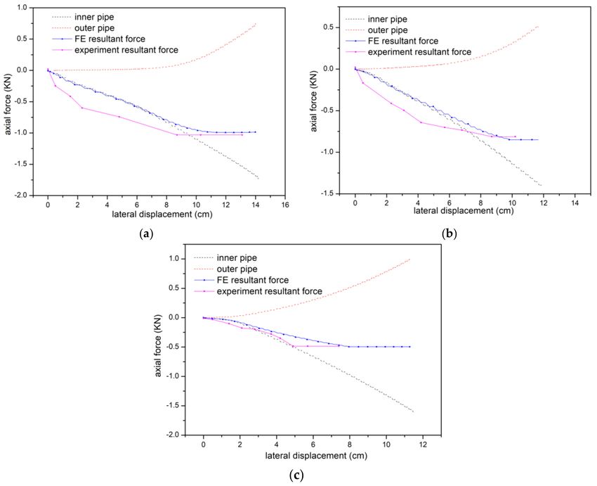
Metals 2019, 9, 185                                                                                              3 of 16

South China Sea, the formula is shown to have high accuracy, which can provide a corresponding
basis for steel pipeline design.

2. Global Buckling Experiment of the PIP Structure

2.1. Experimental Design
      Considering that the elasticity modulus and density of aluminum alloy materials are 1/3 of those of
steel materials and their thermal expansion coefficient is twice of that of steel materials, 6061-T6 aluminum
alloy material can be used to achieve improved monitoring of the experimental phenomena in comparison
to steel materials of the same size [16]. The material properties are listed in Table 1.

                                             Table 1. Material properties.

                                         Young’s                                          Thermal Expansion
           Alloy Designation                                          Poisson’s Ratio
                                       Modulus (GPa)                                      Coefficient (mm/◦ C)
                  6061-T6                    69.82                             0.3           1.881 × 10⁻⁵

     The length of the PIP structure is 9000 mm due to the size limitation of the experimental sand tank.
Lateral initial imperfections are set at the midspan position, which are simulated by using triangular
sine curves. Different imperfection wavelengths and amplitudes based on a sine function-based
imperfection pattern given by Maltby and Calladine can be expressed as [11]:

                                                                      πx
                                                     l = v0 sin                                                     (1)
                                                                      l0

     The initial imperfections on the inner pipes were the same as that on the outer pipes in one group
of experiments. They were processed using a numerical control pipeline bender to ensure that they
were a perfect sine function, as in Equation (1), and that the pipelines were eccentric on the machine.
As shown in previous studies [17], the global buckling of pipelines occurs at a small part of a full-length
range, where minimum l0 is l/5. By considering the machining accuracy, the minimum l0 was set as
2000 mm and minimum v0 was set to 20 mm to avoid the effect on buckling and post-buckling of PIP
structures caused by initial imperfections. The thickness of inner and outer pipes of the PIP structure
was 3 mm, and their diameters were 36 mm and 62 mm, respectively. The centralizers were arranged
every other 500 mm along the axial direction between the inner and outer pipes, and aluminum silicate
cloth was filled between the inner and outer pipes as the thermal insulation material. The PIP structure
was divided into 3 groups based on imperfection wavelength l0 , and the model parameters are shown
in Table 2.

                            Table 2. Initial imperfection design of the experimental models.

                 Group              Specimen No.             Wavelength l0              Amplitude v0 (mm)
                                      S1-1000-20                       1000                     20
                 Group I              S2-1000-30                       1000                     30
                                      S3-1000-40                       1000                     40
                                      S4-2000-20                       2000                     20
                Group II              S5-2000-30                       2000                     30
                                      S6-2000-40                       2000                     40
                                      S7-4000-40                       4000                     40
                Group III             S8-4000-60                       4000                     60
                                      S9-4000-80                       4000                     80

      An oil temperature control loading device was used for loading, and this device mainly included a
test sand tank as shown in Figure 1a, a hot-oil circulation heating control device which can display the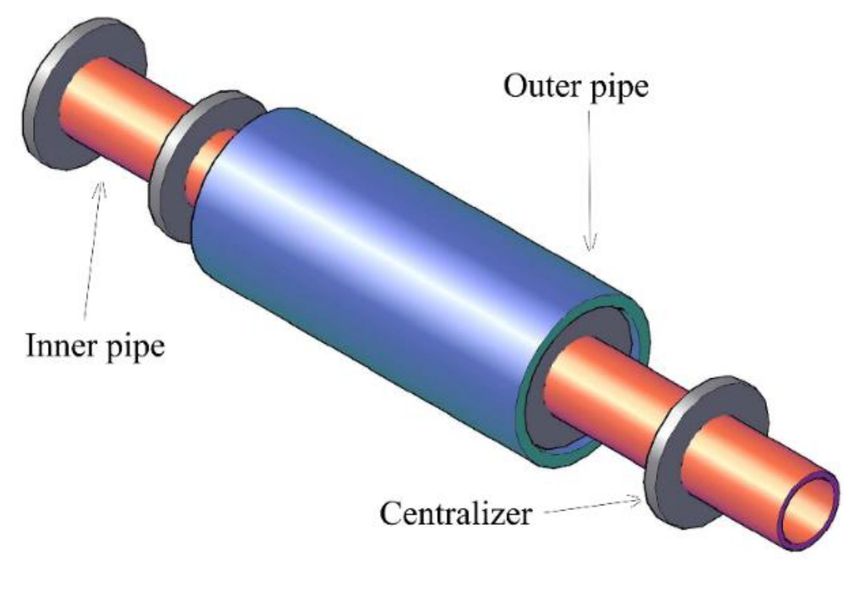
Metals 2019, 9, 185                                                                                    4 of 16

temperature of oil and the pressure in the inner pipe as shown in Figure 1b, and a fastening device at
the pipe ends as shown in Figure 1c. A monotonous temperature loading system was used to gradually
increase temperature from outside atmospheric temperature T0 until buckling of the PIP structure
occurs, and a loading temperature step was set every other 10 ◦ C. The strain gauge and displacement
data were acquired before and post-buckling. Figure 1d shows a real example of the end structure of
the PIP structure. At the ends of the PIP structure, the outer pipe is connected to the end fastening
device through the adapter ring, the inner pipe is directly screwed with the oil supply hole, and neither
inner nor outer pipes can move along the axial direction but can rotate. PIP structure buckling occurred
in the loading device due to thermal expansion and the applied longitudinal constraints, and no other
external forces were applied.

      Figure 1. Experimental device: (a) hot-oil circulation heating control device; (b) test sand tank;
      (c) fastening device at pipe ends; (d) structure of pipe ends; (e) layout plan of experimental
      loading device.

2.2. Analysis of Experimental Results
     By analyzing the results of strain, temperature difference of inner pipe, lateral displacement
of the midpoint on the outer pipe, we defined when the global buckling happened. The axial
force of the PIP remain unchanged, and the corresponding critical temperature and displacement
were measured. The critical axial force, critical temperature, and displacement under the buckling state
of the experimental PIP structure are shown in Table 3. For the first group of pipelines, imperfection
increases from 2 cm to 50% and 100%, and the temperature difference reduces by 1.7% and 7.1%,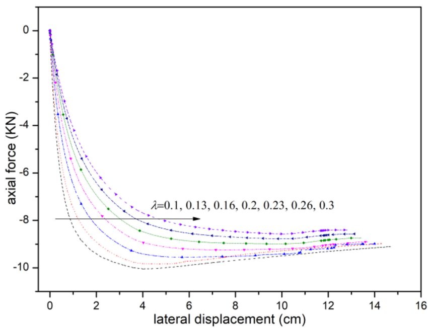
Metals 2019, 9, 185                                                                                     5 of 16

respectively, which indicates that the increased imperfection amplitude does not have an obvious effect
on reducing the critical temperature difference. The critical temperature differences of the pipelines
in the second group are 11.4 ◦ C, 12.1 ◦ C, and 12.4 ◦ C when l0 increases from 1000 mm to 2000 mm
compared with the first group of pipelines. Thus, the increase of pipeline length l0 has a remarkable
effect on critical temperature difference. v0 /l0 = λ is defined, S1-1000-20, S-2000-40, and S-4000-80
are used, and critical temperature differences at the time are 16.4 ◦ C and 17.9 ◦ C, which indicate that
the change of critical pipeline buckling temperature exerts the main effect and effectively reduces the
critical pipeline buckling temperature with the increase of l0 .

                             Table 3. Experimental result of different specimens.

                                                       Critical temperature               Critical
          Specimen No.      Critical axial force (N)
                                                         difference (◦ C)           displacement (mm)
            S1-1000-20              −1251.8                     56.6                      118.3
            S2-1000-30              −943.4                      55.6                      115.3
            S3-1000-40              −899.6                      52.6                      110.6
            S4-2000-20              −760.2                      45.2                       78.5
            S5-2000-30              −550.1                      43.5                       70.2
            S6-2000-40              −510.9                      40.2                       48.7
            S7-4000-40              −417.2                      35.7                       22.3
            S8-4000-60              −333.3                      32.2                       20.3
            S9-4000-80              −270.6                      22.5                       18.4

      For pipelines with l0 = 1000 mm, pipeline buckling displacement is slightly reduced, and lateral
displacement is reduced by 4.2% with the increase of amplitude. Thus, the change on v0 does not have
an obvious effect in reducing the critical pipeline buckling force when l0 is certain. The critical pipeline
buckling displacement differences are 41.8, 45.1, and 61.0 mm with the increase of l0 from 1000 mm to
2000 mm. For the third group of pipelines, global buckling can easily occur, and the increase of pipeline
length l0 can reduce critical buckling displacement. Figure 2 shows the displacement deformation
before and after pipeline buckling. The global buckling phenomenon becomes slightly obvious with
the increase of l0 .
      The critical buckling axial forces of pipelines of the three groups are shown in Table 3. On the basis
of a comparative analysis of three specimens, S3-1000-40, S5-2000-40, and S7-4000-40 (v0 = 40 mm),
their wavelengths l0 are 1000, 2000, and 4000 mm, respectively. Pipeline l0 = 1000 mm based on
the standard, the wavelengths of S5-2000-40 and S7-4000-40 increased by 100% and 300%, and their
critical buckling axial forces reduced by 43.8% and 53.7%, respectively. Therefore, the change of the
wavelength value can obviously reduce the critical buckling axial force when the amplitude remains
unchanged. For the intra-group comparison of three groups of pipelines, the maximum differences of
critical axial forces between pipelines in each group are 351.8, 249.3, and 146.6 N, and their critical axial
forces are reduced by 28.1%, 32.7%, and 35.1%, respectively, when wavelength l0 is compared with the
critical axial forces under the minimum amplitude value of each specimen. This finding indicates that
the change of amplitude value v0 basically presents a first-order linear relation with the reduction of
critical pipeline buckling force.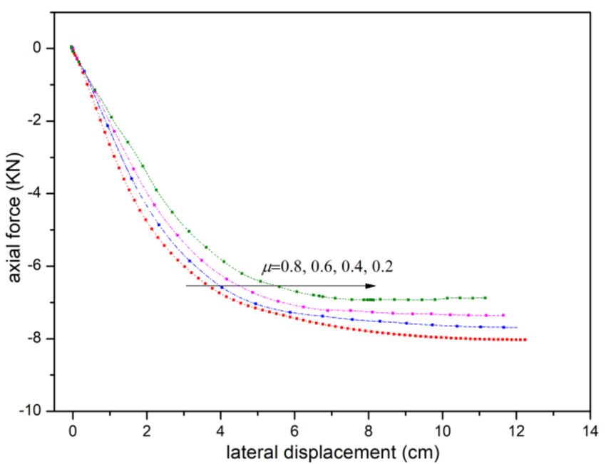
Metals 2019, 9, 185                                                                                    6 of 16

                  Figure 2. Buckling mode of the PIP structure with different initial imperfections.

3. Parameter Analysis of Global Lateral Buckling

3.1. Finite Element Modeling Method
     ABAQUS finite element software (ABAQUS 6.14-4, SIMULIA, Johnston, RI, USA) was used to
establish a finite element model of the PIP structure and to predict the global buckling performance of
the PIP structure under the effect of temperature load. As shown in Figure 3, PIPE31 units were used
to simulate the inner and outer pipes, and a single-node ITT (tube-to-tube contact element) unit was
used to simulate the contactor between the inner and outer pipes [18]. The ITT was attached to the
beam unit nodes of the inner pipe, and a virtual slip line was attached to the outer pipe, which consists
of nodes of the outer pipe. During calculation, the ITT unit detects its own normal displacement.
Normal acting and tangential frictional forces were generated between the inner and outer pipes when
the ITT contacted with the outer pipe. In the process of calculation, linear heating of the inner pipe
from 0 to 100 ◦ C temperature difference to simulates the continuous heating process of crude oil,
and the outer pipe is consistent with the project which keeps the temperature constant at 0 ◦ C.

                                Figure 3. Detailed drawing of the numerical model.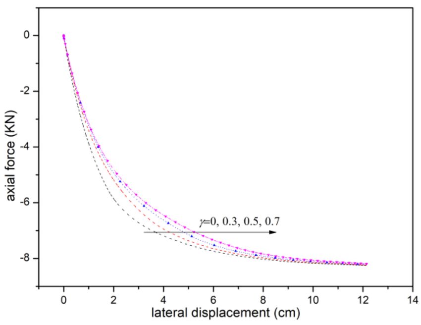
Metals 2019, 9, 185                                                                                  7 of 16

     The nonlinear SPRING1 unit was used to simulate nonlinear pipe-soil interaction.
The displacement at one end of the unit was fixed, and the other end was interconnected with
the outer pipe node. The bottom of the spring element was assumed to be rigid. A bilinear pipe-soil
interaction model was used to simulate the pipe-soil interaction of horizontal displacement, as shown
in Figure 4, where H and V are the seabed resistance and underwater pipeline weight, respectively.
The relationship between H and V can be expressed as [19]:

                                                         H
                                                           =µ                                           (2)
                                                         V

                                          Figure 4. Pipe-soil interaction model.

      The global lateral buckling problem of the PIP structure belongs to a localized and nonlinear
buckling problem; that is, the local transfer of strain energy exists in the buckling process [20].
Therefore, the use of a traditional pure Newton-Raphson method in solving this results in a convergence
difficulty near the buckling point. Good solutions to this problem are through mainly using dynamic
and static methods that consider artificial numerical damping. A momentary rigid body displacement
phenomenon occurs when the inner pipe undergoes buckling and breaks from the constraint of
the outer pipe. At the same time, a certain numerical damping should be added to prevent
the singularity phenomenon of the stiffness matrix. Thus, the matrix can smoothly surpass the
buckling point, and a post-buckling analysis can be implemented. Obviously, the added artificial
damping affects the properties of the stiffness matrix itself when its value is large, which results
in the distortion of calculation results. Therefore, during the calculation process, the proportional
relationship between numerical damping dissipation energy (ALLSD) and total strain energy (ALLIE)
of the system was continuously monitored to ensure that the proportion of numerical damping
dissipation energy to total strain energy of the system did not exceed 0.5%. Specifically, the influence of
artificial numerical damping on global energy distribution of the system should be smaller than 0.5%.
Otherwise, the artificial numerical damping remarkably influences the calculation results.
      To verify the numerical analysis in this section, a comparison with the experimental pipelines
was conducted, and a corresponding numerical model was established for the calculation.
The corresponding model parameters are provided in Table 4.

                                       Table 4. Corresponding model parameters.

                                Diameter (D) (mm)                                      62
                               Diameter (d) (mm)                                        36
                             Wall thickness (t) (mm)                                     3
                          Elasticity modulus (E) (MPa)                                68,000
                                Poisson’s ratio (δ)                                     0.3
                      Linear expansion coefficient (α) (/◦ C)                      1.73 × 10⁻⁵
                         Underwater mass (W) (KN/mm)                                   300
                      Pipe–seabed frictional coefficient (µ3 )                          0.3
                          Temperature difference (◦ C)                                 100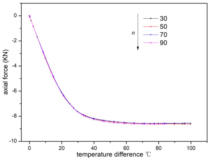
Metals 2019, 9, 185                                                                                  8 of 16

3.2. Model Verification
     To verify the accuracy of the proposed numerical model, the experimental results of S1-1000-20,
S4-2000-20, and S7-4000-40 were taken as the control group. Figure 5 shows the relationships of axial
forces of inner and outer pipes in the PIP structure with a midpoint buckling displacement. As shown
in Figure 5, the resultant force of axial forces of inner and outer pipes represents the stability of the
PIP structure. The axial force of the inner pipe gradually increases with the increase in temperature,
and the outer pipe bears tensile force, which gradually increases with the increase in temperature.
The resultant force of the inner and outer pipes gradually increases with temperature and remains
constant when the limit buckling axial force is reached. This condition indicates that the structure
experiences buckling. The critical buckling axial forces obtained in the numerical simulation are
−1.02, 0.71, and −0.47 KN; their relative errors with experimental values are all controlled within 10%,
and the change laws of resultant force curve of inner and outer pipes is identical with those shown
in the experiment. Therefore, the proposed model can capture the global buckling features of the
PIP structure.

      Figure 5. Comparison of axial force-lateral displacement curve with finite element (FE) and
      experimental results. (a) S1-1000-20; (b) S4-2000-20; (c) S7-4000-40.

3.3. Parameter Analysis
     Parameterized models are established based on the above analysis to discuss the influences
of initial imperfections, pipe-soil interaction, and the height and number of centralizers on global
buckling of the PIP structure. Initial imperfection length l0 is set to 1800 mm in this section; the length
of the PIP structure model is 5l0 , namely, 9000 mm; diameter of the outer pipe is D = 60 mm; diameter
of the inner pipe is d = 30 mm; wall thickness of the inner and outer pipe is t = 3 mm; amplitude is
Metals 2019, 9, 185 9 of 16
20 mm; and the spacing between the centralizers and outer pipe is 2 mm. These settings are taken as
the standard model.
3.3.1. Influence of Initial Imperfections
Figure 6 indicates the influence of initial imperfections on the global lateral buckling path of the
PIP structure. Two global buckling paths of the PIP structure are expressed as follows: The buckling
path is relatively gentle without any obvious buckling point when no straightness is large, such that
λ is greater than 0.2; and the buckling path has an obvious buckling point when no straightness is
small, such that λ is smaller than 0.2. The pipeline displacement rapidly increases when the critical
buckling point is crossed. This condition is because the PIP structure can be simplified into an overall
stability problem of axial compression of the PIP structure that contains initial imperfections when
other conditions are unchanged and only the size of initial imperfection is changed. On the basis of an
analysis of compression-bending members that contain initial flexural imperfections, the greater the
initial imperfection is, the smaller the critical force of the pressure bar will be. The global compression of
the inner pipe stimulates buckling of the outer pipe. The PIP structure tends to accumulate deformation
toward the midpoint imperfection due to pipe-soil interactions. For the critical imperfection length,
the tensile force of the outer pipe increases more rapidly than the pressure of inner pipe, and a
large negative force and bending moment are generated at the starting point of imperfection to
generate displacement. The growth rate of axial force of the inner pipe is higher than that of tensile
force of the outer pipe when the critical length is exceeded. The PIP structure experiences compression,
midpoint displacement becomes positive, and the PIP structure easily undergoes buckling when initial
imperfection wavelength l0 of the PIP structure is large.
Figure 6. Force-displacement curve of different λ.
3.3.2. Influence of Pipe-Soil Interaction
Pipe-soil frictional coefficients are set to 0.2, 0.4, 0.6, and 0.8. As shown in Figure 7, the frictional
force between the outer pipe and seabed increases with the increase of pipe-soil frictional coefficient,
which limits lateral displacement. The straight segment of the PIP structure has a squeezing tendency
in the buckling segment when the PIP structure undergoes global buckling, and the axial frictional force
constrains the squeezing of the straight segment to prevent buckling deformation. The frictional force
that should be overcome is greater with the increase of frictional coefficient when the PIP structure
experiences lateral buckling. At the same time, the axial force in the straight segment is greater.
Thus, the greater the pipe-soil frictional coefficient is, the greater the critical buckling axial force will be.Metals 2019, 9, 185 10 of 16
Figure 7. Force-displacement curve of different µ.
3.3.3. Influence of Height of Centralizers
The spacing of centralizers is defined as γ = (r0 − h)/ro . Figure 8 shows the axial
force-displacement curve of the inner pipe under different heights of centralizers. As shown in
the figure, the global lateral buckling of the PIP structure can be decomposed into two parts when the
spacing of centering rings is not zero. The inner pipe experiences lateral buckling, and the inner pipe
drives the outer pipe to drive lateral buckling of the entire PIP structure due to the contact between
the inner pipe and outer pipe. In the post-buckling phase, the influence of the spacing of centralizers
on buckling path of the PIP structure is minor, as shown in the figure.
Figure 8. Force-displacement curve of different γ.
3.3.4. Influence of the Number of Centralizers
The main effect of centralizers is in providing lateral forces on the inner and outer pipes during
the buckling process. The influence of the number of centering rings can be ignored in the straight
segment. The centralizers in the model present a uniform distribution along the axial direction, and the
spacing of centralizers can be changed to analyze the influence of the number of centralizers on global
buckling in the imperfection segment. On the basis of the axial force-temperature difference curve in
Figure 9, the influence of the number of centralizers is approximately zero for before and post-buckling,
which renders it negligible.Metals 2019, 9, 185 11 of 16
Figure 9. Force-displacement curve of different n.
4. Computational Formula of Lateral Buckling Axial Force
4.1. Derivation of Lateral Buckling Axial Force Formula
Based on the experimental and FE parameter analysis, we find that the initial imperfections,
pipe-soil interaction, and height of centralizers has a great influence on the PIP global buckling.
The basic constitution of the PIP structure is shown in Figure 10. As shown in the figure, the PIP
structure mainly consists of three parts: inner pipe, outer pipe, and centralizers. The centralizers
and inner pipe are welded together, which allows the inner pipe to slide along the inner wall of the
outer pipe. Meanwhile, the centralizers and outer pipe are incompletely fitted and have a certain gap.
The spacing is generally from 1 mm to 10 mm based on engineering practice. The spacing of the
centering rings is generally from 1 m to 2 m. The gap between the inner and outer pipes is generally
filled with light, low-strength, and high-performance insulation materials.
Figure 10. Constitution of the PIP structure.
Figure 11 shows the force diagram of the inner and outer pipes caused by the influence of
centralizers during the buckling process of the PIP structure. No gap exists between the inner and
outer pipes. For the PIP structure with simple supports at two ends, its lateral displacement value
along the lateral direction can be obtained based on second-order elasticity theory as follows [21]:
v0 πx
w= sin (3)
1 − Nin /Ncr l
where l0 is the length of imperfection segment of the PIP structure, v0 is the initial imperfection
amplitude, Ncr is the critical load of overall buckling of the PIP structure, and Nin is the axial force
borne by the inner pipe.Metals 2019, 9, 185 12 of 16
Figure 11. Force diagram of inner and outer pipes.
The inner and outer pipes undergo a single-wave type deformation. The contact force between the
inner and outer pipes is qt , and a concentrated force Fend is formed at the starting point of imperfection.
This is expressed as [22]:
π2 Nin v0 πx
qt = 2 · sin (4)
l 1 − Nin /Ncr l
Z l
1 π Nin v0
Fend = qt dx = · (5)
2 0 l 1 − Nin /Ncr
Mechanical equilibrium formula of the outer pipe in axial direction is:
f end µ1 + Wµ2 = Nout (6)
where
f end = Fend /n (7)
n is the number of centralizers in the imperfection segment;
Nin is the axial force of the inner pipe;
Nout is the axial force of the outer pipe;
µ1 is the frictional coefficient between the centering ring and outer pipe;
µ2 is the axial frictional coefficient between the outer pipe and seabed;
µ3 is the lateral frictional coefficient between the outer pipe and seabed;
W is the underwater self-weight of the PIP structure.
The following equations are obtained by substituting Equation (4) into Equation (5):
1 π Nin v0
· · µ + Wµ2 = Nout (8)
n l 1 − Nin /Ncr 1
µ1 πNin v0 + Wlµ2 − nNout l
Ncr = (9)
(W − nNout l ) Nin
According to a previous study [23], the following equation can be expressed as:
νin Pin Din Ain
Nin = Ein Ain α∆T − (10)
2tinMetals 2019, 9, 185 13 of 16
In the imperfection segment, the outer pipe mainly bears a frictional force between the lateral
pipeline and seabed, and the horizontal supporting force of the inner pipe is towards the outer pipe,
and the balance equation is expressed as:
Z l πx n
0
Wµ3 sin
l
dx = ∑ Fi (11)
i =1
On the basis of the balance equation of the inner pipe, we have:
n Z l
2π Nin v0
∑ Fi = 2Fend = 0
qt dx = ·
l 1 − Nin /Ncr
(12)
i =1
Thus:
l 2π Nin v0
Wµ3 = · (13)
π l 1 − Nin /Ncr
Then:
l 2 Wµ3 Nin
Ncr = (14)
l 2 Wµ3 − 2π2 v0 Nin
Ncr = Nin + Nout (15)
Formula 15 is used to represent the stability of the PIP structure [24]. The PIP structure experiences
global buckling when Ncr becomes stable, meaning the sum of Nin and Nout remains unchanged, but the
horizontal displacement of the PIP structure will keep increasing. Thus, the axial force of the outer
pipe during the buckling process is:
l 2 Wµ3
Nout = Nin −1 (16)
l 2 Wµ3 − 2π2 v0 Nin
On the basis of the analysis of Formula (14), the critical buckling forces of the PIP structure
mainly include (1) frictional force between the outer pipe and seabed; (2) imperfection wavelength
and amplitude; (3) underwater self-weight of the PIP structure; and (4) material characteristics and
wall thickness of the inner pipe. The influence of the number and height of centering rings is minor,
which is mutually verified by the finite element parameter analysis and experimental verification
and analysis.
4.2. Formula Verification
The critical buckling forces obtained in the theoretical formulas were compared with the
experimental values, as shown in Table 5. The relative error between the calculated critical buckling
axial force and experimental result is approximately 13.7%, which indicates that the formula has
high precision. The theoretical value obtained through the formula is relatively greater than the
experimental value because the PIP structure has an initial imperfection during the lateral buckling
process, which results in a certain axial component. However, this component is excluded in the
theoretical calculation.
In addition, in order to verify the reliability of the formulas, the basic model of PIP in a practical
project in South China Sea is established. The material of pipeline is X65 and the parameters are
d = 273.1 mm, D = 355.6 mm, tin = 11.1 mm, tout = 12.7 mm, E = 207,000, α = 1.17 × 10⁻¹⁵ , µ1 = 0.1,
µ3 = 0.2, l0 = 50 m, l = 900 mm. The critical buckling force is 2.29 MN, which is 2.6% different from
2.23 MN in the literature [25]. It shows that the formula has high accuracy.Metals 2019, 9, 185 14 of 16
Table 5. Theoretical formula errors.
Experimental Theoretical Experimental to FE to Theoretical
Specimen No. FE Value (N)
Value N Value (N) Theoretical Error % Error %
S1-1000-20 −1251.8 −1021.1 −1343.7 6.8 24.1
S2-1000-30 −943.4 −973.2 −1062.8 11.2 8.4
S3-1000-40 −899.6 −865.7 −976.4 7.8 11.3
S4-2000-20 −760.2 −712.5 −849.8 10.5 16.1
S5-2000-30 −550.1 −630.8 −686.4 19.8 8.1
S6-2000-40 −510.9 −573.5 −618.7 17.4 7.3
S7-4000-40 −417.2 −475.3 −534.2 21.91 11.0
S8-4000-60 −333.3 −392.8 −461.7 27.8 14.9
S9-4000-80 −270.6 -312.7 −352.7 23.2 11.3
5. Summary and Conclusions
The change laws of pipeline buckling under different imperfection wavelengths and amplitudes
were analyzed based on the experimental data of nine pipeline specimens in three groups that contained
initial imperfections under different parameters. An appropriate finite element model was established
to analyze the action mechanism of the initial imperfections, pipe-soil interaction, and height and
number of centering rings on the global buckling critical force of the PIP structure. The formulas
of critical axial forces of the PIP structure were obtained through theoretical derivation and were
compared with experimental values. The main conclusions are as follows:
1. An oil temperature loading test was conducted on the PIP structure that contained initial
imperfections for the first time, and the critical buckling temperature, displacement, and axial force
of the PIP structure were obtained. For the nine test specimens in three groups, initial imperfection
wavelength l0 was the main factor that influenced overall buckling of the PIP structure. Amplitude v0
basically presented a linear, progressive, and decreasing relation with critical buckling force.
2. A high-efficiency calculation model of global buckling was established to analyze the
influences of multiple parameters on stimulating the global buckling properties of the PIP structure.
The action mechanism of initial imperfections, pipe-soil interaction, and height and number of
centralizers on global buckling of the PIP structure was revealed. Two buckling phases of the PIP
structure, namely the inner pipe buckling and outer pipe buckling driven by inner pipe buckling,
were obtained. Moreover, the influence of the height of centralizers on the post-buckling phase was
minor, and the influence of the number of centering rings on critical buckling force could be neglected.
3. A refined critical buckling force formula was established based on theoretical derivation.
In the formula, the combined influence of the centralizers-outer pipe friction and the pipe-soil frictional
coefficient was considered for the first time. The theoretical calculation result was compared with the
experimental and FE models result. On the basis of the comparative verification result, the formula
has favorable accuracy and provides a reference for relevant pipeline designs.
Author Contributions: Z.Z. conducted the experiments, established the numerical models, and wrote the paper.
H.L. guided and checked the paper. Z.C. provided the funds and made overall guidance for the paper.
Funding: The authors are grateful for the support provided by the National Basic Research Program of China
under Grant No. 2014CB046801.
Conflicts of Interest: The authors declare no conflict of interest.Metals 2019, 9, 185 15 of 16
Nomenclature
pipe-in-pipe system PIP structure
l0 Initial wavelength (mm)
v0 Initial amplitude (mm)
l Initial horizontal imperfection (mm)
E Elasticity modulus (MPa)
I Cross-sectional moments of inertia (mm4 )
d Diameter of inner pipe (mm)
D Diameter of outer pipe (mm)
t Wall thickness (mm)
υ Poisson’s ratio
α Linear expansion coefficient (/◦ C)
µ1 The frictional coefficient between the centering ring and outer pipe
µ2 The axial frictional coefficient between the outer pipe and seabed
µ3 The lateral frictional coefficient between the outer pipe and seabed
W Underwater mass (KN/mm)
Pcr Critical axial force
λ Length factor
n The number of centralizers
Nin The axial force of the inner pipe
Nout The axial force of the outer pipe
References
1. Wang, Z.; Chen, Z.; Liu, H. On lateral buckling of subsea pipe-in-pipe systems. Int. J. Steel Struct. 2015, 15,
881–892. [CrossRef]
2. Sriskandarajah, T.; Anurudran, G.; Ragupathy, P.; Wilkins, R. Design Considerations in the Use of
Pipe-In-Pipe Systems for Hp/Ht Subsea Pipelines. In Proceedings of the Ninth International Offshore
and Polar Engineering Conference, Brest, France, 30 May–4 June 1999.
3. Wang, Z.; Ma, K.; Chen, Z.; Liu, H.; Wang, X.; Zhao, S. Overview of global buckling of deep-sea pipeline.
Tianjin Daxue Xuebao 2014, 47, 17–23.
4. Cumming, G.; Rathbone, A. Euler Buckling of Idealised Horizontal Pipeline Imperfections. In Proceedings
of the International Conference on Ocean, Offshore and Arctic Engineering, ASME 2010, Istanbul, Turkey,
12–14 July 2010; pp. 293–300.
5. Xia, X.L.H.Z. Local Buckling Behavior and Plastic Deformation Capacity of High-Strength Pipe at Strike-Slip
Local Buckling Behavior and Plastic Deformation Capacity of High-Strength Pipe at Strike-Slip Fault Crossing.
Metals 2018, 8, 22.
6. B sheim, S.G.O.F. Global Buckling of Pipe-in-Pipe: Structural Response and Design Criteria. In Proceedings
of the 30th International Conference on Ocean, ASME, Rotterdam, The Netherlands, 19–24 June 2011;
pp. 777–784.
7. Tianfeng, Z.; Menglan, D.; Xiaodong, P. Lateral buckling performances of untrenched HT PIP systems.
In Proceedings of the Seventeenth International Offshore and Polar Engineering Conference, Lisbon, Portugal,
1–6 July 2007.
8. Vaz, M.A.; Patel, M.H. Lateral buckling of bundled pipe systems. Mar. Struct. 1999, 12, 21–40. [CrossRef]
9. Allan, T. One-way buckling of a compressed strip under lateral loading. Arch. J. Mech. Eng. Sci. 1968, 10,
175–181. [CrossRef]
10. Zeng, X.G.; Duan, M.L.; Che, X.Y. Analysis on upheaval buckling of buried subsea PIP pipeline. Ocean Eng.
2014, 32, 312–322.
11. Maltby, T.C.; Calladine, C.R. An investigation into upheaval buckling of buried pipelines—II. Theory and
analysis of experimental observations. Int. J. Mech. Sci. 1995, 37, 965–983. [CrossRef]
12. Taylor, N.; Tran, V. Experimental and theoretical studies in subsea pipeline buckling. Mar. Struct. 1996, 9,
211–257. [CrossRef]Metals 2019, 9, 185 16 of 16
13. Ommundsen, M.L. Upheaval Buckling of Buried Pipelines. Master’s Thesis, University of Stavanger,
Stavanger, Norway, 2011.
14. Karampour, H.; Alrsai, M.; Albermani, F.; Guan, H.; Jeng, D.S.; Asce, M. Propagation Buckling in Subsea
Pipe-in-Pipe Systems. J. Eng. Mech. 2017, 143, 4017113. [CrossRef]
15. Alrsai, M.; Karampour, H.; Albermani, F. Numerical study and parametric analysis of the propagation
buckling behaviour of subsea pipe-in-pipe systems. Thin-Walled Struct. 2018, 125, 119–128. [CrossRef]
16. Walbridge, S.; Beaulieu, D.; Mazzolani, F.M. Recent Development of Codes for Design of Aluminum
Structures in Canada. Key Eng. Mater. 2016, 710, 451–457.
17. Arjomandi, K.; Taheri, F. Bending capacity of sandwich pipes. Ocean Eng. 2012, 48, 17–31. [CrossRef]
18. Simulia, D. Abaqus 6.11 analysis user’s manual. Abaqus 2011, 6, 22.
19. American Petroleum Institute. API Recommended Practice for Planning, Designing, and Constructing Fixed
Offshore Platforms; American Petroleum Institute: Washington, DC, USA, 1977.
20. Liu, X.X.; Jia, X.; Zou, X. An Axial Force Analysis of High-temperature Subsea Pipe-in-pipe.
Pipeline Tech. Equip. 2013, 4, 1–3.
21. Wang, X.; Guo, Y.; Jiang, Z. Behavior and design method of pinned-pinned buckling-restrained brace.
J. Build. Struct. 2013, 34, 97–106.
22. Zhe, W.; Chen, Z.; He, Y.; Liu, H. Numerical Study on Lateral Buckling of Fully Bonded Sandwich Pipes.
Int. J. Steel Struct. 2017, 17, 863–875.
23. Zhao, X.; He, B.J. Effects of architectural shapes on surface wind pressure distribution: case studies of
oval-shaped tall buildings. J. Build. Eng. 2017, 12, 219–228.
24. Wang, Z.; Chen, Z.; Liu, H. Numerical study on upheaval buckling of pipe-in-pipe systems with full
contact imperfections. Eng. Struct. 2015, 99, 264–271. [CrossRef]
25. Mu, L.; Zhang, Q.; Li, Q.; Zeng, F.; Sciubba, E. A Comparison of Thermal Models for Temperature Profiles in
Gas-Lift Wells. Energies 2018, 11, 489. [CrossRef]
© 2019 by the authors. Licensee MDPI, Basel, Switzerland. This article is an open access
article distributed under the terms and conditions of the Creative Commons Attribution
(CC BY) license (http://creativecommons.org/licenses/by/4.0/).You can also read