LEVERAGING HARDWARE QOS TO CONTROL CONTENTION IN THE XILINX ZYNQ ULTRASCALE+ MPSOC
←
→
Page content transcription
If your browser does not render page correctly, please read the page content below
Leveraging Hardware QoS to Control Contention
in the Xilinx Zynq UltraScale+ MPSoC
Alejandro Serrano-Cases           #
Barcelona Supercomputing Center (BSC), Spain

Juan M. Reina       #
Barcelona Supercomputing Center (BSC), Spain

Jaume Abella        #
Barcelona Supercomputing Center (BSC), Spain
Maspatechnologies S.L, Barcelona, Spain

Enrico Mezzetti        #
Barcelona Supercomputing Center (BSC), Spain
Maspatechnologies S.L, Barcelona, Spain

Francisco J. Cazorla         #
Barcelona Supercomputing Center (BSC), Spain
Maspatechnologies S.L, Barcelona, Spain

      Abstract
The interference co-running tasks generate on each other’s timing behavior continues to be one of the
main challenges to be addressed before Multi-Processor System-on-Chip (MPSoCs) are fully embraced
in critical systems like those deployed in avionics and automotive domains. Modern MPSoCs like
the Xilinx Zynq UltraScale+ incorporate hardware Quality of Service (QoS) mechanisms that can
help controlling contention among tasks. Given the distributed nature of modern MPSoCs, the route
a request follows from its source (usually a compute element like a CPU) to its target (usually a
memory) crosses several QoS points, each one potentially implementing a different QoS mechanism.
Mastering QoS mechanisms individually, as well as their combined operation, is pivotal to obtain
the expected benefits from the QoS support. In this work, we perform, to our knowledge, the first
qualitative and quantitative analysis of the distributed QoS mechanisms in the Xilinx UltraScale+
MPSoC. We empirically derive QoS information not covered by the technical documentation, and
show limitations and benefits of the available QoS support. To that end, we use a case study building
on neural network kernels commonly used in autonomous systems in different real-time domains.

2012 ACM Subject Classification Computer systems organization → Real-time system architecture

Keywords and phrases Quality of Service, Real-Time Systems, MPSoC, Multicore Contention

Digital Object Identifier 10.4230/LIPIcs.ECRTS.2021.3

Funding This work has been partially supported by the Spanish Ministry of Science and Innovation
under grant PID2019-107255GB; the European Union’s Horizon 2020 research and innovation
programme under grant agreement No. 878752 (MASTECS) and the European Research Council
(ERC) grant agreement No. 772773 (SuPerCom).

 1      Introduction
Satisfying the increasing computing performance demands of critical software applications
requires Multi-Processor System-on-Chip (MPSoC) devices that incorporate diverse com-
puting elements [42, 59]. Distributed interconnects are also required on the MPSoC for fast
communication between masters (e.g. CPUs) and slaves (e.g. on-chip memories and memory
controllers). For instance, the Zynq UltraScale+ MPSoC [59], which we refer to as ZUS+ in

            © Alejandro Serrano-Cases, Juan M. Reina, Jaume Abella, Enrico Mezzetti, and Francisco J. Cazorla;
            licensed under Creative Commons License CC-BY 4.0
33rd Euromicro Conference on Real-Time Systems (ECRTS 2021).
Editor: Björn B. Brandenburg; Article No. 3; pp. 3:1–3:26
                   Leibniz International Proceedings in Informatics
                   Schloss Dagstuhl – Leibniz-Zentrum für Informatik, Dagstuhl Publishing, Germany
3:2 Leveraging QoS to Control Multicore Contention in the ZUS+
this work, comprises two CPU clusters, with CPUs with different power and performance
points, a Graphics Processing Unit (GPU), a Field Programmable Gate Array (FPGA) that
allows synthesizing specific accelerators, and an AXI4-based distributed interconnect.
Complex MPSoCs accentuate the problem of multicore contention, i.e. controlling the
interference co-running tasks generate on each other. In an MPSoC, tasks can interact in
many hardware resources and controlling how such resources are shared becomes a necessary
precondition to derive useful timing bounds. This can be achieved via software-controlled
hardware mechanisms like cache partitioning (e.g. provided in the NXP T2080 [27]) to
prevent tasks from evicting each other’s cache data, and hardware-thread prioritization
in simultaneous multithreading (SMT) IBM [15] and Intel [31] processors. Hardware QoS
mechanisms like these help controlling multicore contention: by properly configuring the
hardware QoS mechanisms, the system software (RTOS or hypervisor) can favor the execution
of specific tasks, reducing the slowdown they suffer due to contention, at the cost of increasing
the impact of contention on (less time-constrained) co-runner tasks. This offers a rich set of
platform configurations that allow the end-user to better adapt to the criticality and timing
constraints of the running application workload.
In this paper, we analyze the hardware support for QoS in the ZUS+, which is assessed
for on-board computing in avionics [58]. The ZUS+ offers a rich set of QoS mechanisms
implemented in different hardware IP blocks of the interconnect and the memory controller.
The number, diversity, and complexity of those mechanisms are, at a first sight, simply
overwhelming: up to 4 different hardware IP components in the ZUS+ are QoS improved.
Some of those components are instantiated several times resulting in (i) over 30 different
QoS points that control the flow of traffic in the interconnect and the access to the slaves;
and (ii) millions of possible QoS configurations. However, QoS can only work effectively if
the QoS points work coordinately. Otherwise, a QoS point down the path from the source
to the destination can cancel out all the prioritization benefits achieved through previous
QoS points. This calls for a detailed analysis of the different QoS mechanisms and their
dependencies to reach a global predictability goal. In this line, our contributions are:
Individual QoS mechanisms. (Section 3) We analyze several QoS-enabled IP components
from 2 different IP providers instantiated in the ZUS+: the Arm NIC-400 [4], and its QoS-
400 [5] and QVN-400 [6] extensions, the Arm CCI-400 [9], and the Synopsys uMCTL2 [55]
DDR memory controller. We describe the main QoS features in each of these components as
building blocks of the analysis performed in the rest of this work.
Coordinated QoS mechanisms. (Section 4) Following the individual analysis of QoS-enabled
IP blocks, we analyze how QoS mechanisms can work coordinately to achieve a global goal, e.g.
favoring the traffic of the Real-time Processing Unit (RPU) over the Application Processing
Unit (APU). This analysis, which is not provided in the ZUS+ or its IP blocks’ technical
reference manuals, presents key insights to fully master the QoS support in the ZUS+. In
particular, (i) we show that some QoS features, especially when provisioned by different
IP providers, can be fundamentally incompatible and hence, cannot be deployed together
towards reaching a common predictability goal; (ii) for compatible QoS features in different IP
blocks, we show the particular range of QoS configuration values that can be used to prevent
that one feature cancels out the benefits brought by another. In doing so, we introduce the
new concepts of QoS domain and QoS domain mapping; and (iii) we also show the missing
information about QoS mechanisms in the technical manuals of the ZUS+.A. Serrano-Cases, J. M. Reina, J. Abella, E. Mezzetti, and F. J. Cazorla 3:3
Characterization. (Section 5) Driven by the analysis in Section 4, we perform controlled
experiments to characterize QoS mechanisms in different IP blocks, with a view to determining
some of the design choices made by Xilinx when instantiating Arm IP blocks as they are
not documented in the corresponding technical manuals. Also, we note that all four A53
cores in the APU share a single QoS-enabled port to the interconnect that allows controlling
the aggregated traffic but not per-core traffic, which in practice prevents having several
applications in the APU if they have different QoS needs. We unveil how QoS and packet
routing can be combined to overcome this limitation, allowing two applications to run in the
APU with heterogeneous QoS requirements.
Case Study. (Section 6) We focus on a composite deployment scenario comprising several
applications, each one potentially subject to different predictability requirements, to show
how hardware QoS configuration is a central element of the platform configuration to ensure
applications meet their timing constraints. We use representative neural network kernels to
show that, by deploying specific QoS setups, the time constraints of the different applications
can be accommodated while other metrics, like average performance, can be improved. This
is very useful in different domains for platform configuration selection, referred to as intended
final configuration (IFC) in CAST-32A [18] in the avionics domain.
The rest of this work is organized as follows. Section 2 introduces the most relevant
related works. Section 3 to Section 6 cover the main technical contributions of this work, as
described above. Last but not least, Section 7 provides the main conclusions of this work
and discusses future research directions.
2 Background and Related Works
Multicore contention is at the heart of the complexities for the adoption of MPSoCs in
high-integrity systems (e.g. avionics and automotive). This has impacted domain-specific
safety standards and support documents [18, 2, 32] and led to the proliferation of academic
and industrial studies on modeling multicore interference [46].
Contention Modelling. Contention Modelling is one of the main multicore-contention
related research lines covering COTS chips for avionics [40] and automotive [22]. Analytical
approaches aim at bounding the contention impact on shared hardware resources, initially
focusing on the timing interference in shared on-chip buses [52, 19, 20] and later extended
to include other shared resources. Solutions have been proposed to make Advanced Micro-
controller Bus Architecture (AMBA) protocols time-composable [33], and to achieve a fair
bandwidth allocation across cores considering requests with different durations [50]. Other
works target more complex interconnects, bounding their worst-case traversal time [35, 26],
focusing on Network on Chips (NoCs) specifically [49, 21, 17, 57, 13], and modeling contention
with network calculus [34, 47]. For the DDR memory, some authors build on static analyses to
derive bounds to the latencies of memory requests considering other potential requests in the
memory controller [29], as well as information about tasks and requests simultaneously [30].
For cache memories, contention has been modeled statically, as surveyed in [36], as well as
analyzed with measurements on COTS multicores, targeting the coherence protocol [53].
The tightness and precision of analytical approaches are challenged by the complexity of the
hardware and software under analysis. For this reason, other approaches are proposed to
exploit specific application semantics or dedicated hardware and software support.
ECRTS 20213:4 Leveraging QoS to Control Multicore Contention in the ZUS+
Application Semantics. Several works have been advocating the enforcement of predictable
application semantics where task memory operations are only allowed to happen in dedicated
phases (e.g., read-compute-write). This enables the computation of tighter contention bounds
and the formulation of contention-aware co-scheduling approaches [45, 44, 12, 14]. While
unquestionably effective, not all applications can support an execution semantics allowing a
reasonable and clear separation into phases.
Exploiting hardware support for QoS in COTS. For simultaneous multi-threading pro-
cessors some authors have exploited existing fetch policies to allocate core resources to
threads in the context of HPC applications running for IBM POWER- processors [15] and
Intel processors [31]. In real-time systems, other authors have focused on an individual
Arm QoS element and a specific example (memory traffic from accelerators) to show that
QoS mechanisms could be effectively leveraged for a better application consolidation [54].
Other authors evaluate the throughput of DDR memory on a ZUS+, including the impact
of one QoS parameter in the memory controller [37]. In our work, we analyze/characterize
the specific realization of Arm QoS IPs in the ZUS+ SoC and consider how to orchestrate
multiple QoS mechanisms for an effective QoS management. In the short and mid term, we
foresee chip providers will further support advanced QoS features and mechanisms such as,
for instance, the Memory System Resource Partitioning and Monitoring (MPAM) in Arm-V8
architectures [8], which is under evaluation by industry in the real-time domain [23].
Software-only solutions. Software-only solutions for contention control do not require
specific hardware support for either enforcing task segregation or providing a given level
of QoS guarantees. These techniques leverage information on set and bank indexing in
caches and memory, and hypervisor/RTOS allocation support to force different tasks to be
mapped to different cache sets and DDR memory banks/ranks [28, 38]. Other solutions
focus on controlling the access to shared resources (e.g. memory) as a way to control the
maximum contention an offending task can generate on its co-runners [60] and also to
guarantee performance of critical tasks while dynamically minimizing the impact on best
effort tasks [1].
Specific hardware proposals. Specific hardware proposals for contention control include
some general resource management policies [39]. The number of resource-specific propos-
als is high and covers a wide variety of mechanisms including changes in the arbitration
and communication protocols [33], memory bandwidth regulation [24], support for cache
partitioning [38] (in some cases building on existing programmable logic in the SoC [51]),
control contention bounds [16], exploit AMBA AXI bandwidth regulation for accelerators in
FPGAs [43].
In this work, we do not propose hardware support for contention control, but build on
that provided by default by the MPSoC integrator. Unlike previous works that focus on
centralized QoS control, we address the challenge of understanding, characterizing, and
showing the limitations and benefits of a distributed QoS system like the one in the ZUS+.
3 Analysis of the QoS Mechanisms in the Zynq UltraScale+ MPSoC
The ZUS+ integrates several computing and memory components, all connected by a
distributed interconnect fabric, see Figure 1. The main computing elements are the quad-core
Arm Cortex-A53 APU, the dual-core Arm Cortex-R5 RPU, the Arm Mali-400 GPU, andA. Serrano-Cases, J. M. Reina, J. Abella, E. Mezzetti, and F. J. Cazorla 3:5
Table 1 Main QoS-related terms used in this work.
Term Definition
QoS mechanism Specific hardware mechanisms in a QoS-enabled block to control QoS
QoS slot (point) Refers to the instantiation of a QoS-enabled block or mechanism
QoS feature Specific QoS characteristic implemented by a QoS mechanism
QoS value Specific value given to a QoS feature
QoS setup Set of values for the QoS features of all QoS points under evaluation
Figure 1 Simplified ZUS+ block diagram emphasizing APU/RPU/PL and OCM/DDRC.
the accelerators that can be implemented in the Programmable Logic (PL). The memory
system comprises several on-chip units like the On-Chip Memory (OCM) and the controller
of the DDR SDRAM, which is the main off-chip memory. The interconnect comprises
top-level switches, namely, the Cache Coherent Interconnect (CCI), the low-power domain
(LPD) switch, full-power domain (FPD) switch, and the OCM switch; and a high number of
second-level switches, highlighted as “x” in Figure 1. In this work, we focus on communication
from the APU, RPU, and the PL to the OCM and the DDR DRAM. Other blocks that are
not the focus of this work are not developed in the figure, e.g., IP blocks related to I/O are
abstracted as “Other Switches” and “I/O”. APM are the Xilinx AXI performance monitoring
point blocks used to collect statistics on the packets sent over an AXI link (reads, writes,
amount of data transferred, etc.).
In terms of third party IPs, the ZUS+ equips a distributed AMBA AXI4 [11] interconnect,
with switches based on the Arm NIC-400 [4] and its QoS-400 extension [5]. The CCI, instead,
is based on the Arm CCI-400 [9] and equips similar features to the Arm QVN-400 [6] IPs.
The memory controller builds on the Synopsys uMCTL2 [55]. Each block provides hardware
support for QoS, which we analyze here. To support our discussion, Table 1 introduces the
main terms we use in this work.
3.1 QoS support per IP-block
The ZUS+ technical documentation [59] provides very limited information about the func-
tional behavior of the underlying IP blocks on which it builds. Hence, we start by analyzing
the information on supported QoS features that can be obtained from each IP’s technical
specification. How each IP is instantiated in the ZUS+ is covered in Section 4.3.
ECRTS 20213:6 Leveraging QoS to Control Multicore Contention in the ZUS+
Figure 2 Arm QoS-400 Figure 3 QoS features in the Figure 4 Block Diagram of the
QoS relay and dynamic QoS. Arm CCI-400. DDR memory controller.
Arm AXI4 [11]. AXI4 presents 5 communications channels, three from master to slave
(address read, address write, and write data) and two from slave to master (read data
and write response). In the read address and write address channels, AXI4 implements
QoS-specific signals by supporting two 4-bit QoS identifiers for read (ARQOS) and write
(AWQOS) transactions, indistinctly referred to as AXQOS. Transaction initiators (masters)
set the QoS value for each read/write request. QoS values range from 0 (default or neutral
QoS) to 15, with higher values meaning higher priority. We refer to this feature as static QoS.
Arm NIC-400 [4]. On arrival to a NIC-400, every transaction allocates a QoS value by
assigning (i) a fixed value statically defined when the NIC-400 IP is integrated into the
SoC; (ii) a programmable value provided via NIC-400 control registers; or (iii) the QoS
value received from the attached master. We call this feature QoS relay. As the transaction
traverses internal switches in the NIC-400, static QoS values are used to decide which
transaction has to be served first. In these arbitration points, the transaction with the
highest value is prioritized using Least Recently Granted (LRG) as a tie-breaker.
Arm QoS-400 [5]. Arm QoS-400 is an extension to the NIC-400 that provides additional QoS
features, remarkably three dynamic QoS regulation mechanisms: outstanding transaction
that limits the maximum number of read, write, or read+write in-flight transactions allowed;
transaction rate that dynamically increases QoS value of transactions if the latency is
greater than the target and vice versa; and transaction latency that controls the period
between successive request handshakes dynamically increasing/decreasing QoS values when
the observed period is greater/lower than the target [5] . The regulation builds on three
parameters: the Peak, Burstiness and Average. The average controls how many transactions
need to be made within a period of time. When not achieved this amount of transactions due
to the system congestion, then the regulator allows performing a limited set of transactions
(burstiness) to restore the average. In addition, the control can be configured to limit this
transactions issue to not overuse the shared resources (Peak). As an illustrative example,
Figure 2 shows a block diagram of the QoS features in a Arm NIC-400 interconnect block
encompassing QoS extensions with 3 slaves and 2 master ports, and 3 arbiters.
Arm QVN-400 [6]. Arm QVN-400 is an extension to the CoreLink NIC-400. The QVN
protocol creates virtual networks by using tokens to control transaction flows. QVN extends
the common AXI channels with extra signals ensuring that a transaction can always beA. Serrano-Cases, J. M. Reina, J. Abella, E. Mezzetti, and F. J. Cazorla 3:7
accepted at its destination before a source sends it. The number of VN (virtual network) is
defined during the IP implementation. QVN enables transactions on virtual networks with
different QoS values to avoid a blocking (less priority) transaction in a queue (Head-Of-Line).
Arm CCI-400 [9]. Arm CCI-400 has similar features to the QoS relay, QoS dynamic and
QoS static features in the QoS-400, and QVN in the QVN-400. A unique feature of the
CCI-400 is that each master interface implements a read queue with several slots reserved for
high priority requests, other for high+medium priority requests and the rest for low-priority
requests (see Figure 3). The QoS values considered as high, medium, low are configurable.
So is the number of reserved entries medium and high priority requests. We call this feature
CCIrq.
Memory Controller. It comprises the DDR-controller (DDRC) that schedules and converts
AXI requests (AXIrq in Figure 4) into DDR commands (DDRCm in Figure 4) and the
DDR-PHY (DFI) that translates the requests into specific signals to the target DDR device.
The DDRC dynamic scheduling optimizes both bandwidth and latency using a programmable
QoS controller to prioritize the DFI requests, allowing out-of-order execution.
Six AXI ports (XPI) receive traffic, i.e. flow of AXI requests, going to the DDRC. XPIs
are referred to as P0-P5 in Figure 1. In each XPI, the DDRC translates and classifies
AXI transactions into a set of DDR commands. In each port, different queues temporarily
store transactions depending on their type (read/write and request/data), see Figure 4.
Read transactions are classified into low, high, and video traffic classes (LPR, HPR, and
VPR, respectively), while write transactions are classified into low (or normal) and video
(LPW/NPW and VPW, respectively) traffic classes. Commands with VPR/VPW behave as
low priority when the command has not expired (i.e. there is not a transaction timeout). Once
expired, the command are promoted to a priority higher than the HPR/NPW commands.
Once the transactions make their entry on the DDRC and their translation into DRAM
commands are generated, those commands are stored into the counter addressable memories
(CAMs). A read CAM and a write CAM are shared by all ports in a way that the maximum
number of entries that can be allocated to a traffic class can be limited.
The Port Arbiter (PA), which is shared among all ports, selects the command to be sent
to the CAMs based on several levels of arbitration, as shown next. Operation type: reads
are prioritized while there are VPR expired or there are reads and no expired VPW. Writes
are executed when there are no reads and if there are expired VPW and no expired VPR.
The expiration period can be configured via setting timeouts for VPR/VPW 1 . Also, ports
can be individually flagged as “urgent” to force all its request to be processed immediately.
Channel: the PA prioritizes commands from higher priority classes: HPR has higher priority
than LPR/VPR on the read channel and NPW/VPW has the same initial priority on the
write channel, with VPR/VPW prioritized if they time out. AXQOS: in the next layer,
priorities are given per command based on AXQOS signals. Tie breaker: in the bottom tier
conflicts are resolved using round-robin arbitration.
This nominal behavior is affected by port throttling based on the occupancy of CAMs.
When the available entries for HPR/LPR in the read CAM is below an HPR/LPR threshold,
low-latency(HPR)/best-effort ports can be throttled. Likewise, if the available entries for
NPW in the write CAM is below a threshold best-effort ports can be throttled.
1
Note that there is a port “aging” feature that is set at boot time and is explicitly recommended not to
be used with AXQOS: “aging counters cannot be used to set port priorities when external dynamic
priority inputs (arqos) are enabled”. Hence, we do not enable this feature in our experiments.
ECRTS 20213:8 Leveraging QoS to Control Multicore Contention in the ZUS+
When issuing commands from CAMs to the DFI, command reordering is allowed to favor
page hits, potentially causing out-of-order execution of the commands. A regulator limits
the issue to up to 4 out-of-order commands. When it is disabled, no restriction is applied,
resulting in no control in the number of out-of-order command executed. In our setup for
predictability reasons, we limit it to its minimum value, 4. Also, HPR and LPR partitions in
read CAM and the write CAM can enter a “critical” state if they spend more than a given
number of cycles without issuing a command to the DFI.
4 Interaction Among QoS-enabled IP Blocks
We faced two main challenges in our attempt to orchestrate the different and distributed
QoS mechanisms implemented in the ZUS+.
1. Xilinx provides very limited information about the QoS-enabled blocks it integrates into
the ZUS+ and, instead, refers the reader to the technical manuals of each IP provider.
However, the latter provides implementation-independent descriptions rather than details
on the particular implementation options selected for the ZUS+ IP blocks. As a result,
we could not find the specific implementation options for some IP blocks (Section 4.3)
and had to derive them empirically instead (Section 5).
2. Xilinx provides almost no information on how the different QoS mechanisms – coming
from different IP providers – can work coordinately. However, to effectively exploit all
QoS features in view of a common predictability goal, it is necessary to properly configure
all the QoS points from the different masters to the slave. For instance, in the ZUS+ a
request from the RPU to the DDR, see Figure 1, crosses: a static QoS point in the RPU
switch; read queue priority, QoS relay, and dynamic QoS in the CCI; QVN between the
DDRC and the DRAM controller; and the multilayer arbitration in the DRAM controller
which involves XPI, Port Arbiter, and CAMs.
This section tackles those issues by providing key insights and unveiling details, not
documented in any technical reference manual, about the instantiation of QoS-enabled blocks
in the ZUS+ and the interaction among them. This required cross-matching information in
the technical manuals of the different IP providers and covering the conceptual holes found
in the documentation by analyzing dozens of processor registers that control the operation of
the QoS. The outcome of the analysis is the central element to guide the experimental part 2 .
Overall, this section encompasses two well-differentiated parts. First, an engineering
effort to derive missing information on QoS-enabled IP blocks, which is complemented with
specific characterization and reverse-engineering experiments in Section 5. And second, a
structured attempt to orchestrate the different QoS mechanisms by introducing concepts like
QoS domains and QoS domain mapping. The former is more ZUS+ dependent, while the
latter sets the basis for a methodology for analyzing the QoS support in other MPSoCs.
4.1 QoS domains and mappings
In order to capture the interactions between different QoS-enabled IP blocks, we define the
concept of QoS domain as a set of QoS-enabled IP devices, or elements thereof, under which
request prioritization is carried out using the same QoS abstraction (i.e. QoS values that vary
2
It is worth noting that the analysis in this section required several months of effort by hardware experts.
In fact, deriving the information in this section has taken longer than the experimentation part itself.A. Serrano-Cases, J. M. Reina, J. Abella, E. Mezzetti, and F. J. Cazorla 3:9
over the same range and have the same meaning). We also define the QoS domain mapping
abstraction to capture the interaction among QoS domains and how the priorities levels in
different domains are related. In the ZUS+, we differentiate the following QoS domains.
AXQOS. Prioritization of AXI requests based on AXI QoS (ARQOS and AWQOS),
classified in the previous Section as static QoS.
CCIrq. Prioritization of read requests arriving at the slave interfaces, based on three
levels (high, medium, low), with requests in the high tier being reserved some entries
in the read queue, high+medium being reserved another set of entries, and low-priority
requests using the rest of the entries in the queues.
QVN. Prioritization using the virtual network ID. The master id determines for each
transaction the virtual network it is mapped to.
DDRCreg. Prioritization over traffic regions. On every port of the DDR controller
(P0-P5) two regions 3 are defined, respectively referred to as region0 and region1.
DDRCtc. Prioritization over traffic classes. The read channel is associated one traffic
class: high-priority (HPR), low priority (LPR), or video priority (VPR). For the write
channel the traffic class is normal write priority (NPW) or video priority write (VPW).
From these QoS domains, we define the following QoS domain mappings:
AXQOS-CCIrq allows defining the set of static QoS values assigned to the high, medium,
and low priorities. QoS values from 0 to i mapped to the low priority, from i to j mapped
to the medium priority, and from j to 15 mapped to the high priority (with 0 < i < j < 15).
As this is defined per slave port, the same static QoS of requests arriving via different
slave interfaces will be assigned to different priorities.
AXQOS-DDRCreg. On every port, AXI requests are mapped to regions based on
AXQOS, i.e. those lower than a threshold are mapped to region0 and the rest to region1.
DDRCreg-DDRCtc. In each DDRC port, one traffic class (HPR, LPR, VPR) can be
assigned to read channel in region0/region1 and one traffic class (NPW/VPW) can be
associated to write channel in region0/region1.
AXQOS-DDRCtc. It combines the previous two. For the read channel the static QoS
(AXQOS) values are mapped to region0/1, which are then mapped to HPR/LPR/VPR
traffic classes. For the write channel, also the static QoS (AXQOS) values are mapped to
region0/1, which are mapped to either NPW or VPW.
There is no explicit mapping for AXQOS-QVN, CCIrq-QVN, DDRCreg-QVN, and
DDRCtc-QVN, as we capture later in this section. As a result, if both QoS domains in those
pairs are activated, different QoS features could be working towards opposing objectives,
thus defying the potential benefits of hardware support for QoS.
4.2 Incompatible QoS features and Incongruous QoS Values
We have detected several QoS features, either in the same or different QoS domains, that are
simply incompatible given their nature. As a result, simultaneously enabling them can result
in unknown results in terms of predictability and isolation.
INCOMP1 Arm’s dynamic QoS mechanisms transaction rate and transaction latency are
incompatible with the QoS mechanisms in the DDR controller by Synopsis. Both QoS-400
and CCI-400 implement these dynamic QoS mechanisms. The source of the problem
3
As explained later in this section regions help mapping static QoS, which ranges from 0 to 15, and
Traffic Classes (low priority, high priority, and video).
ECRTS 20213:10 Leveraging QoS to Control Multicore Contention in the ZUS+
lies in that these mechanisms change per-request static QoS priorities dynamically by
overwriting static priority (AXQOS) settings. Hence, the hardware, without any software
guidance, determines the QoS value of each request. This confronts with the use made of
static QoS priority to split requests into classes or groups in the DDR controller: a given
flow of requests that leaves the master with a given static QoS value can arrive at the
target – after crossing a dynamic QoS mechanism – with requests having different and
variable priorities. Despite a QoS range register controls the range of variation allowed
for the dynamic QoS mechanisms, for this feature to be effective, the range must be so
that the requests to be prioritized get higher priority than requests from other flows.
Otherwise, dynamic QoS would have no effect. The net result, however, is that requests
from the flow being prioritized can arbitrarily take different static QoS values, and hence
they can be mapped to any region and traffic class in the memory controller. This makes
dynamic QoS and the memory controller QoS fundamentally incompatible.
INCOMP2 The QoS relay for an IP block in the path from a master to a destination can
overwrite the QoS set by the master. This can be done either with an IP integration time
value in the QoS-400/CCI-400 block or a configurable value set in the control registers
causing that all mappings and prioritization based on AXQOS can be lost regardless of
the QoS set by the master. When the QoS value is hardwired at IP integration time, it
can effectively become an incompatible feature with other QoS mechanisms that vary
AXQOS values. Instead, when configurable via a control register, it becomes a feature to
be properly set to avoid incongruities.
For compatible QoS features, there are a set of mutually incongruous QoS configurations
whose combined effect can heavily affect or even cancel out the expected QoS behavior. This,
in turn, can prevent achieving an overall predictability goal.
INCONG1 The lack of explicit mapping for AXQOS-QVN, CCIrq-QVN, DDRCreg-
QVN, and DDRCtc-QVN makes that requests arriving at the CCI can have high AXI QoS
priority while being assigned to a low-priority virtual channel (and vice versa). Likewise,
requests from different sources going to the CCI can be mapped to different VNs; however,
they can be mapped to the same CAMs in the DDRC so one flow with lower VN priority
can stall the other, as the VN control is done at the port (XPI) level.
INCONG2 Traffic class in ports and channels. When the number of entries for HPR/LPR
in the read CAM is below a HPR/LPR threshold, low-latency/best-effort ports (respect-
ively) can be throttled. Likewise, when write CAM entries for NPW is below a threshold,
best-effort ports can be throttled. However, nothing prevents ports to be setup as video
while they issue HPR/LPR/NPW requests, causing CAM-based port throttling not to
achieve its expected effect.
INCONG3 On arrival to a CCI slave port, read requests can be assigned few read queue
entries (e.g. they are assigned to the low priority), while they are prioritized with QVN.
INCONG4 In the DDR controller, requests arriving via the two ports connected to the
CCI, can be mapped to VPR/HPR hence being prioritized, while on the CCI the same
requests can be assigned a low priority in the read queue, which will ultimately result in
a low priority assignation.
4.3 QoS-Enabled IP Block Instantiation
The descriptions of the QoS features of each IP block in Section 3 come from IP providers and
are agnostic to the particular instantiation of the IP block on a specific SoC. Those IP blocks
have configuration options to be fixed at integration time, which hence are not described inA. Serrano-Cases, J. M. Reina, J. Abella, E. Mezzetti, and F. J. Cazorla 3:11
Table 2 Main QoS points in the path from the APU/RPU to the DDRC/OCM.
Type IDs Description
QoS-400 2, 3 Prioritizes requests from PL ports HP1 and HP2
QoS-400 12, 13, 14 Prioritizes requests from HP0 (mem. port P3), HP1-HP2 (P4), & HP3 (P5)
QoS-400 30, 32, 33 Prioritizes requests from the APU, HPC0-HPC1, & ACE
QoS-400 23, 26, 27 Prioritizes requests from the 2 RPUs and the FPDswitch to the OCM
QVN-400 QVN1/2 Prioritizes requests to the DDR that pass through the CCI
CCI-400 CCI-400 Handles requests traversing the CCI-400
DDRC MC-QoS Handles ports, CAMs, and other QoS mechanisms in the mem. controller
the IP provider information. Unfortunately, nor they are in the Xilinx documentation [59].
This section describes the instantiation of QoS-enabled IP blocks in the ZUS+, capitalizing
on the missing (unknown) information and observed limitations in QoS control.
There are more than 30 QoS points in the ZUS+. Table 2 lists those related to the access
to the OCM and DDR from the APU, RPU, and PL. The first four rows correspond to
static QoS mechanisms. QoS points based on AXI QoS are identified with numbers in the
Figure 1, with values in light grey showing QoS-400 points that do not control the access to
the DDR/OCM from the APU/RPU/PL and hence we do not cover. Static QoS points are
referred to as “QoSpi” in the text where “i’ is the QoS point id. For instance, QoSp8 controls
the traffic generated from the display port and QoSp9 the traffic from FPD DMA. The types
of QoS-enabled IP blocks are identified as “CCI-400”, “QVN” (QoS virtual networks), and
“MC-QoS” (DDRC with QoS from Synopsis).
QoS missing information. A subset of the QoS features of some IP blocks are to be fixed
at IP integration time by the integrator (Xilinx). However, several of these decisions are
not described in Xilinx documentation and hence must be assessed empirically, as we do in
Section 5 for the first two below.
UNKN01 There is no control register to select the behavior of QoS relay feature for
NIC-400 second-level switches, that is, all switches but the FPD switch, the OCM switch,
and the LPD switch. Nor is it documented whether there is some default behavior.
UNKN02 AXI3 FIFO queues are used to connect the PL with the Processing System
(PS) and dealing with the clock and power region conversion. These FIFOs are 16-entry
deep and independent for reads and write transactions. The implementation is AXI3
compliant and hence does not provide some of the AXI4 protocol signals, like the QoS
signals. The ZUS+ documentation does not clarify whether and how the requests from the
PL to memory keep the static QoS set in the PL ports. However, the field FABRIC_QOS_EN
in the registers RDCTRL and WRCTRL in the AFIFM module seems to control this feature.
UNKN03 The CCI-400 provides no feature to control the number of slots to reserve to
high and medium priority requests in the read queue of each slave. We conclude that
either this feature is not implemented or the split of the queue is carried out with default,
not controllable values. In any case, it is not a configurable QoS feature.
QoS limitations. From the instantiation of QoS-enabled blocks in the ZUS+ we derive the
following limitation.
LIMIT01 All requests from the four A53 cores are routed via the only port between
the APU and the CCI. Hence, the same QoS is assigned to requests from all 4 cores.
QoSp32 helps controlling the aggregated traffic from all cores but not per-core traffic.
ECRTS 20213:12 Leveraging QoS to Control Multicore Contention in the ZUS+
Table 3 QoS features analyzed and fixed to deal with inconsistencies and incongruities.
Feature Description
(1) Static QoS Enabled. All requests in the same flow have the same static QoS.
(2) Dynamic QoS Disabled as it is incompatible with the QoS domains in the DDRC (INCOMP1)
(3) Outst. Transact. Enabled
(4) QVN Disabled as it was not possible to relate it to other QoS domains: AXQOS,
DDRC, ... (INCONG1 and INCONG3)
(5) CCI read queue It is not configurable. It is either not implemented or configurable (preventing
INCONG4, and UNKN02)
(6) Urgent Port Disabled not to override traffic class prioritization
(7) DDRC QoS Enabled as it is central to achieve predictability goals. The particular parameters
used are described later in Section 6 (Table 5).
(8) Traffic Class in We keep the same traffic class in the read/write channels and keep it congruent
ports & channels with the port type. We use: (VR/VW,V), (HPR/NPW,LL), (LPW/NPW,BE).
(9) Command DRAM command reordering is limited to the minimum value (4) to limit
reordering the impact on predictability
(10) CAM exhaustion Fixed to the default value in the Xilinx provided setup
The same limitation has been identified for other NXP SoCs integrating Arm IPs [54]. In
this work, we show how such limitation can be pragmatically overcome through other
routing mechanism since there are two ports (P0 and P1) the A53 can use to access the
DDR.
4.4 Putting it All Together: Key Insights of the Analysis
The main outcomes of the analysis performed in this section relate to:
1. the particular QoS setups that make sense to experimentally evaluate, i.e. for which it
has not been determined that they are fundamentally incompatible;
2. the range of values to prevent incongruities in the expected QoS behavior;
3. a set of QoS mechanisms that require empirical evidence to be validated/rejected as, from
the analysis, it was not possible to determine the particular setup (values) selected in
their instantiation in the ZUS+; and
4. a set of QoS-related open challenges that cannot be solved from the analysis, e.g. dealing
with the fact that all A53 cores share a single port to the CCI (QoSp32 in Figure 1).
A decision we take for this work is to set static QoS priorities at the level of requests
flows, see (1) in Table 3. For instance, we keep the same QoS for all requests from a source
like the APU to the destination like the DDRC. This is in contrast to changing static
QoS at the request level that, although possible, it would heavily complicate modeling and
characterization usually performed in real-time systems. We also disable the urgent feature
as it disruptively overwrites the nominal behavior based on traffic classes (6).
We discard for our evaluation the dynamic QoS features transaction rate and latency (2)
in the CCI-400, NIC-400 as we conclude they are incompatible with the QoS features in the
DDR, hence preventing INCOMP1 from arising. We analyze the outstanding transaction
(3) dynamic QoS feature, but we conclude it provides limited benefits as the R5 cores are
in-order and hence allow one in-flight load/store [10] and the A53 [7] ones allow a maximum
of 3 loads in flight. The QVN feature (4) is disabled as we cannot map it to other QoS
domains, which can have unexpected results, affecting the predictability/isolation goals
(effectively preventing INCONG1 and INCONG3). The CCIrq feature is not configurable or
not implemented (5), so we cannot set incongruous QoS values for it, preventing INCONG3
and INCONG4. The multi-layer arbitration in the DDRC is evaluated maintaining the typeA. Serrano-Cases, J. M. Reina, J. Abella, E. Mezzetti, and F. J. Cazorla 3:13
Table 4 Routing in the CCI.
Setup APM4.1 APM4.2
ReadTC WriteTC ReadTC WriteTC
Default 64 64 64 64
ForceP1 128 128 0 0
ForceP2 0 0 128 128
Figure 5 QoS among APU cores.
of port and QoS-traffic class mapping per port congruent (8) preventing INCONG2; fixing
reordering to its minimum value of 4 (9); and using the default CAM exhaustion (critical)
mechanism.
The features to be empirically assessed include how to provide different QoS to different
A53 cores (LIMIT1), and the determination of the QoS relay mechanism in second level
switches (UNKN01 and INCOMP2) in the AXI3 FIFO queues (UNKN02).
5 QoS mechanisms characterization
Next, we characterize some QoS mechanisms by addressing undocumented design choices
made by Xilinx when instantiating Arm IP blocks, and the limitation of the distributed QoS
mechanisms in the ZUS+ introduced in Section 4.3.
5.1 Experimental Environment
We perform experiments on a Xilinx ZCU102 board that is equipped with a Zynq Ultrascale
EG+ MPSoC. We run no operating system (bare-metal) or any external code, except for the
First Stage Boot Loader (FSBL) provided by Xilinx toolchain (Vitis-2019.2), reducing non-
hardware sources of interference. In fact, when executing several time the same experiments,
we observe negligible execution time variability.
We run a low-overhead software configurator and a software collector. The former
configures at boot time and during operation more than 60 SoC registers controlling the
operation of the distributed QoS mechanisms. The latter provides measurements from several
internal counters, including A53 and R5 performance counters and counters in the AXI
Performance Monitors (APM).
Benchmarks. In this section, we use a set of benchmarks that generate intense read/write
traffic to the OCM/DDR from the R5 and A53 cores by missing in each core’s cache(s). The
PL has been customized using the Xilinx Vivado tool to synthesize HDL designs, integrate
multiples IPs, and generate the platform bitstream. We build on the AXI Traffic Generators
(ATG) provided by Xilinx to generate read/write traffic to stress the target slave devices
(OCM and DDR). To that end, we instantiate one or several ATGs per PL port so that we
can vary the intensity of the generated read/write traffic.
5.2 Unveiling QoS features in the ZUS+
We empirically unveil relevant undocumented QoS features in the ZUS+. The same features
will be further exploited in Section 6 to support the deployment scenario in our case study.
ECRTS 20213:14 Leveraging QoS to Control Multicore Contention in the ZUS+
Figure 6 DDR transaction distribution under the same and different QoS setups.
A53 prioritization (LIMIT1). As introduced in Section 4, the APU has a single port to
the CCI that acts as the master for all requests from all four A53 cores to the CCI. This, in
theory, prevents different QoS for the A53 cores, only allowing controlling their aggregated
traffic. This challenges the use of the ZUS+ in critical systems since all applications in the
APU are forced to have the same priority.
We circumvent this limitation by exploiting a characteristic that we have discovered
empirically in our default configuration: while the traffic from the APU to the DDR uses
ports P1 and P2 of the DDR, addresses in the same 8KB boundary are mapped to the same
DDR controller port (P1 or P2), with P1 and P2 8KB address segments interleaved. We
validated this feature by developing a benchmark that performs 128,000 read accesses and
128,000 write accesses to addresses mapped to different 8KB regions. We used the monitoring
counters in APM 4.1 and 4.2, see Figure 1. As shown in Table 4, in the default setup accesses
evenly distribute on P1 and P2. If we force the benchmark to use 8KB chunks mapped to P1
(ForceP1) requests are sent only to P1. The same happens if we force the benchmark to use
address regions mapped to P2 (ForceP2).
In order to assess whether we can achieve different service for two A53 cores, we run
four copies of a read benchmark, each of which runs in a A53 core (APU1-4). The first
two are mapped to P1 and the other two to P2 as described above. In this experiment,
all 4 benchmarks miss systematically in all data cache levels, so interference occurs almost
exclusively in the access to DDR memory, i.e. benchmarks suffer almost no extra L2 miss
when run simultaneously. In a first experiment, we put traffic class for read/write requests
on P1 and P2 as HPR/HPW and VPR/VPW, respectively, with the latter having a high
timeout. In a second experiment, we put traffic class as LPR/LPW - VPR/VPW, respectively.
As shown in Figure 5, for the former experiment (left bars) APU1-APU2 get high relative
performance (execution time in the 4-core experiment vs. execution time when each pair
of benchmarks runs in isolation). This occurs since APU3-APU4 get priority only when
their timeout expires every 1024 cycles. In the latter experiment (right bars), APU1-APU2
first compete with APU3-APU4 with the same priority, and whenever the timeout of the
latter expires, APU3-APU4 get prioritized. Overall, the APUs mapped to the same port get
the same relative performance, whereas those in different ports can have different relative
performance. This confirms that our solution combining routing and QoS can offer different
predictability guarantees to two different A53 cores.
PL priorities (UNKN01 and UNKN03). In these experiments, we aim at confirming (i)
that FIFO queues in the PL, which use AXI3, effectively forward the static QoS value we
set in each PL port (UNKN03), and (ii) that the QoS relay approach in the second levelA. Serrano-Cases, J. M. Reina, J. Abella, E. Mezzetti, and F. J. Cazorla 3:15
switches, which connect the ports to the memory, effectively forwards the input’s AXQOS
provided by the master (UNKN01). To that end, we configure from 1 to 3 of ATGs per
each PL port: HP0 (mapped to memory port P3), HP1 and HP2 (mapped to P4), and HP3
(mapped to P5). Increasing the number of ATGs per port also increases the traffic to the
DDR until reaching saturation. The traffic from HP0 and the display port (not shown in
Figure 1) go to the same switch; so does the traffic of HP1 and HP2; and the traffic of HP3
and the FPD DMA (not shown in Figure 1). In this experiment, we focus on QoSp2 and
QoSp3 that control HP1 and HP2, respectively; and QoSp12, QoSp13, and QoSp14 that
control the traffic from the three switches to the OCM or the DDR. In ports P3, P4, and P5
we map static QoS priorities 0-3 to region0 and 4-15 to region1. We also map region0 to
LPR/NPW traffic class and region1 to VPR/VPW and enable a request timeout for VPX
requests so that they get prioritized.
As it can be seen in Figure 6 (left plot), under the same QoS setup (0,0,0,0), as we increase
the ATGs per port from 1 to 3, the bandwidth usage increases, achieving the expected
bandwidth allocation for the latter scenario: even bandwidth distribution with 1/3 of the
bandwidth for HP0 (memory port P3) and HP3 (memory port P5) and 1/6 for HP1 and
HP2 as they share the same port to memory (P4). Figure 6 (right plot) shows results for
the setup (3,7,7,3), i.e. lower priority for HP0 and HP3. For 1 ATG per port, we see no
impact of the QoS mechanism as each ATG can send as many requests per unit of time as in
an isolation setup. With 2 or 3 ATGs per port, we see how effectively HP1 and HP2 get
more bandwidth than HP0 and HP3. Both tasks contending for the central DDR get most
of the bandwidth (3̃5% each), which matches their maximum bandwidth usage when run in
isolation. For 2 and 3 ATGs per port, we also see that the ports with lower priority, HP0/P3
and HP3/P5, enjoy an uneven bandwidth despite both receive the same type of traffic and
the configuration for both ports is the same. Our hypothesis is that HP1+2/P4 improves
its performance due to a change of region from NPW to VPW. In contrast, HP0/P3 and
HP3/P5 get unbalanced traffic due to the round-robin arbiter, which seems to arbitrate
HP0/P3 before HP3/P5 and by the time it has to grant access to HP3/P5 a request in
HP1+2/P4 gains higher priority, hence delaying HP3/P5 requests systematically.
APU and RPU to OCM. In our deployment scenario (Section 6), the APU and the RPU
issue read/writes requests to the OCM to handle control variables. While this is unlikely
to cause performance issues, we empirically show the impact of sharing the OCM and the
potential benefits of using QoS hardware support to control it. In this experiment, the APU
and RPU perform transactions to the OCM. RPU1 and RPU2 are first prioritized in the
RPU switch (QoSp26 and QoSp27) and the request winning that arbitration competes with
the requests arriving from the APU – when active – in the OCM switch (QoSp23).
The left chart in Figure 7 shows that, for reads, the APU suffers a maximum slowdown of
1.03x (i.e. 3%) due to the contention in the OCM, whereas RPU1/RPU2 suffer no slowdown.
This occurs because the R5 [10] implements an in-order pipeline and the A53 [7] allows at
most 3 loads in flight. Hence, since tasks run almost as in isolation, QoS has no room for
improvement. For writes (right chart), when running the two RPUs alone without the APU
(referred to as RPUx2), we observe that RPUs do not generate enough pressure on the OCM,
as for loads. When adding the APU (RPUx2,APU), the APU suffers a 1.5x slowdown. This
occurs because A53 cores are out-of-order cores that, thanks to the use of store/write buffers,
support in-flight write requests, increasing the pressure on the target. However, this also
makes APU’s high-frequency write requests to be more sensitive to contention. Increasing
the static priority of any of the RPUs, setups (7,0,0) and (0,7,0), reduces the slowdown
ECRTS 20213:16 Leveraging QoS to Control Multicore Contention in the ZUS+
Figure 7 Impact of static QoS when the RPU/APU target the OCM.
on the APU down to 1.3x. When both RPUs have low priority, (0,0,7) the APU reduces
its slowdown to zero (1.0x). This also causes a non-homogeneous impact on RPU1/RPU2,
suffering a slowdown of 1.2x and 1.05x, respectively. As before, it seems that RPU1 and
RPU2 are arbitrated using a round-robin arbiter that arbitrates RPU2 before RPU1 after
APU accesses are served, and since the access patterns repeat, this small difference magnifies
and leads to those different slowdowns for each RPU.
Overall, despite some contention can occur in some corner situations (RPUs and APUs
making writes to the OCM), the OCM is not a bottleneck in our deployment scenario as
it is used mainly for control/synchronization variables. Hence, the potential slowdown is
minimum and no QoS mechanism is needed to control contention.
Summary. We unveiled how to combine routing and QoS so that up to two A53 cores can
be provided different QoS service. We also showed that FIFO queues in the PL and the
second-level switches relay the static QoS received from the master starting the transaction.
Finally, we showed that QoS is not needed for the OCM in our deployment scenario.
6 Case Study: IFC selection
In this section we build on the analysis and characterization in previous sections to show the
benefits of the hardware QoS support of the ZUS+ to increase the chances of finding valid
platform setups. In avionics, this is referred to as selection of the intended final configuration
(IFC) in CAST-32A [18]. In our case, the IFC includes the setting of QoS mechanisms so
that time constraints of each process are met as required by CAST-32A.
Deployment Scenario. We address a deployment scenario in which the MPSoC is configured
to host a set of mixed-criticality applications, organized into several software partitions
(SWP). Such scenario is representative, for example, of multicore partitioned systems in
the avionics domain [3, 41, 18]. Depending on the specific resource and time partitioning
approach, SWPs may be allowed to execute in one or multiple computing elements, either
exclusively or in parallel with other partitions. In this respect, we focus on a relatively
flexible, performance-oriented deployment configuration where three SWPs are executed in
parallel on the ZUS+. Each software partition comprises several processes that execute in
the RPU, APU and PL. The OCM is used for exchanging control data while the DDR is used
as main memory for sharing compute data. SWP1 runs one process on a R5 core, another in
a A53 core, and uses the PL for acceleration. We refer to them as RPU1, APU1, and PL1,
respectively. The processes of SWP2 are mapped in the same manner and are referred to as
RP2, APU2, and PL2. Finally, SWP3 basically runs on the PL (PL3) though it has a small
control process that runs on an A53 core.A. Serrano-Cases, J. M. Reina, J. Abella, E. Mezzetti, and F. J. Cazorla 3:17
Figure 8 Routing and port mapping in our deployment scenario.
Providing Guaranteed Service. The specific QoS configuration is meant to meet the
diverse predictability requirements of each SWPs. We focus on three hierarchically ordered
predictability goals. First, provide guaranteed service to SWP1, i.e. preventing that SWP1
receives no service due to the load generated by other SWPs. Second, provide guaranteed
service to SWP2 as long as SWP1 leaves enough resources to that end. And third, in all
scenarios SWP3 is provided best effort (average performance centric setup). We achieve the
required guarantees by deploying QoS setups with specific values fixed for some QoS features
while factoring in the outcome of the analysis (Table 3).
1. The traffic of different SWPs does not share the same memory port. As it can be seen
in Figure 8, APU1/RPU1 share memory port P1 and PL1 uses P3 (solid blue line);
APU2/RPU2 share P2 and PL2 uses P5 (green dotted line), whereas PL3 uses P4. Note
that, as PL3 is assumed to be a number crunching accelerator, it uses two ports in the
PL (HP1 and HP2) to support more traffic from/to memory.
2. Requests from SWP1 have the highest static QoS or the same as SWP2 (in the latter
case, round-robin is used for arbitration, ensuring that both SWPs get service).
3. We map SWP1 requests to video traffic class (VPR and VPW) and all the ports it uses,
P1 and P3, are also set as video traffic class. For SWP2, we use high priority traffic class
for reads/writes (HPR/NPW) and low-latency type for P2 and P5. SWP3 is mapped to
the low priority traffic class and the port it uses, namely P4, is set as best effort.
Under this set of constraints in the QoS setup, SWP1 requests have the highest priority
when their associated timeout expires. When they are not expired, SWP2 requests have the
highest priority. The values for other QoS parameters can be varied to adjust the service
provided to the needs of the particular processes. This includes the following, see Table 5:
The number of entries in the CAMs for each traffic class: (i) high-priority and low-priority
thresholds for the read CAM and the (ii) normal priority threshold for the write CAM. (iii)
The timeout for VPR/VPW traffic class on each port that can be increased when tasks have
low utilization, i.e. the ratio between their execution time and deadline is low and vice versa.
(iv) The traffic class of port/channels. (v) The static QoS of APU/RPU in each SWP. While
they both remain mapped to the same traffic class, we can assign either APUi or RPUi
higher static QoS to adjust their latency as needed. We explore 3 different QoS values to
provide three different prioritization levels. In particular, we use QoS values 3, 7, and 10.
Any other three different values can be used. And (vi) the outstanding transactions.
ECRTS 20213:18 Leveraging QoS to Control Multicore Contention in the ZUS+
Table 5 QoS values explored in this work.
Feature Description
read CAM High/Low priority threshold [0, 1, 2, ..., 32][0, 1, 2, ..., 32]
write CAM Normal priority threshold [0, 1, 2, ... , 32]
Timeout [1, 8, 16, 32... 1024]
Traffic Class 3 classes available for each channel/port
Channels/Ports SWP1 always at highest priorities and SWP3 at relative lowest ones
Static QoS 3 values so that SWP1 has the highest priority and SWP3 the lowest
OT Outstanding Transactions: 4-16
Kernels. We create several workloads from kernels used in many applications in critical
systems. These kernels, which run in the APU and the RPU, are: (i) Matrix Multiplication
(MM) is one of the most common kernels for many functionalities like object detection or path
planning in autonomous navigation 4 ; (ii) Matrix Transpose (MT) is another quite common
matrix operator and often used along with MM; (iii) Rectifier (ReLu) is an activation function
in neural networks defined as the positive value of its argument; (iv) the Image-to-Columns
(I2C) function for transforming raw RGB images into matrices in the format needed by neural
networks; and (v) vector-multiply-add (VMA) that is a type of linear algebra operator. In
the PL we run several instances of the ATG performing reads or write bursted transactions
(ATGr and ATGw) to match burst-oriented accelerators transfers. PL1 instantiates 1 ATG,
PL2 2 ATGs, and PL3 4 ATGs to generate asymmetric traffic demands.
We focus on the setup presented above with three SWPs. We compose several workloads
from the kernels: WRKLD1 (MM,VMA,ATGr)(MT,I2C,ATGr)(ATGr) that runs MM, VAM as
APU1 and RPU1 respectively; MT and I2C as APU2 and RPU2, respectively; and ATGr
used as PL1/2/3; and WRKLD2 (MM,I2C,ATGw)(ReLu,I2C,ATGw)(ATGw). When creating
a workload, we allocate memory of these kernels properly to ensure they use either P1 or P2,
see Section 5.2. Also, note that these workloads put high pressure on DDR memory, with 7
ATGs in the PL (1, 2, and 4 respectively instantiated for PL1, PL2, PL3), 2 A53 cores, and
2 R5 cores sending requests simultaneously to the DDR memory system.
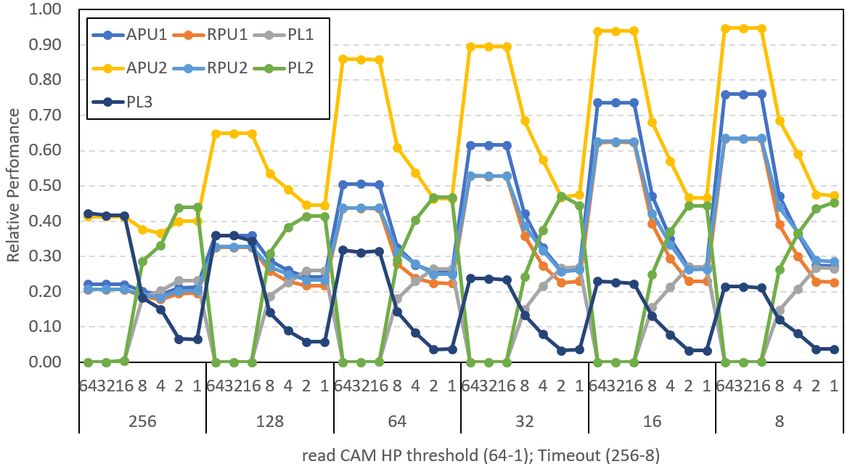
6.1 Malleability
We start assessing the malleability of the QoS mechanisms in the ZUS+ for several workloads.
Malleability measures whether the used QoS setups effectively bias the execution of those
tasks with higher priority, though this causes the other tasks to suffer more contention
interference. Without this property, the use of QoS would be ineffective. For two different
workloads Figure 9 reports the relative performance of each process with respect to the
scenario in which its SWP runs in isolation. A relative performance of X% means a slowdown
of (100/X), e.g. 50% relative performance means 2x slowdown. In particular, Figure 9 shows
the impact of changing the timeout for video requests (VPR/VPW) when both SWP1 and
SWP2 are mapped to the video traffic class, while SWP3 is mapped to the low-priority
class. As we decrease the timeout of all video ports from 1024 by half until reaching 2, the
performance of SWP1/SWP2 (RPU1/APU1/PL1 and RPU2/APU2/PL2) processes increases
at a similar pace, while PL3 relative performance sharply decreases when the timeout goes
from 1024 to 256 and remains around 10% for lower VPR/VPW timeout values.
4
Matrix multiplication is the central part of machine learning libraries like YOLOv3 [56] and account for
67% of YOLO’s execution time [25].You can also read