Long-distance distributed pressure sensing based on frequency-scanned phase-sensitive optical time-domain reflectometry
←
→
Page content transcription
If your browser does not render page correctly, please read the page content below
Research Article                                       Vol. 29, No. 13 / 21 June 2021 / Optics Express 20487

Long-distance distributed pressure sensing
based on frequency-scanned phase-sensitive
optical time-domain reflectometry
L I Z HANG , 1,* Z HISHENG YANG , 1,2 Ł UKASZ S ZOSTKIEWICZ , 3,4
K RZYSZTOF M ARKIEWICZ , 3 S ERGEI M IKHAILOV, 5 T HOMAS
G EERNAERT, 5 E TIENNE R OCHAT, 6 AND L UC T HÉVENAZ 1
1 Group  for Fibre Optics, Ecole polytechnique fédérale de Lausanne (EPFL), SCI-STI-LT Station 11, 1015
Lausanne, Switzerland
2 Present address: State Key Laboratory of Information Photonics & Optical Communications, Beijing
University of Posts and Telecommunications, Beijing 100876, China
3 InPhoTech sp. z o.o. ul. Poznańska 400 05-850 Ołtarzew, Poland
4 Faculty of Physics, Warsaw University of Technology, Warsaw 00-662, Poland
5 Department of Applied Physics and Photonics, Vrije Universiteit Brussel, Brussels B- 1050, Belgium
6 Omnisens SA, 3 Riond Bosson, 1110 Morges, Switzerland
* li.zhang@epfl.ch

Abstract: In this paper, a long-distance distributed pressure sensing system based on a special
fiber and using frequency-scanned phase-sensitive optical time-domain reflectometry is proposed.
The fiber shows high pressure sensitivity (159 MHz/bar) and low loss (3 dB/km) owing to its
simple structure made of two large air holes in the cladding. The pressure response of the two
orthogonal polarization axes of the fiber is explored distinctively. Distributed pressure sensing
over a long sensing range (720 m) and high spatial resolution (5 cm) is demonstrated, resulting
in 14,400 resolved sensing points with uncertainty on pressure of 0.49 bar. Discrimination
between the temperature/strain and pressure responses is demonstrated, taking advantage of the
different pressure and temperature sensitivities of the two polarization axes. In addition, the
temperature response of the fiber is studied and the simulation results show the possibility of
scaling the temperature sensitivity by adjusting the size of the core. The sensing distance limit
due to crosstalk between the polarization axes is also discussed.

© 2021 Optical Society of America under the terms of the OSA Open Access Publishing Agreement

1.    Introduction
Distributed fiber sensing (DFS) has drawn much attention since it provides a cost effective
solution by sensing information from thousands of or even millions of locations using just
one interrogator and a single fiber, instead of deploying a complex sensor array. Great efforts
have been devoted in the past few decades to improve the sensing range, spatial resolution, the
number of spatially-resolved points, dynamic range, response bandwidth, etc [1–4]. Traditional
DFSs using standard single mode fibers (SMF) are mostly focused on temperature and axial
strain sensing. However, with proper designs of the fiber, different quantities (such as chemical
detection, radiation and humidity), indirectly inducing a temperature or strain change in the fiber,
have been explored recently [5–7]. The progresses on DFSs bring key contributions for many
applications in various domains such as structural health monitoring, security surveillance, oil,
gas and other energy industry [8–10].
   Pressure sensing is also of important significance in the domains mentioned above; moreover,
pressure monitoring of multiple locations is subject to a high demand from today’s complex
industrial facilities and systems [11]. A few distributed pressure sensing (DPS) schemes have
been proposed based on Brillouin scattering using fibers with special coatings [12–14], dynamic

#425501                                                                       https://doi.org/10.1364/OE.425501
Journal © 2021            Received 24 Mar 2021; revised 26 May 2021; accepted 7 Jun 2021; published 16 Jun 2021
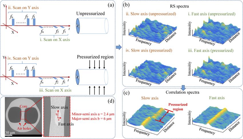
Research Article                                  Vol. 29, No. 13 / 21 June 2021 / Optics Express 20488

gratings [15,16] or optical frequency-domain reflectometry (OFDR) [17–19], demonstrating
the great potential of DPS using DFS technology. However, either the pressure sensitivity is
relatively low due to the large Young’s modulus of the fiber material silica [12–16], or the sensing
range is fundamentally limited by the sensing range of OFDR [17–19].
   In 2019, a DPS system based on phase-sensitive optical time-domain reflectometry (Φ-
OTDR) was proposed using a birefringent photonic crystal fibers (PCFs), which showed a
high pressure sensitivity at sharp spatial resolution (5 cm) [20]. However, the PCFs in [20]
show a birefringence with large fluctuations and a high loss due to the complex structure of the
fibers, which limits the sensing range to a few tens of meters. The potential to cover a larger
distance is nevertheless present, since that small spatial resolution was previously demonstrated
for temperature sensing using a single mode fiber over a sensing distance in the kilometer range
based on a similar interrogating scheme [21]. Therefore, a more specific fiber design is needed to
fulfill the requirement for practical long-distance pressure sensing, minimizing the amplitude of
birefringence fluctuations while massively reducing the propagation loss.
   In this paper, a DPS system is proposed based on Φ-OTDR with frequency scanning using
an elliptical core fiber with side air holes (SAHF) in the cladding, based on the measurement
of its birefringence change when pressure is applied. Thanks to the large air holes in the
cladding, the fiber shows a high pressure sensitivity of 159 MHz/bar. Compared with the PCF
in [20], the smartly designed SAHF shows a much simpler structure, leading to a massive loss
reduction (3 dB/km), which is essential for long distance distributed sensing, while maintaining
a comparable pressure sensitivity. As a result, pressure sensing with 5 cm spatial resolution
and 720 m sensing range is demonstrated, leading to 14,400 resolved sensing points subject to
a pressure uncertainty of 0.49 bar. The additional benefit of a low temperature sensitivity of
the birefringence (6 MHz/k) is verified experimentally, too. Incidentally, a full discrimination
between temperature/strain and pressure responses is demonstrated for the first time in distributed
fiber sensing, taking advantage of the different pressure and temperature sensitivities for the light
propagating along either of the two orthogonal polarization eigenaxes. In addition, pressure
and temperature sensitivities for different core diameters are investigated through simulation.
The results show a trade-off between the temperature sensitivity and the fiber loss, which can be
adapted by adjusting the ellipticity of the core. We also discuss the sensing distance limit due to
the crosstalk between the two polarization principal axes.

2.   Principle
The working principle of the proposed DPS is illustrated in Fig. 1: the birefringence change
of the fiber caused by the pressure change can be retrieved by comparing the frequency shift
in Rayleigh spectra of the two polarization axes, respectively. The Rayleigh scattering (RS)
spectrum of all the sensing locations along the fiber can be obtained by simply scanning the
frequency of the interrogating optical pulses. The local phase change of the fiber, induced by
environmental changes, such as temperature, strain or hereby pressure variations, can be retrieved
from the frequency shift (FS) of the corresponding RS spectrum with respect to a reference
RS spectrum [22]. For a birefringent fiber, since the refractive indices of the two polarization
principal axes are different, the RS spectra also depend on the polarization of the interrogating
pulses. By sending optical pulses with orthogonal polarizations, aligned sequentially along the
two principal polarization axes of the fiber, respectively, and then scanning the frequency of
the interrogating light pulse, the system enables to interrogate the RS spectra of the two axes
separately. Since the structure of the fiber is asymmetric, the pressure-induced phase changes
for each polarization axis are different, i.e. the birefringence change can be evaluated from the
difference in the FSs of each axis.
   In 1986, optical fibers known as side air-hole fibers (SAHF) were specifically designed to
achieve pressure sensing [23]. The two large air holes in their cladding bring a strong asymmetry
Research Article                                      Vol. 29, No. 13 / 21 June 2021 / Optics Express 20489

       Fig. 1. Pressure sensing principle: (a) frequency scanning sequence for the interrogating
       pulses of the reference and live measurements; (b) corresponding coherent Rayleigh
       scattering (RS) spectral and distance map; (c) correlation spectra between reference and live
       measurements for each polarization axis; (d) SEM image of the sensing fiber cross section

in the fiber cross-section, with the direct purpose that a variation of the external pressure will
induce changes in the fiber birefringence. The sensitivity of SAHF to pressure is high since the
volume occupied by the air holes as well as the asymmetry of the fiber cross section is large [24].
The fiber structure resembles the PM "panda" fiber, except that the fiber core is here surrounded
by two large air holes instead of stress-applying rods in "panda" fibers. The two remarkable
features of this SAHF fiber are the simplicity of its structure and its core dimension similar to
SMFs. These features translate into a low propagation loss together with a reasonable splicing
loss, making SAHFs promising candidates for long distance distributed fiber sensing. The fiber
we used here is a specially designed fiber manufactured by InPhoTech, showing an elliptical
core and two large air side holes in the cladding. Its cross-section is shown in Fig. 1(d), with
lengths of the minor and major semi-axes of 2.4 µm and 6 µm, respectively. It maintains the key
features of SAHFs of a low propagation loss (3 dB/km) and a low splicing loss (less than 1 dB).
In addition, the elliptical core increases the birefringence of the fiber, significantly alleviating any
polarization cross talk. However, the temperature sensitivity turns out to be slightly increased,
too, and this will be explained more in details in the discussion section.
   Owing to the large air holes in the cladding of the SAHF, the stress induced by the pressure
loading on the fiber concentrates more on the Y axis (slow axis), resulting in a significant
enhancement of the pressure sensitivity on this axis, while the pressure sensitivity on the X axis
(fast axis) is kept similar to that of a plain solid SMF. Therefore, the optical path change on
the Y axis (or slow axis) will be much larger than on the X axis (or fast axis) under the same
pressure change condition, resulting in a large frequency shift for the Y axis while the other axis
experiences a minor effect, as shown in Fig. 1(c).

3.   Experimental setup
The experimental setup is sketched in Fig. 2, where the interrogator is the same as in [20,25]. The
light source consists of a distributed feedback laser (DFB) with a linewidth of 1 MHz, followed
by an intensity modulator (two cascaded electro-optic modulators) and an erbium-doped fiber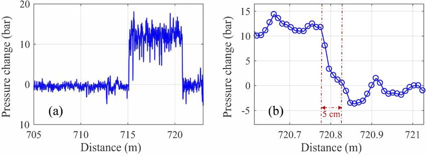
Research Article                                Vol. 29, No. 13 / 21 June 2021 / Optics Express 20490

optical amplifier (EDFA) to shape optical pulses with high enough extinction ratio and short
pulse duration. The optical pulses are then sent to a polarization switch and controller, so that
their polarization states can be alternatively aligned along each polarization eigenaxis of the fiber
under test. The frequency shift (FS) induced by a temperature change δT or a pressure change
δP can be evaluated separately along each axis by performing a cross correlation on their RS
spectra separately.

                                    Fig. 2. Experimental setup.

   Fast and broad (50 GHz) frequency scans of the interrogating pulses are achieved by direct
tuning of the laser current with a frequency scanning step of 81 MHz, where the laser has been
calibrated before the measurement using an optical spectral analyzer with a high resolution
of 4 MHz, so that the dependence of the laser frequency on the injected current is precisely
determined. The laser is classically temperature-controlled by a dedicated driver, so that the
frequency shift drift can be ignored over a relatively short time. A segment of about 5 m long
near the fiber end is placed into a hydro-static oil pressure chamber monitored by a pressure
meter based on an electric transducer. The SAHF under test shows a birefringence of ∼ 5 × 10⁻⁵
in term of refractive index. The length of the fiber under test is ∼720 m.

4.     Experimental results
4.1.    Pressure and temperature sensitivities
A first test has been carried out when the fiber is interrogated using a 2 ns pulse, corresponding
to a spatial resolution of 20 cm. The pressure-induced frequency shifts for the two orthogonal
polarizations are measured from 0 to 18 bar and results are shown in Fig. 3(a). The sensitivities for
the two axes are calculated to be 148.6 MHz/bar and -10.4 MHz/bar, respectively. A discrepancy
can be observed between these numbers and those published in [25], though they concern the
same fiber (Fiber H in [25] ). However, the pressure test bench we used before was a gas chamber
that only sustains a maximum pressure of 2 bar. Only 4 distinct pressure values could be applied
over this much restricted range. Besides, the chamber experienced substantial temperature
changes when varying the chamber pressure as a result of the gas compression-decompression
processes. In the experiment reported here, a pressurizing liquid (oil) is used. It can sustain much
higher pressures and the temperature tends to be constant during the pressure change process.
Altogether this significantly increases the reliability of the result presented here.
   We also tested the temperature sensitivity of the birefringence by placing a section of the
SAHF into a thermal water bath and monitoring the water temperature precisely with a Platinum
resistance thermometer. From the results shown in Fig. 3(b) we can see that the thermal responses
on both axes are nearly the same, confirming the results obtained in side hole fibers with Bragg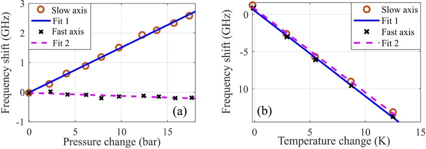
Research Article Vol. 29, No. 13 / 21 June 2021 / Optics Express 20491
Fig. 3. (a) Pressure and (b) temperature responses of the two polarization principal axes of
the fiber.
gratings (FBG) imprinted in the fiber core [26]. The temperature sensitivities are -1.121 GHz/K
and -1.116 GHz/K for the fast axis and slow axis, respectively.
The birefringence response to temperature, calculated from the experimental results, is
6 MHz/K, which is much smaller compared to the expected changes of pressure in field
conditions, since 1 K change gives an equivalent shift to that caused by a pressure change of
0.04 bar, considering the pressure response of 159 MHz/bar. This comes from a birefringence
dependence on temperature mainly due to a differential thermal expansion between cladding
and core of the fiber for fast and slow axes, which remains limited with this fiber design. The
pure temperature dependence of the refractive index (thermo-optical effect) can be reasonably
considered as identical for the 2 axes.
4.2. Long-distance distributed pressure sensing with high spatial resolution
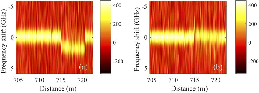
After the characterizations of the fiber sensitivities, we reduced the pulse width to 500 ps (i.e.5 cm
spatial resolution) to bring the system to its ultimate performance. The pressure responses of the
correlation spectra of both polarization axes under a pressure change of 12 bar are illustrated
in Fig. 4, from which we can see a clear frequency shift for the slow axis (in Fig. 4(a)) but no
marked frequency shift for the fast axis in Fig. 4(b). In Fig. 5, the pressure change distribution
along the fiber is calculated through the pressure sensitivity obtained in the previous section.
The results matches well with the applied pressure (12 bar) and the high spatial resolution is
confirmed from the step transition shown on the magnified section in Fig. 5(b).
Fig. 4. Correlations of RS spectra when a 12 bar pressure is applied. (a) slow axis; (b) fast
axis (5 cm spatial resolution). Only a section containing the pressure chamber and some
spare pressure-free lengths is represented, located near the fiber far end.
The calculated pressure uncertainty is estimated to be 0.49 bar, by dividing the measured
frequency uncertainty ∆F by the measured pressure sensitivity SP , i.e. ∆P = ∆F/SP , where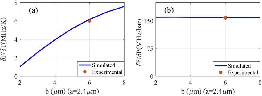
Research Article Vol. 29, No. 13 / 21 June 2021 / Optics Express 20492
Fig. 5. (a) Pressure change distribution along the final section of the fiber where pressure
is applied; (b) Magnified view around the position of a pressure step transition (chamber
outlet), demonstrating the 5 cm spatial resolution.
∆F is the estimated standard deviation over the first 100 points of the measured frequency shift.
Ideally the pressure experienced by the fiber in the chamber should be uniform, provided that the
fiber is fully surrounded by the liquid. However, in some locations, the fiber may be touching
the pipe wall, so that the pressure is here not isotropic any more. This might be the reason why
the measured pressure in the chamber shows larger fluctuations. The fiber before the pressure
chamber has been placed into a water bath to be isolated from environmental fluctuations, while
the small portion after the chamber could not be. This simply explains why the fluctuations after
the pipe are also more pronounced.
It should be noted that the pressure change applied to the fiber does not exceed 15 bar, as a
result of spurious leaks around fiber by-passes at high pressure. Actually, the measurable range is
only limited by the reference frequency range of the laser scan. Since the hydrostatic pressure
measurement does not require a fast measurement, the scan can be achieved by tuning the laser
temperature, and normally this can enable a scanning range of some 200 GHz for a DFB laser.
As reported in [21], a temperature range larger than 100 ◦ C can be measured using a very similar
system, which translates into an equivalent pressure change of some 1000 bar.
4.3. Pressure and temperature discrimination
In Fig. 3, the measured frequency shifts on both polarization axes are represented when temperature
and pressure changes are distinctively applied, indicating a clear potential to discriminate the
two quantities. While the frequency shifts due to temperature are basically identical for the
2 birefringence axes, they are clearly distinct in the case of pressure, so that it leads to a
well-conditioned set of 2 equations connecting frequency shifts from the 2 axes and the 2
quantities under question. Similar to the approach in [27], the frequency shifts of the system can
be described as follows:
⎢ δFfast ⎥ ⎢ST,fast ST,slow ⎥ ⎢δT ⎥
⎡ ⎤ ⎡ ⎤ ⎡ ⎤
⎢ ⎥=⎢ ⎥×⎢ ⎥ (1)
⎢δFslow ⎥ ⎢SP,fast SP,slow ⎥ ⎢δP⎥
⎢ ⎥ ⎢ ⎥ ⎢ ⎥
⎣ ⎦ ⎣ ⎦ ⎣ ⎦
where δT, δP and δF are the temperature change, pressure change and the frequency shift of the
system, respectively. The subscript of δF designates the polarization axis. Si,j is the sensitivity
where i represents the temperature (T) and pressure (P) and j represents the polarization axis.
The obtained experimental values for these sensitivities are given in section 4.1.
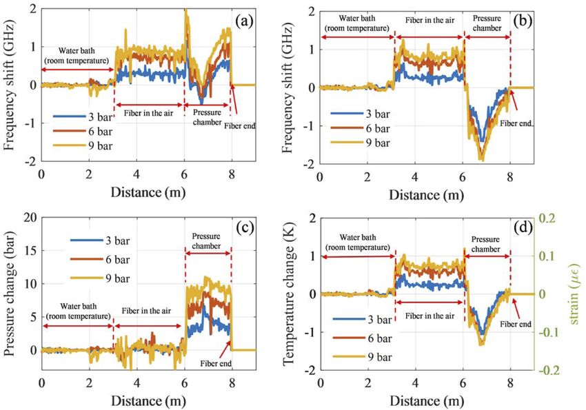
A demonstration of the discrimination between pressure and temperature/strain has been
carried out and the results are shown in Fig. 6. The length of the fiber under test is 8 m and the
first 3 m is placed into a water bath to keep the temperature constant, and the last 2 m (6-8 m)
fiber is inserted into the pressure chamber to be subject to pressure changes. There is 3 m ofResearch Article Vol. 29, No. 13 / 21 June 2021 / Optics Express 20493
fiber in-between exposed to air and subject to the changes of the ambient temperature. Different
pressure changes (3 bar, 6 bar and 9 bar) are applied to the fiber and the frequency shift responses
on both polarization axes are depicted in Fig. 6(a) and (b). It can be observed that frequency
shifts take place not only in the pressure chamber, but also over the air-exposed segment. By
inverting the well-conditioned matrix in Eq. (1), both the pressure and temperature changes can
be extracted, which are represented in Fig. 6(c) and (d). The retrieved pressure changes match the
actual applied pressures and it can be observed that there is a raise of the ambient temperature
while the experiment was carried out, as monitored by the segment exposed to air between the
water bath and the pressure chamber. From the experimental data, the accuracy on temperature
and pressure is calculated to be 0.014 ◦ C and 0.15 bar, respectively, using the estimated standard
deviation over the first 100 points. The pressure accuracy is better than the 0.49 bar in Section 4.2
because the fiber is here much shorter.
Fig. 6. Responses of (a) fast and (b) slow axis when 3 bar,6 bar and 9 bar pressure changes
are applied to the fiber. From these responses and after inverting Eq. (1) the following
distributions for physical quantities are obtained: (c) pressure and (d) temperature/strain
It should be noted that the pressure fluctuations in Fig. 6(c) can be divided into 2 categories: the
first type of fluctuations is due to the anisotropic pressure experienced by the fiber, as addressed
in the previous sub-section. It is an implementation problem of the pressure test bench rather than
an issue related to the interrogator or the sensing fiber, which can be avoided with an upgraded
pressure test bench. A second type of fluctuations, which is more fundamental, results from the
nonuniform strain and temperature applied on the fiber. As shown in Fig. 6(d), the strain along
the fiber in the chamber is not uniform, and the pressure fluctuations in Fig. 6(c) are obviously
correlated with the strain profiles. Although the strain and temperature can be discriminated
from the pressure change, they still induce correlated errors and uncertainties in the pressure
determination. For instance the traces variations in the pressure chamber in Fig. 6(d) are believed
to result from an applied strain caused by a length expansion of the chamber pipe when pressure
is applied. The strain profile along the pipe clearly supports this possible explanation.Research Article Vol. 29, No. 13 / 21 June 2021 / Optics Express 20494
5. Discussions
5.1. Temperature and pressure cross-sensitivity
An important issue for DPS remains the cross-sensitivity between temperature/axial strain
and pressure (transverse strain). Although the experimental results show that the temperature
sensitivity of the fiber is fairly reduced when compared to its pressure sensitivity, it may be worth
investigating if the temperature sensitivity can be further reduced.
The main contributions to the optical path change induced by temperature along the fiber are:
first, the difference between the thermal expansion coefficients in the cladding and the core of the
fiber; second, the temperature-induced change in the refractive index of the fiber [28]. The tested
SAHF contains two air holes in the cladding, impacting the birefringence through a differential
thermal expansion; in addition, the elliptical core shape of the fiber impacts the temperature
dependence of birefringence, too, through a thermally-induced differential change on the effective
refractive index of the two polarization modes. These 2 effects may induce opposite changes
under given conditions. It means that, with a proper design on the fiber structure, the temperature
sensitivity of birefringence can be reduced and in principle even completely canceled out.
As for the dependency of the pressure sensitivity on the fiber geometry, it has been demonstrated
that the pressure sensitivity is linearly proportional to γ 2 , where γ is the angle between the line
connecting the core and air hole centers and the tangent to the air hole passing by the fiber center,
as shown in Fig. 7 (the air holes are assumed to be circular for simplicity) [24]. As a consequence,
the variation of the core ellipticity has in principle no impact on the pressure sensitivity, under
the condition that the core is much more smaller than the air holes.
Fig. 7. The pressure sensitivity depends quadratically on the angle γ
To verify this concept, we performed simulations using Comsol, by varying the length of the
major semi-axis b of the elliptical core, to predict the pressure and temperature sensitivities of the
fiber birefringence. The simulation results are shown in Fig. 8 as blue lines and the experimental
values from our only tested fiber are represented as orange dots.
As illustrated in Fig. 8(a), on one hand the temperature sensitivity drops significantly, as b
decreases or even turns shorter than the minor semi-axis a, to reach a value of 1.05 MHz/K when
b = 2 µm). This is 5 times smaller than for the tested SAHF. This definitely suggests that an
orientation of the core ellipse orthogonal to the situation of the tested SAHF (see Fig. 1) will lead
to a significant decrease or even a vanishing of the temperature dependence of the birefringence.
In this case the longer axis of the ellipse will be oriented perpendicular to the narrow glass wall
between the air holes and this orientation may cause challenging fabrication issues.
On the other hand, the pressure sensitivity doesn’t change much with the decrease of b. The
experimental values of the fiber we used are shown in the figure, showing a good agreement with
the simulations. It must be mentioned that zero temperature sensitivity is not specific to this type
of fibers and can be obtained in birefringent photonic crystal fibers [29].
Nevertheless there exists a trade-off between the temperature sensitivity and the fiber loss. As
the core area turns smaller, the optical field will be less confined in the core and the loss due toResearch Article Vol. 29, No. 13 / 21 June 2021 / Optics Express 20495
Fig. 8. (a) Temperature and (b) pressure sensitivities with different core ellipticities (a, b:
semi-axis length). δF is obtained by subtracting the responses from the slow axis to the fast
axis, which describes the birefringence change of the fiber. Parameters used for simulation:
72 GPa, 0.17, 1.14×10⁻⁶ [1/K], and 5.5 × 10⁻⁷ [1/K] for Young’s modulus, Poisson ratio
and thermal expansion coefficient for core and cladding, respectively.
surface scattering on the air hole interface will increase and therefore limit the sensing range.
The essential merit of SAHF is to offer an excellent combination of a high response to pressure
and a moderately low temperature sensitivity with a small loss, which is essential for long range
distributed pressure sensing.
5.2. Polarization crosstalk
Since the pressure sensitivities on the two polarization axes are different, the accumulated
crosstalk between polarizations contaminates and distorts the coherent Rayleigh response when a
pressure change is applied to the fiber, hence limiting the sensing distance range of the system. It
is therefore essential to address the polarization crosstalk in the context of this study.
The polarization mode-coupling is due to waveguide fluctuations and anisotropic Rayleigh
scattering [30], and the strength of the polarization coupling can be characterized by the
mode-coupling parameter:
Γ⟩ 2 l
2⟨ˆ︁
h(β) = (2)
[1 + (∆βl)2 ]
where ∆β = | βx − βy | and βx , βy are the propagation constants for the two principle polarization
axes. l is the correlation length of the fluctuations and ˆ︁ Γ is an auxiliary constant to allow
expressing the local coupling coefficient as Γxy (z) = ˆ︁
Γf (z), where f (z) represents the fluctuation
of the waveguide parameters.
For highly birefringent fibers, only the polarization coupling due to waveguide fluctuations is
taken into consideration, since its correlation length (in the order of 10−2 m) is much larger than
that of Rayleigh scattering (much shorter than 10−6 m). From the knowledge obtained by studying
Panda fibers, the mode coupling mainly originates from the deformations of stress-applying parts
[31]. By similarity, we here assume that the deformations of the side holes is the main origin for
mode coupling, justified by the structural resemblance of the 2 types of fiber. Then we use the
approximation [31]:
2
Γ = − k(C1 − C2 )(0.108 − ∆)ˆ︁
ˆ︁ θ d (m−1 ) (3)
7
where k is the wavenumber in vacuum, C1 and C2 denote the stress-optical coefficients and
C1 − C2 = 3.36 × 10⁻⁵ mm2 /kg, ∆ is the relative difference in refractive index between core and
θ d (in unit of degree) denotes the rms deviation of the angle fluctuations in the side
cladding and ˆ︁
air holes.Research Article Vol. 29, No. 13 / 21 June 2021 / Optics Express 20496
As a rough estimation, we assume that l = 0.01 m, ˆ︁ θ d = 0.2◦ , fiber length L=1 km and ∆ =0.4
−5
percent. The birefringence of our fiber is 5×10 at a wavelength of 1550 nm, so that the calculated
Γ)2 = 0.66 m−2 , h = 6.4 × 10⁻⁵ m−1 and the crosstalk CT≡ 10 log PPxy = 10 log(2hL) = −9 dB
(ˆ︁
(the factor 2 comes from the round-trip of the signal along the fiber). This value indicates that
the polarisation crosstalk remains tolerable over 1 km (less than 13% signal contamination by
the orthogonal polarisation), but may turn critical over longer distances, in agreement with
observations in classical polarisation-maintaining fibers showing similar birefringences.
It should be noted that the waveguide deformations are factors intrinsic to the sole fiber
structure, setting a lower bound for the mode coupling. Extrinsic factors such as microbendings
in real situations will also impact on the crosstalk, but integrating this aspect is beyond the scope
of this study at this stage.
6. Conclusion
In summary, we propose a distributed pressure sensing based on Φ-OTDR and a special fiber
with elliptical core and 2 side air holes in the cladding. Thanks to the large air holes in the
fiber, its birefringence is very sensitive to pressure changes, which translates into a frequency
compensation of 159 MHz/bar, while the temperature sensitivity is kept at only 6 MHz/K. It is
quite remarkable that this simple fiber structure can lead to such good responses, fully comparable
with much more sophisticated photonic crystal designs, offering a very affordable solution to the
lingering problem of distributed pressure sensing.
Owing to the high sensitivity of Φ-OTDR, associated to the low transmission and splicing
losses to standard fibers observed with this SAHF, long distance (∼720 m) distributed pressure
sensing is demonstrated with high spatial resolution (5 cm). The potential to further reduce the
temperature sensitivity is discussed, which is verified through simulation and can be realized
by changing the size and orientation of the core ellipse. The crosstalk between polarizations is
discussed which can provide an estimation of the sensing length limitation of a given fiber.
Funding. TEAMTECH programme of the Foundation for Polish Science co-financed by the European Union under
the European Regional Development Fund (NODUS); H2020 Marie Skłodowska-Curie Actions (FINESSE 722509).
Acknowledgments. The authors thank Dr. Jiangtao Zhou from EPFL for the kind help to obtain the SEM image
of the fiber.
Disclosures. The authors declare no conflicts of interest.
Data availability. Data underlying the results presented in this paper are not publicly available at this time but may
be obtained from the authors upon reasonable request.
References
1. Y. Fu, R. Zhu, B. Han, H. Wu, Y.-J. Rao, C. Lu, and Z. Wang, “175-km Repeaterless BOTDA With Hybrid High-Order
Random Fiber Laser Amplification,” J. Lightwave Technol. 37(18), 4680–4686 (2019).
2. A. Dominguez-Lopez, M. A. Soto, S. Martin-Lopez, L. Thévenaz, and M. González-Herráez, “Resolving 1 million
sensing points in an optimized differential time-domain Brillouin sensor,” Opt. Lett. 42(10), 1903–1906 (2017).
3. D. Chen, Q. Liu, X. Fan, and Z. He, “Distributed Fiber-Optic Acoustic Sensor With Enhanced Response Bandwidth
and High Signal-to-Noise Ratio,” J. Lightwave Technol. 35(10), 2037–2043 (2017).
4. L. Costa, H. F. Martins, S. Martín-López, √ M. R. Fernández-Ruiz, and M. González-Herráez, “Fully distributed
optical fiber strain sensor with 10−12 ε/ hz sensitivity,” J. Lightwave Technol. 37(18), 4487–4495 (2019).
5. X. Lu, P. J. Thomas, and J. O. Hellevang, “A Review of Methods for Fibre-Optic Distributed Chemical Sensing,”
Sensors 19(13), 2876 (2019).
6. R. Magalhães, A. Garcia-Ruiz, H. F. Martins, J. Pereira, W. Margulis, S. Martin-Lopez, and M. Gonzalez-Herraez,
“Fiber-based distributed bolometry,” Opt. Express 27(4), 4317–4328 (2019).
7. S. Liehr, M. Breithaupt, and K. Krebber, “Distributed Humidity Sensing in PMMA Optical Fibers at 500 nm and 650
nm Wavelengths,” Sensors 17(4), 738 (2017).
8. X. Bao and L. Chen, “Recent Progress in Distributed Fiber Optic Sensors,” Sensors 12(7), 8601–8639 (2012).
9. A. Barrias, J. R. Casas, and S. Villalba, “A Review of Distributed Optical Fiber Sensors for Civil Engineering
Applications,” Sensors 16(5), 748 (2016).
10. A. Masoudi and T. P. Newson, “Contributed review: Distributed optical fibre dynamic strain sensing,” Rev. Sci.
Instrum. 87(1), 011501 (2016).Research Article Vol. 29, No. 13 / 21 June 2021 / Optics Express 20497
11. L. Schenato, A. Galtarossa, A. Pasuto, and L. Palmieri, “Distributed optical fiber pressure sensors,” Opt. Fiber
Technol. 58, 102239 (2020).
12. A. Méndez and E. Diatzikis, “Fiber optic distributed pressure sensor based on brillouin scattering,” in Optical Fiber
Sensors, (Optical Society of America, 2006), p. ThE46.
13. G. Zhang, H. Gu, H. Dong, L. Li, and J. He, “Pressure sensitization of brillouin frequency shift in optical fibers with
double-layer polymer coatings,” IEEE Sens. J. 13(6), 2437–2441 (2013).
14. Y. Dong, L. Qiu, Y. Lu, L. Teng, B. Wang, and Z. Zhu, “Sensitivity-enhanced distributed hydrostatic pressure sensor
based on botda in single-mode fiber with double-layer polymer coatings,” J. Lightwave Technol. 38(8), 2564–2571
(2020).
15. Y. H. Kim, H. Kwon, J. Kim, and K. Y. Song, “Distributed measurement of hydrostatic pressure based on Brillouin
dynamic grating in polarization maintaining fibers,” Opt. Express 24(19), 21399–21406 (2016).
16. L. Teng, H. Zhang, Y. Dong, D. Zhou, T. Jiang, W. Gao, Z. Lu, L. Chen, and X. Bao, “Temperature-compensated
distributed hydrostatic pressure sensor with a thin-diameter polarization-maintaining photonic crystal fiber based on
Brillouin dynamic gratings,” Opt. Lett. 41(18), 4413–4416 (2016).
17. T. Chen, Q. Wang, R. Chen, B. Zhang, C. Jewart, K. P. Chen, M. Maklad, and P. R. Swinehart, “Distributed
high-temperature pressure sensing using air-hole microstructural fibers,” Opt. Lett. 37(6), 1064–1066 (2012).
18. R. M. Gerosa, J. H. Osório, D. Lopez-Cortes, C. M. Cordeiro, and C. J. De Matos, “Distributed pressure sensing
using an embedded-core capillary fiber and optical frequency domain reflectometry,” IEEE Sens. J. 21(1), 360–365
(2021).
19. L. Schenato, A. Pasuto, A. Galtarossa, and L. Palmieri, “An optical fiber distributed pressure sensing cable with
pa-sensitivity and enhanced spatial resolution,” IEEE Sens. J. 20(11), 5900–5908 (2020).
20. S. Mikhailov, L. Zhang, T. Geernaert, F. Berghmans, and L. Thévenaz, “Distributed Hydrostatic Pressure Measurement
Using Phase-OTDR in a Highly Birefringent Photonic Crystal Fiber,” J. Lightwave Technol. 37(18), 4496–4500
(2019).
21. L. Zhang, L. D. Costa, Z. Yang, M. A. Soto, M. González-Herráez, and L. Thévenaz, “Analysis and Reduction of
Large Errors in Rayleigh-Based Distributed Sensor,” J. Lightwave Technol. 37(18), 4710–4719 (2019).
22. Y. Koyamada, M. Imahama, K. Kubota, and K. Hogari, “Fiber-Optic Distributed Strain and Temperature Sensing
With Very High Measurand Resolution Over Long Range Using Coherent OTDR,” J. Lightwave Technol. 27(9),
1142–1146 (2009).
23. H. M. Xie, K. Okamoto, P. Dabkiewicz, and R. Ulrich, “Side-hole fiber for fiber-optic pressure sensing,” Opt. Lett.
11(5), 333 (1986).
24. J. Clowes, S. Syngellakis, and M. Zervas, “Pressure sensitivity of side-hole optical fiber sensors,” IEEE Photonics
Technol. Lett. 10(6), 857–859 (1998).
25. L. Zhang, Z. Yang, Ł. Szostkiewicz, K. Markiewicz, T. Nasilowski, and L. Thévenaz, “Fully distributed pressure
sensing with ultra-high-sensitivity using side-hole fibers,” in Optical Fiber Sensors, (Optical Society of America,
2018), p. WF13.
26. E. Chmielewska, W. Urbańczyk, and W. J. Bock, “Measurement of pressure and temperature sensitivities of a Bragg
grating imprinted in a highly birefringent side-hole fiber,” Appl. Opt. 42(31), 6284 (2003).
27. X. Lu, M. A. Soto, and L. Thévenaz, “Temperature-strain discrimination in distributed optical fiber sensing using
phase-sensitive optical time-domain reflectometry,” Opt. Express 25(14), 16059–16071 (2017).
28. G. B. Hocker, “Fiber-optic sensing of pressure and temperature,” Appl. Opt. 18(9), 1445–1448 (1979).
29. T. Martynkien, A. Anuszkiewicz, G. Statkiewicz-Barabach, J. Olszewski, G. Golojuch, M. Szczurowski, W. Urbanczyk,
J. Wojcik, P. Mergo, M. Makara, T. Nasilowski, F. Berghmans, and H. Thienpont, “Birefringent photonic crystal
fibers with zero polarimetric sensitivity to temperature,” Appl. Phys. B 94(4), 635–640 (2009).
30. K. Takada, K. Okamoto, Y. Sasaki, and J. Noda, “Ultimate limit of polarization cross talk in birefringent polarization-
maintaining fibers,” J. Opt. Soc. Am. A 3(10), 1594–1603 (1986).
31. K. Okamoto, Y. Sasaki, and N. Shibata, “Mode coupling effects in stress-applied single polarization fibers,” IEEE J.
Quantum Electron. 18(11), 1890–1899 (1982).You can also read