Low Radio Frequency Observations from the Moon Enabled by NASA Landed Payload Missions
←
→
Page content transcription
If your browser does not render page correctly, please read the page content below
The Planetary Science Journal, 2:44 (16pp), 2021 April                                                                          https://doi.org/10.3847/PSJ/abdfc3
© 2021. The Author(s). Published by the American Astronomical Society.

Low Radio Frequency Observations from the Moon Enabled by NASA Landed Payload
                                    Missions
         Jack O. Burns1              , Robert MacDowall2                 , Stuart Bale3   , Gregg Hallinan4   , Neil Bassett1   , and Alex Hegedus5
1
    Center for Astrophysics & Space Astronomy, Department of Astrophysical and Planetary Sciences, University of Colorado Boulder, Boulder, CO 80516, USA
                                                                    jack.burns@colorado.edu
                                          2
                                            NASA Goddard Space Flight Center, Code 695, Greenbelt, MD 20771, USA
                                     3
                                       Department of Physics, University of California at Berkeley, Berkeley, CA 94720, USA
                               4
                                 Astronomy Department, MC 249-17, California Institute of Technology, Pasadena, CA 91125, USA
                        5
                          Department of Climate and Space Sciences and Engineering, University of Michigan, Ann Arbor, MI 48109, USA
                             Received 2020 August 9; revised 2021 January 16; accepted 2021 January 22; published 2021 March 8

                                                                                      Abstract
             A new era of exploration of the low radio frequency universe from the Moon will soon be underway with landed
             payload missions facilitated by NASAʼs Commercial Lunar Payload Services (CLPS) program. CLPS landers are
             scheduled to deliver two radio science experiments, Radio wave Observations at the Lunar Surface of the
             photoElectron Sheath (ROLSES) to the nearside and Lunar Surface Electromagnetics Experiment (LuSEE) to the
             farside, beginning in 2021. These instruments will be pathfinders for a 10 km diameter interferometric array,
             Farside Array for Radio Science Investigations of the Dark ages and Exoplanets (FARSIDE), composed of 128
             pairs of dipole antennas proposed to be delivered to the lunar surface later in the decade. ROLSES and LuSEE,
             operating at frequencies from ≈100 kHz to a few tens of megahertz, will investigate the plasma environment above
             the lunar surface and measure the fidelity of radio spectra on the surface. Both use electrically short, spiral-tube
             deployable antennas and radio spectrometers based upon previous flight models. ROLSES will measure the
             photoelectron sheath density to better understand the charging of the lunar surface via photoionization and impacts
             from the solar wind, charged dust, and current anthropogenic radio frequency interference. LuSEE will measure the
             local magnetic field and exo-ionospheric density, interplanetary radio bursts, Jovian and terrestrial natural radio
             emission, and the galactic synchrotron spectrum. FARSIDE, and its precursor risk-reduction six antenna-node
             array PRIME, would be the first radio interferometers on the Moon. FARSIDE would break new ground by
             imaging radio emission from coronal mass ejections (CME) beyond 2Re, monitor auroral radiation from the
             B-fields of Uranus and Neptune (not observed since Voyager), and detect radio emission from stellar CMEs and
             the magnetic fields of nearby potentially habitable exoplanets.
             Unified Astronomy Thesaurus concepts: Radio astronomy (1338); Solar radio emission (1522); Magnetospheric
             radio emissions (998); Habitable planets (695); Solar system planets (1260); Radio telescopes (1360); Space
             telescopes (1547); Lunar atmosphere (947); Lunar science (972); The Moon (1692)

                                    1. Introduction                                           RAE-2 was placed around the Moon to shield the satellite from
                                                                                              the Earthʼs surprisingly intense auroral kilometric radiation
   Even before Apollo 11ʼs first human landing on the Moon, low
                                                                                              (AKR), >40 dB brighter than the Galaxy below ∼1 MHz
radio frequency telescopes were being proposed for the lunar
                                                                                              (Alexander et al. 1975). RAE-2 carried a pair of long, 229 m,
surface. At the first Lunar International Laboratory Symposium
                                                                                              traveling-wave V-antennas. RAE-2 focused on low radio
held in Athens in 1965, a Lunar Radio Astronomy Observatory
                                                                                              frequency measurements of the Milky Way, solar and Jovian
was described that would eliminate restrictions on observations at
                                                                                              radio bursts, the AKR originating from the terrestrial magnetic
∼kilometer wavelengths (∼0.3 MHz) from the ground due to
                                                                                              field, and the extragalactic radio background.
ionospheric and human-produced radio frequency interference
                                                                                                 Renewed interest in the Moon beginning in 1984 with the
(RFI; Gorgolewski 1966). This observatory was envisioned to
                                                                                              conference on Lunar Bases and Space Activities of the 21st
have one antenna on the lunar surface and several more in lunar
                                                                                              Century brought forth new ideas for a lunar low-frequency (LF)
orbit to perform VLBI aperture synthesis. Proposed science goals
                                                                                              radio array (Douglas & Smith 1985) and a Moon–Earth baseline
included observations of the structure and spectra of extragalactic
                                                                                              radio interferometer (Burns 1985). This was followed by
sources, 21 cm H I and OH line studies, planets, and H II regions,
                                                                                              additional low radio frequency mission concepts in workshops
all observed during the lunar night, and monitoring solar activity
                                                                                              on Future Astronomical Observatories on the Moon (Burns &
during the lunar day. This concept was prescient as many of these
                                                                                              Mendell 1988), Low Frequency Astrophysics from Space (Kassim
science goals remain viable today for low radio frequency science.
                                                                                              & Weiler 1990), Science Associated with the Lunar Exploration
   The first radio astronomy observations from the Moon were
                                                                                              Architecture (NASA Advisory Council 2007), and more recently,
made by NASAʼs Radio Astronomy Explorer-2 (Explorer 49)
                                                                                              Discovering the Sky at the Longest Wavelengths with Small
satellite, which collected data in lunar orbit from 1973 to 75.
                                                                                              Satellite Constellations (Chen et al. 2019). Other published lunar
                                                                                              radio telescope mission concepts include those of Takahashi
                 Original content from this work may be used under the terms
                 of the Creative Commons Attribution 4.0 licence. Any further                 (2003), Jester & Falcke (2009), Lazio et al. (2011), Mimoun et al.
distribution of this work must maintain attribution to the author(s) and the title            (2012), Klein-Wolt et al. (2012), Zarka et al. (2012), and Bentum
of the work, journal citation and DOI.                                                        et al. (2020).

                                                                                          1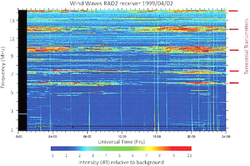
The Planetary Science Journal, 2:44 (16pp), 2021 April Burns et al.
Figure 1. Map of RFI suppression at 100 kHz based upon numerical simulations from Bassett et al. (2020). Contours indicate suppression of −10, −50, and −90 dB
relative to the incident intensity. Map colors indicate elevation. Potential landing sites are indicated by the yellow stars.
International landed payload missions have recently begun 2. The Lunar Radio Environment and Landing Sites
carrying LF radio instruments. The Chang’e-4 mission was the
The lunar farside is unique in the inner solar system. It is free
first to place a lander on the lunar farside. It housed a very LF
from human-made RFI over much of its surface. The farside
radio spectrometer and a tri-pole antenna, composed of three also protects astrophysical observations from the Earthʼs
orthogonal, electrically short, 5 m monopoles, operating powerful AKR, which occurs mostly below ≈0.5 MHz (e.g.,
between 0.1 and 40 MHz (Chen et al. 2019). Its science goals Zhao et al. 2019). In addition, system noise at 1 MHz
were to observe solar radio bursts during the lunar day and to produced by electrons in the solar wind, which induce antenna
measure the lunar ionosphere at its surface. Chang’e-4 also currents (Meyer-Vernet & Perche 1989), are reduced by the
placed a communication satellite in a halo orbit about the lunar wake cavity especially at night (e.g., Farrell et al. 1998).
Earth–Moon L2 Lagrange point, and this satellite carried the When choosing a landing site for a low radio frequency
Netherlands–China Low Frequency Explorer as a pathfinder for experiment, care should be taken that RFI and other
future lunar radio telescopes. contaminating radio emission is sufficiently attenuated to
NASAʼs Payloads and Research Investigations on the conduct the desired observations. While the farside is shielded
Surface of the Moon (PRISM) program provides transportation from human-made interference over much of its surface, it is
for science instruments to the lunar surface as part of the not perfectly radio-quiet due to the diffraction of LF waves
agencyʼs Commercial Lunar Payload Services (CLPS) initia- around the limb of the Moon. In order to estimate the RFI
tive6. It is affording new access to the near and far sides of the intensity at various locations on the farside, Bassett et al.
Moon along with the poles. Two of the early CLPS landers will (2020) numerically simulated the propagation of LF radio
ferry low radio frequency telescopes to the lunar surface to waves around the Moon. By employing a finite difference time
investigate the lunar environs and the Sun, and to prepare for domain (FDTD) algorithm, commonly used for numerical
future radio telescopes on the lunar farside. electrodynamics problems, the amount of RFI suppression,
This paper begins in Section 2 with an examination of the taking into account the electromagnetic properties of the lunar
radio environment on the Moon based upon electrodynamic material, can be calculated at any location on the farside. The
simulations and the best landing sites for radio telescopes. code functions best at low frequencies (100 kHz) where the
Then, the first NASA LF telescope experiments, Radio wave simulation resolution is comparable to the wavelength. Thus,
Observations at the Lunar Surface of the photoElectron Sheath the results of Bassett et al. (2020) can be used to evaluate the
(ROLSES) and Lunar Surface Electromagnetics Experiment suitability of a landing site based upon the frequency band of a
(LuSEE), are described in Section 3. In Section, 4 the results of given instrument.
a NASA-funded study of a Probe-class mission, Farside Array Due to the frequency-dependent nature of diffraction, the
for Radio Science Investigations of the Dark ages and level of RFI suppression will be a function of frequency.
Exoplanets (FARSIDE), to robotically emplace an interfero- Higher-frequency waves will diffract less, leading to a lower
metric array on the Moonʼs farside later in this decade will be level of RFI on the farside. In addition, the level of suppression
described; it is designed to investigate the Moon, planets, at a given frequency will vary over the surface of the farside.
exoplanets, and the early universe. A six-element precursor As one moves from the lunar limb to the antipode of the Earth
radio array, PRIME, is also described. Section 5 contains the at the center of the farside, the intensity of RFI will decrease.
summary and conclusions for this paper. This effect is shown clearly at a frequency of 100 kHz in
Figure 1. As shown in the figure, the entirety of the farside is
6
https://www.nasa.gov/content/commercial-lunar-payload-services not completely radio-quiet at 100 kHz. For example, portions
2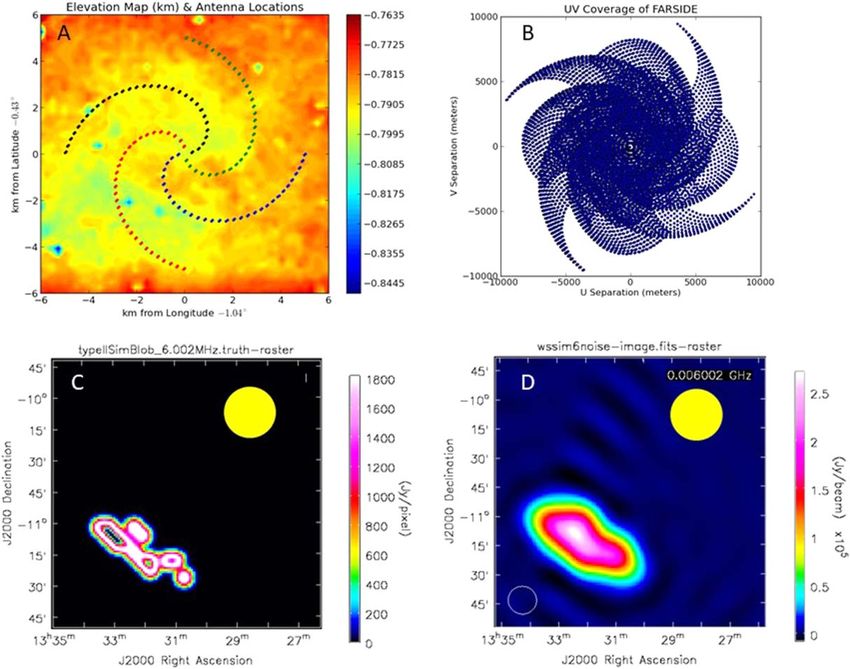
The Planetary Science Journal, 2:44 (16pp), 2021 April                                                                                       Burns et al.

of the South Pole Aitken Basin (SPAB; the large low-elevation,
purple region in the lower center portion of the map) are likely
to contain sufficient RFI to be detected by a sensitive
instrument at 100 kHz. In contrast, at higher frequencies such
as 10 MHz, the intensity of RFI is reduced by a factor of −90
dB (below which the results of numerical simulations are likely
unreliable) within a few degrees of the limb such that the entire
SPAB and nearly all of the farside are effectively free of RFI.
Thus, the best and most radio-quiet regions on the Moon upon
which to land a radio telescope that operates down to 100 kHz
is inside the 90 dB contour. The FARSIDE array described in
Section 4 will require a landing site flat to within roughly a 10
m elevation gradient over a 10 km diameter. There are
numerous such locations, with a few indicated in Figure 1.

3. Low Radio Frequency Experiments on NASAʼs Landed
                  Payload Missions
   The primary goal of both NASA landed payload radio                   Figure 2. Diagram of the NOVA-C lander that will take the ROLSES payload
science experiments, ROLSES and LuSEE, is a proof-of-                   to the lunar surface in 2021. Locations of the main electronics box and two of
concept that good, clean radio measurements can be made on              the four front-end electronics units are indicated; horizontal lines represent two
the Moon. Adherence to a strong electromagnetic compatibility           STACERs.
plan will determine whether high-fidelity spectra are possible
from the lunar surface. This includes both the instruments and          for Controlled Extension/Retraction (STACER; Bale et al.
the landers.                                                            2008) antennas and front-end electronics units. Two of the
                                                                        STACERs are mounted on NOVA-C on opposite sides of the
3.1. ROLSES—Radio Wave Observations at the Lunar Surface                lander at ∼1 m above the lunar surface, and the other two are
             of the Photoelectron Sheath                                mounted on NOVA-C close to ∼3 m above the lunar surface,
                                                                        on opposite sides of the lander and oriented at azimuths
   The LF ROLSES radio receiver system for the lunar surface            perpendicular to the ∼1 m height STACER units. Figure 2
will provide radio spectra from 10 kHz–30 MHz with ∼4 s                 shows most of these components.
resolution. ROLSES will have two frequency bands, from
10 kHz–1 MHz and 300 kHz–30 MHz. The two frequency
                                                                                               3.1.1. ROLSES Science Goals
bands will each be processed using a 512-bin real-time digital
weighted-overlap and add (WOLA) spectrometer with 512                      On the lunar dayside, photoelectrons are quasi-constantly
bins. The low-band resolution will be 1.76 kHz, and the high-           emitted from the Moonʼs surface, and this electron flux acts to
band resolution will be 58.01 kHz. Because we are limited to a          typically charge the dayside lunar surface a few volts positive.
data rate on NOVA-C of 17 kbps, the time resolution will be             In arriving at an equilibrium surface potential, the surface will
averaged spectra from two antennas for 4 s, and then averaged           charge in order to balance the two primary currents: the
spectra from the other two antennas for the next 4 s, so that the       outgoing photoelectron flux, Jp, against the incoming solar
effective time resolution is essentially 4 s. ROLSES will permit        wind electron thermal flux, Je. In nominal solar wind
determination of the electron photosheath density from ∼1 to            conditions, Jp > Je and the surface charges are positive,
∼3 m above the lunar surface. This is of scientific value and is         trapping most of the photoelectrons (Farrell et al. 2013). The
also important for determining the effect on the antenna                photoelectrons are related to surface charging, as well as the
response of larger lunar radio observatories with antennas              charging of exploration vehicles on the lunar surface. They also
laying on the lunar surface. The ROLSES data also relate to             play a role in the mobility of lunar dust particles, which
other science goals as described below. In addition, the data           consequently varies based on the solar wind conditions.
will provide continuous spectra of RFI from terrestrial                 Therefore, the best possible understanding of the photoelectron
transmitters for the 14 day mission, which is important for             sheath is important for future exploration of the lunar surface.
confirming how well a nearside lunar-surface-based radio                 There are several simulation code results published for the
observatory could observe and image solar radio bursts in the           lunar photoelectron sheath. Figure 3 shows two plots from such
frequency range of 0.01–30 MHz for the first time. This                  simulations showing the significant increase in the electron
frequency range corresponds to distances from the Sun of                density inside a height of 10 m. Note also that these two plots,
∼1 au to ∼1 solar radii, which is a very interesting spatial            which are simulations for the same interval (1998 May 1–3), do
volume for future imaging of solar radio bursts, to better              not have exactly the same results, which ROLSES is designed
understand the emission mechanisms and to enhance their                 to resolve.
space weather prediction applications.                                     The sheath will impact radio observations on the order of
   ROLSES is one of the payloads to be taken to the lunar               100 kHz and attenuate radio waves at lower frequencies. Of
surface by the NOVA-C lander of Intuitive Machines LLC7,                course, variations in the solar wind have a significant effect on
which is funded by NASA. The ROLSES payload consists of a               the photoelectron sheath, as shown in Figure 3. Assuming that
major electronics box (MEB) and four Spiral Tube & Actuator             these models are correct, then the good news is that an
                                                                        astrophysics-oriented radio observatory could make daytime
                                                                        observations down to less than 1 MHz without any impact from
7
    https://www.intuitivemachines.com/lunarlander                       the electron sheath. On the other hand, any observatory making

                                                                    3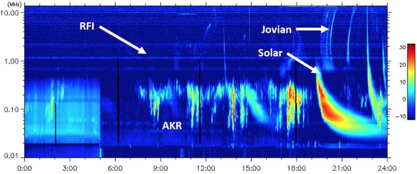
The Planetary Science Journal, 2:44 (16pp), 2021 April                                                                                        Burns et al.

                                                                                         There is no ground plane below the ROLSES antennas, so
                                                                                      some detected radio waves will likely penetrate the lunar
                                                                                      surface. They may be reflected at some depth, and ROLSES
                                                                                      may be able to detect such reflection, assuming its duration is at
                                                                                      least 4 s, providing some information about the structure below
                                                                                      the lander. Previously, the Apollo 17 lunar Surface Electrical
                                                                                      Properties instrument made such measurements at six frequen-
                                                                                      cies, with a signal generator that sent radio waves down to a
                                                                                      few kilometers into the Moon. Grimm (2018) described a
                                                                                      recent analysis of the Apollo 17 results in detail, e.g., “Because
                                                                                      no deep interfaces were detected, the thickness of the Taurus-
                                                                                      Littrow volcanic fill must exceed 1.6 km and possibly 3 km.”

                                                                                                           3.1.2. Technology Goal
                                                                                         ROLSES will provide continuous spectra of RFI from
                                                                                      terrestrial transmitters (Figure 6) for the ∼14 day mission;
                                                                                      information to confirm how well a nearside lunar surface-based
                                                                                      radio observatory could observe and image solar radio bursts in
                                                                                      the frequency range of 0.01 to ∼10 MHz for the first time. Its
                                                                                      deployed STACER lengths are 2.5 m. Its frequency range of
                                                                                      10 kHz–30 MHz is divided into two bands: 10 kHz–1 MHz and
                                                                                      300 kHz–30 MHz. The LF band resolution is ∼1.76 kHz, and
                                                                                      the high-frequency band resolution is ∼58.01 kHz. The low-
                                                                                      band sensitivity is expected to be ∼3 μV Hz−1, which will be
                                                                                      further refined after the lander and system noise are fully
                                                                                      defined.
                                                                                         Like all lunar surface payloads, the ROLSES electronics
                                                                                      need to survive the maximum lunar surface temperatures. To
                                                                                      deal with this, each of the ROLSES components has a radiator
                                                                                      plate attached to it to keep temperatures below ∼65°C. This
                                                                                      will permit it to function for the complete 14 day NOVA-C
                                                                                      mission. NOVA-C receives the data from ROLSES and sends it
                                                                                      to the ground stations. Currently the NOVA-C mission is
                                                                                      targeting landing on the Moon in Q4 of 2021. Intuitive
                                                                                      Machines has chosen the landing site to be in Oceanus
                                                                                      Procellarum near Vallis Schröteri (Schroterʼs Valley), in part
                                                                                      because there should be many smooth-surface areas there. The
Figure 3. Photoelectron density as a function of height above the lunar surface       location relative to the Earth–Moon line is 25°N, 50°W. The
is indicated in the two plots from the simulation codes by Zimmerman et al.           location is reasonable for the ROLSES payload, but not unique.
(2011) and by Poppe & Horányi (2010) for various solar wind environments.
At 1 m height for a typical solar wind, the plasma density is ∼5 × 10⁷ m−3,
and the electron plasma frequency ( fpe) is ∼64 kHz (Farrell et al. 2013).            3.2. LuSEE—The Lunar Surface Electromagnetic Experiment
                                                                                         LuSEE is a suite of sensors and electronics designed to make
lower-frequency observations, such as a heliophysics solar                            comprehensive measurements of the electromagnetic environ-
radio burst imaging observatory, would likely have refraction                         ment of the lunar surface from DC to radio frequencies
and attenuation issues for observations at less than 100 kHz due                      (∼20 MHz). LuSEE was selected by NASA in 2019 through
to the photoelectron sheath. To better understand this situation,                     the CLPS initiative. As of this writing, NASA intends to place
ROLSES will make measurements of the photoelectron sheath                             LuSEE on the lunar farside within the Schrödinger Basin
density scale height and determine the frequency at which the                         in 2024.
incoming radio waves will be attenuated/cutoff. ROLSES
measures these values based on a thermal noise spectrum,                                                  3.2.1. LuSEE Landing Site
possible wave activity at the electron plasma frequency (fpe),                          While the Schrödinger Basin (see Figure 1) is located on the
and absorption of the radio spectra of remote radio sources at                        lunar farside, it will not be completely radio-quiet near the low
frequencies at and below fpe. Figure 4 shows examples of the                          end of the LuSEE frequency band. In fact, at 100 kHz, the level
incoming radio waves that ROLSES will be detecting.                                   of suppression of radio interference will vary significantly
   Spacecraft in the interplanetary environment or orbiting planets                   across the basin. As shown in Figure 7, the level of attenuation
may be struck by dust particles, which releases electrons and ions                    varies from a factor of approximately 25 dB at the southwest
from the surface, affects the surface photoelectron environment,                      corner of the basin to near 55 dB at the northeast corner. Based
and creates signals that are detectable. ROLSES might detect dust                     on these levels of suppression, it is likely that RFI and AKR
impacting the NOVA-C lander in a similar way. The time                                will be present at a sufficient level to be detected by LuSEE.
resolution of 4 s does not permit detection of individual dust                        Specifically, the AKR from Earthʼs dayside will be observed to
particles, but could detect dust “clouds,” like those in Figure 5.                    be comparable to the flux density of the Galaxy at 100 kHz

                                                                                  4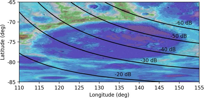
The Planetary Science Journal, 2:44 (16pp), 2021 April                                                                                                 Burns et al.

Figure 4. The WAVES instrument on the Wind spacecraft (Bougeret et al. 1995) at Sun–Earth L1 shows solar radio bursts, Earth’s auroral kilometric-wavelength
radio bursts (AKR), terrestrial ground-based transmitters (RFI), and Jovian radio emissions, during a 24 hr interval on 2012 February 20. ROLSES will be capable of
making similar observations, which would demonstrate some of the science data provided by the lunar radio array, FARSIDE, described in Section 4.

                           Figure 5. Plot showing the dust signal detected by the Cassini spacecraft when crossing the Saturn F-ring.

(∼105 Jy), whereas the AKR from Earthʼs nightside will be                               In contrast to the radio interference at lower frequencies,
∼40 dB brighter than the Galaxy in the SW quadrant of                                LuSEE high-band measurements at frequencies above 10 MHz
Schrödinger (see Figure 2 of Zarka et al. 2012).                                     will be shielded from terrestrial (artificial) shortwave emis-
   However, the presence of radio interference in the                                sions, which are attenuated by a factor of at least 90 dB over the
Schrödinger Basin provides a method with which to test                               entire basin. This lack of contamination makes the Schrödinger
predictions of the radio environment. In addition to its primary                     Basin an excellent landing site for LuSEE to make precision
science goals, LuSEE will provide a ground-truth measurement                         observations of the radio sky, as detailed in the following
with which to compare the results of the numerical simulations                       section.
of Bassett et al. (2020). Further work is underway to extend the
results of Bassett et al. (2020) to include a tenuous lunar
ionosphere and electron sheath, which will likely influence the                                              3.2.2. LuSEE Science Goals
propagation of waves at frequencies as low as 100 kHz. These                            The science targets of the LuSEE suite include lunar surface
simulations, in conjunction with LuSEE measurements, will                            plasma physics, the science of dust transport near the surface,
provide the most comprehensive study of the radio environ-                           and to serve as an LF radio pathfinder mission. The lunar
ment of the farside, and specifically the Schrödinger Basin,                          surface plasma environment is relatively poorly understood,
to date.                                                                             with a true paucity of measurements. However, any surface-

                                                                                5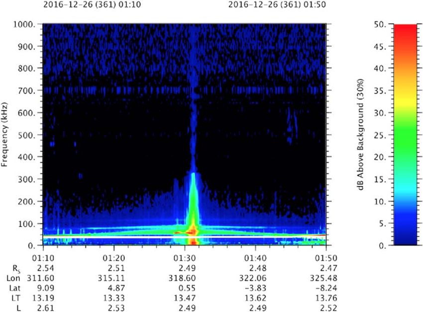
The Planetary Science Journal, 2:44 (16pp), 2021 April Burns et al.
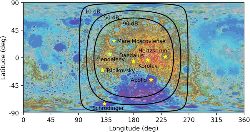
Figure 6. Dynamic spectrum shows terrestrial RFI observed by Wind/WAVES on 1999 April 2 when it passed the Moon.
Figure 7. Map of RFI suppression at 100 kHz in the Schrödinger Basin based on Bassett et al. 2020. The labels in the figure indicate the level of suppression for each
contour.
landed asset (human or robotic) must function in the surface occultation measurements have suggested rather large plasma
plasma environment. The surface electric potential that will densities 500–1000 cm−3 with scale heights of tens of
control the transport of (charged) dust should be highly kilometers, while in situ measurements suggest smaller surface
variable, depending on the upstream plasma parameters, solar plasma density. The THEMIS-ARTEMIS mission measured
UV irradiance, solar zenith angle, and local shadowing electron plasma waves, which suggested an ionospheric density
(Reasoner & Burke 1972) with predictions in the range of a of ∼0.1–0.3 cm−3 (Halekas et al. 2018). LuSEE is designed to
few volts to ∼100 V (Poppe et al. 2012; Stubbs et al. 2014). make sensitive measurements of electron plasma waves/noise
LuSEE will make true measurements of the DC electric using a technique called “quasi-thermal noise spectroscopy”
potential using a current-biased double-probe technique, which (e.g., Meyer-Vernet & Perche 1989) and can measure local
is appropriate for electric field measurements in low-density electron density and its variability, and in some cases the
plasmas (e.g., Mozer et al. 1983). The Moon is thought to electron temperature, on the lunar surface. At higher frequen-
sustain a tenuous “exo-ionosphere” supported by photoioniza- cies, up to ∼20 MHz, LuSEE will make sensitive radio
tion, electron impact ionization, and charge exchange. Radio frequency measurements of interplanetary radio bursts, Jovian
6
The Planetary Science Journal, 2:44 (16pp), 2021 April                                                                                          Burns et al.

and terrestrial natural radio emission, and the galactic
synchrotron spectrum. LuSEE will provide best-yet spectral
measurements of the quiet radio sky from the lander surface.
   The LuSEE experiment is derived from flight spare and
engineering model hardware from the NASA Parker Solar
Probe “FIELDS” instrument (hereafter PSP/FIELDS; Bale
et al. 2016), the NASA STEREO WAVES (S/WAVES;
Bougeret et al. 2008; Bale et al. 2008), the NASA Van Allen
Probes Electric Field and Waves (EFW) experiment (Wygant
et al. 2013), and the ESA Solar Orbiter Radio and Plasma
Waves (RPW) suite (Maksimovic et al. 2020).
   The LuSEE system consists of a “Main Electronics Package,”
which is comprised of three digital signal processing engines, a
low-voltage power converter, and data processing units with
interfaces to the spacecraft command and data-handling system.
These units are all flight spares, or nearly build-to-print, from the
PSP/FIELDS instrument on-orbit and have demonstrated excellent
scientific capability. The Radio Frequency Spectrometer (RFS)
subsystem is a dual channel, baseband digital radio receiver that
operates in two frequency regimes (10 kHz–2 MHz and 1.3–19.2
MHz), and is described by Pulupa et al. (2017). The RFS uses
polyphase filter techniques to reject out-of-band noise sources and
is highly configurable. Early results from the RFS on PSP (Pulupa
et al. 2020) show superb sensitivity and capability, resolving the
galactic spectrum down to a few hundred kilohertz (and a few
nanovolts). The PSP/FIELDS RFS is arguably the most capable                 Figure 8. This schematic shows the LuSEE deployable sensors: V1 and V2 are
LF radio instrument ever put into orbit, and LuSEE inherits that            6 m STACER antennas deployed to form a dipole. V3 is a STACER with a
capability. The LuSEE digital fields board (DFB) measures DC-                spherical voltage probe used to measure the vertical electric field. Fluxgate and
and AC-coupled voltage inputs from the antennas and search coil             search coil magnetometers are mounted on 2 m and 1 m carbon fiber booms,
                                                                            respectively.
magnetometer (Malaspina et al. 2016) and produces time-series
measurements to 150 k-samples/s and spectral and cross-spectral
matrices to 75 kHz. DFB is highly configurable and uses a                    the DC voltage between V3 (at 6+m above the surface) and the
                                                                            V1/V2 pair, yielding a measurement of the vertical electric field.
triggered “burst mode” to capture impulsive signals. The LuSEE
                                                                            Magnetic field measurements on LuSEE will be made from a
preamp-DFB system has capabilities to measure DC voltage
                                                                            three-axis fluxgate magnetometer (MAG), derived from PSP and
perturbations to +/- 100 V, producing direct measurements of the
                                                                            MAVEN heritage and a three-axis search coil magnetometer
lunar surface potential. The LuSEE time domain sampler (TDS) is
                                                                            (SCM) flight spare from the Radio and Plasma Waves instrument
a snapshot waveform sampler that measures five analog channels
                                                                            (Maksimovic et al. 2020) on the ESA Solar Orbiter mission. The
(and one digital) at speeds up to 2 M-samples/s and some                    MAG sensor measures magnetic fields with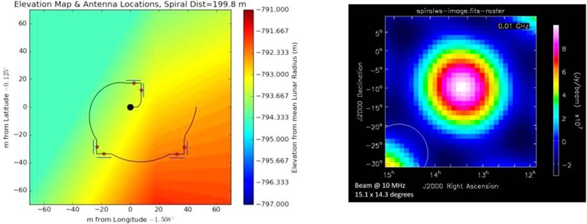
The Planetary Science Journal, 2:44 (16pp), 2021 April                                                                                                      Burns et al.

Figure 9. FARSIDE consists of three components: a commercial lander carrying the base station, four JPL Axel rovers to deploy antenna nodes, and a 128x2 (two
orthogonal polarizations) node antenna array. The array will be deployed in a spiral pattern as shown in the upper right corner. Tethers connect the base station to the
nodes, providing communications and power. NASAʼs lunar-orbiting Gateway may serve as a data relay to Earth.

consists of 128 non-cospatial orthogonal pairs of antenna/                             Here, a high-level overview of the instrument is given with a
receiver nodes distributed over a 10 km diameter in a four-arm                         few updates that extend the concept study.
spiral configuration shown in Figure 9. The nodes are deployed
in zig-zag pattern with the first antenna of the pair having a                                                   4.1.1. FARSIDE Sensitivity
vertical polarization axis (Ey) and the next having a horizontal
axis (Ex), producing measurements of all four Stokes                                      Beginning with the distinctive radio-quiet characteristics of
parameters. The FARSIDE payload mass is estimated to be                                the farside described in Section 2 as a requirement, an
1750 kg, which would be delivered to the lunar surface by a                            astronomical array at frequencies 0.1–40 MHz is driven by
commercial lander, such as Blue Originʼs Blue Moon lander9.                            sensitivity and spatial resolution. The sensitivity is determined
Four JPL Axel teleoperated rovers would deploy the nodes,                              by the number and type of antennas used in the array, and the
which are connected to the base station (lander) by science                            resolution is governed by the maximum baseline. For FAR-
tethers, providing communications, data relay, and power.                              SIDE, we use 100 m tip-to-tip thin-wire antennas. It was
   The array is planned for operations over five years with a                           determined that 128x2 dipole antennas will provide the needed
frequency range of 0.1–40 MHz. At its lowest frequency,                                sensitivity to span the science cases described in Section 4.2,
FARSIDE would operate two orders of magnitude below the                                especially probing the space plasma weather and magneto-
Earthʼs ionospheric cutoff. The array would image the sky                              spheres in exoplanetary systems. With an array diameter of 10
visible from the lunar surface once per minute to search for                           km, FARSIDE achieves a resolution of 10° FWHM at 200 kHz
radio bursts from energetic particle events within the solar                           and 10′ at 15 MHz.
system (e.g., Type II and III solar bursts; coronal mass ejection                         Sensitivity specifications for FARSIDE are summarized in
(CME)-generated planetary auroral emissions) and in exopla-                            Table 1. The array sensitivity, or minimum detectable flux
netary systems.                                                                        density, in Table 1 depends upon the frequency bandwidth, the
   A summary of the instrument and its sensitivity along with                          integration time, the system temperature, and the effective area
the overall mission design is presented next in Section 4.1. The                       of the array. The effective area is determined by the dipole
focus then turns to the solar and extrasolar system science with                       length and the antenna impedance. This was modeled using
this array in Section 4.2, including measurements of Type II/III                       NEC4.2 simulations that take into account that the dipole wires
radio bursts from the Sun, auroral radio radiation from the outer                      rest directly on the regolith. The system temperature depends
planets including the ice giants Uranus and Neptune, space                             upon the sky and regolith temperatures, and the front-end
weather and magnetospheres in exoplanetary systems, and                                amplifier. See Burns et al. (2019a) for complete details of the
probing the lunar mega-regolith layers. In Section 4.3, a six-                         modeling and simulations.
element prototype radio interferometer, PRIME, is introduced                              The FARSIDE instrument front end uses the electrically
that would reduce risks for the larger FARSIDE array.                                  short antennas to achieve sky background noise-limited
                                                                                       observations. On the lunar farside, the lunar highlands are
    4.1. Overview of the FARSIDE Instrument and Mission                                thick, have low conductivity, and vary slowly with depth, thus
                                                                                       removing the need for a ground plane. The net impact of this
                           Concept
                                                                                       multipath effect is to introduce a direction dependent comp-
   Details on the engineering design for FARSIDE are found in                          onent to the array synthesized beam. FARSIDE will use an
the NASA mission concept study report (Burns et al. 2019a).                            orbital beacon for calibration and to map both the antenna
                                                                                       beam pattern and the array synthesized beam to fully capture
9
    https://www.blueorigin.com/blue-moon/                                              this effect. The 100 m antennas are embedded within the tether

                                                                                   8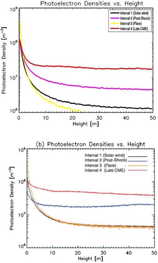
The Planetary Science Journal, 2:44 (16pp), 2021 April                                                                                     Burns et al.

                                                                          Table 1
                                                                     FARSIDE Sensitivity

                     Quantity                                                              Value
                     Frequency Coverage                                                    0.1–40 MHz (1400 × 28.5 kHz channels)
                     Antenna Efficiency                                                     6.8 × 10⁻⁶ @ 200 kHz; 9.5 × 10⁻⁵ @ 15 MHz
                     System Temperature (Tsys)                                             1 × 10⁶ K @ 200 kHz; 2.7 × 10⁴ K @ 15 MHz
                     Effective Collecting Area (Aeff)                                      ∼12.6 km2 @ 200 kHz; 2240 m2 @ 15 MHz
                     System Equivalent Flux Density (2kBTsys/Aeff)                         230 Jy @ 200 kHz; 2.8 × 10⁴ Jy @ 15 MHz
                     1σ Sensitivity for 60 s, Δν = ν/2                                     66 mJy @ 200 kHz; 933 mJy @ 15 MHz

                                                                                   10,000 square degrees of the sky every 60 s over 1400
                                                                                   frequency channels. This would then produce dynamic spectra
                                                                                   at the location of each bursting object including Type II/III
                                                                                   solar emissions and bursts in any of the several thousand
                                                                                   nearby exoplanetary system counterparts as well as CME-
                                                                                   driven auroral emissions from nearby terrestrial exoplanets.

                                                                                                   4.1.3. Synthetic FARSIDE Observations
                                                                                      Recently, Hegedus et al. (2020) utilized a combination
                                                                                   of the Common Astronomy Software Applications package
                                                                                   (McMullin et al. 2007), lunar surface maps from Lunar
Figure 10. This JPL Axle rover is shown deploying a polyimide tether similar       Reconnaissance Orbiter (LRO) Lunar Orbiter Laser Altimeter
to that proposed for FARSIDE. See Matthews & Nesnas (2012) for rover               (LOLA; Barker et al. 2016), and Spice (Acton 1996) to define a
details.                                                                           simulated array on the Moonʼs surface. This approach properly
                                                                                   aligns the reference frames from the lunar surface to the sky
and will be placed directly on the lunar surface. The array                        for the purpose of observing LF emissions. Here, the software
leverages existing designs from high heritage front-end                            pipeline has been adapted for the simulation of FARSIDE
amplifiers, fiber optics, and the correlator system based upon                       observations. The 10 km, four-armed spiral pattern of FAR-
ground-based observatories such as the Owens Valley Radio                          SIDE on top of an elevation map from LOLA data is shown
Observatory Long Wavelength Array (Anderson et al. 2018).                          in panel (A) of Figure 11. The array consists of 256 antennas,
                                                                                   128 pairs of X and Y polarizations that lie nearly side by side,
                                                                                   each of which are 100 m in length. The instantaneous u-v
                  4.1.2. Deployment and Operations
                                                                                   coverage (projected baselines) of the array for an observation at
   The concept design calls for operations during the lunar                        its zenith is shown panel (B) of Figure 11.
night as well as the lunar day using proven low-temperature                           One of the scientific targets of FARSIDE is imaging solar
electronics and batteries. Recent tests indicate that core                         Type II and III radio bursts. The simulation pipeline for
constituents such as resistors and capacitors, forming the basis                   FARSIDE has been applied to this problem, using a model-
of the electronic components of the FARSIDE receiver nodes,                        inspired Type II burst as input to the array in order to assess its
are capable and survivable down to temperatures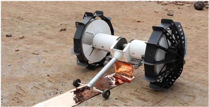
The Planetary Science Journal, 2:44 (16pp), 2021 April Burns et al.
Figure 11. (A): distribution of FARSIDE antennas on the lunar surface. Elevations derived from NASA LRO LOLA. (B): instantaneous u-v coverage for the antenna
distribution shown in panel (A). (C): estimated emission from a solar CME shock front (Type II radio burst) at 6 MHz. The yellow disk is the approximate size and
location of the Sun. (D): “cleaned” radio map of Type II burst in panel (C) as imaged via the FARSIDE array at 6 MHz with 1 minute integration. The white circle in
the lower left is the FWHM of the synthesized beam.
then slightly blurred by applying a Gaussian kernel with an bursts originate from suprathermal electrons (E > 100 eV)
FWHM of 0°. 07. The resulting “truth image” is then normalized to produced at shocks. These shocks are generally produced by
a brightness of 106 Jy and fed into the simulated FARSIDE CMEs as they expand into the heliosphere with Mach numbers
array. The simulated response of the FARSIDE antenna on the >1. Emission from a Type II burst drops slowly in frequency
lunar surface assumes Aeff/Tsys = 0.065 at 6 MHz, consistent with as the shock moves away from the Sun into lower-density
the array parameters in Table 1. Appropriate thermal noise was regions at speeds of 400–2000 km s−1. Type III bursts are
added to create a more realistic response of FARSIDE to the generated by fast (2–20 keV) electrons from magnetic
model Type II emission. These data were then imaged and reconnection, typically due to solar flares. As the fast electrons
“cleaned” (i.e., deconvolved) using the widefield imaging escape at a significant fraction of the speed of light into the
software WSClean (Offringa et al. 2014), with the resulting heliosphere along open magnetic field lines, they produce
image shown in panel (D) of Figure 11. This simulation pipeline emission that drops rapidly in frequency. As discussed in
confirms that FARSIDE would provide unprecedented imaging Section 4.2.3, FARSIDE will also attempt to detect intense type
capabilities for LF solar radio bursts, and could help explain how II and type III emissions from other stars in the solar
energetic particles are being accelerated at CME-driven shocks. neighborhood.
Acceleration at shocks. Observations of CMEs near Earth
suggest that electron acceleration generally occurs where the
4.2. Solar System and Exoplanetary Radio Science with shock normal is perpendicular to the magnetic field (Bale et al.
FARSIDE 1999), similar to acceleration at planetary bow shocks and
other astrophysical sites. This geometry may be unusual in the
4.2.1. Heliophysics
corona, where the magnetic field is largely radial. There, the
During the solar illumination of the lunar day, FARSIDE shock at the front of a CME generally has a quasi-parallel
will observe solar radio bursts, which are one of the primary geometry. Acceleration along the flanks of the CME, where the
remote signatures of electron acceleration in the inner helio- magnetic field-shock normal is quasi-perpendicular, would
sphere. FARSIDE extends the spectroscopic observations of seem to be a more likely location for the electron acceleration
LuSEE and ROLSES by producing the first radio images of and Type II emission. FARSIDE has sufficient resolution
Type II and Type III radio bursts at 2Re (Figure 11). Type II (Figure 11) to localize these acceleration site(s), yielding the
10The Planetary Science Journal, 2:44 (16pp), 2021 April Burns et al. preferred geometry of the shock normal relative to the magnetic have magnetic fields of
The Planetary Science Journal, 2:44 (16pp), 2021 April                                                                                        Burns et al.

    Figure 12. Artistʼs impression of a planet orbiting an M dwarf experiencing a CME due to a megaflare event. Credit: Chuck Carter and KISS/Caltech.

  4.2.3. The Magnetospheres and Space Weather Environments of                   solar-type star, εEridani (spectral type K2), is another priority
                      Habitable Exoplanets                                      target. For the case of M dwarfs, FARSIDE would be able to
                                                                                detect Type II bursts formed at the distance where super-
   As described above, the radio emission from the Sun and
planets provides key insights into the bulk motion of plasma in                 Alfvénic shocks should be possible for M dwarfs (Villadsen &
the solar corona and interplanetary medium and a means for                      Hallinan 2019) and directly investigate whether the observed
direct measurement of planetary magnetospheres. Extending to                    relationship observed between solar flares and CMEs (Aarnio
other stellar and planetary systems in the solar neighborhood                   et al. 2011; Osten & Wolk 2015) extends to M dwarfs. If it
will provide essential data on the impact of energetic particles                does, FARSIDE should also detect a very high rate of radio
and CMEs on planetary atmospheres and habitability, together                    bursts from this population.
with the role of planetary magnetic fields as a buffer against                      Detection of the terrestrial planet magnetospheres. All of the
such activity. The FARSIDE array, in particular, will be                        magnetized planets in our solar system, including Earth,
uniquely capable as an instrument for this science due to its                   produce bright coherent radio emission at low frequencies,
ability to extend by a factor of a hundred times lower in                       predominantly originating in high magnetic latitudes and
frequency with equivalent or better sensitivity than current or                 powered by auroral processes (Section 4.2.2; Zarka 1998).
planned ground-based arrays, enabling the routine detection of                  Detection of similar radio emission from candidate habitable
stellar CMEs, solar energetic particle events, and the magneto-                 planets is the only known method to directly detect the
spheres of extrasolar terrestrial planets for the first time                     presence and strength of their magnetospheres. The temporal
(Figure 12).                                                                    variability of this radio emission can also be used to determine
   Detection of stellar CMEs and solar energetic particles. As                  the rotation periods and orbital inclinations of these planets. As
discussed in Section 4.2.1, solar CMEs and solar energetic                      described in Section 4.2.2, the radio emission is emitted at the
particle events can be accompanied by radio bursts at low                       electron cyclotron frequency (Section 4.2.2).
frequencies, particularly Type II bursts, as well as a subset of                   Extending to the exoplanet domain requires a very large
Type III bursts (complex Type III-L bursts). The emission is                    collecting area at low frequencies, with the first detections
produced at the fundamental and first harmonic of the plasma                     likely to be ground-based. Indeed, in a recent breakthrough,
frequency and provides a diagnostic of the density and velocity                 radio emission has been detected from a possible free-floating
(a few 100 to >1000 km s−1) near the shock front, while the                     planetary-mass object (12.7 ± 1 Mjup; Kao et al. 2018). This is
flux density of the burst depends sensitively on the properties                  the first detection of its kind and confirmed a magnetic field
of the shock and solar wind (Cairns et al. 2003). Ground-based                  much higher than expected, >200 times stronger than Jupiterʼs,
radio astronomy can only trace such events to a heliocentric                    reinforcing the need for empirical data. However, the detection
distance of a few solar radii, whereas space-based radio                        of the magnetic fields of candidate habitable planets will almost
antennas can trace the propagation of shocks out to the Earth                   certainly require a space-based array if the magnetic fields are
and beyond, which is particularly relevant for characterizing                   within an order of magnitude in strength of Earthʼs magnetic
geoeffective CMEs and solar energetic particle events. The                      field. Detection of the magnetic field of planets orbiting in the
detection of equivalent interplanetary Type II and III events                   habitable zone of M dwarfs is particularly key, as such planets
from stars other than the Sun is one of the goals of the                        may require a significantly stronger magnetosphere than Earth
FARSIDE array.                                                                  to sustain an atmosphere (Lammer et al. 2007).
   FARSIDE would detect the equivalent of the brightest Type                       The detection of radio emission from planets orbiting nearby
II and Type III bursts out to 10 pc at frequencies below a few                  stars is very sensitive to the stellar wind conditions imposed by
megahertz. By imaging >10,000 deg2 every 60 s, it would                         its parent star and can serve as an indirect diagnostic of its
monitor a sample of solar-type stars simultaneously, searching                  velocity and density. It is possible to estimate the expected
for large CMEs and associated solar energetic particle events.                  radio power from such planets, based on scaling laws known to
For the αCen system, with two solar-type stars and a late M                     apply to radio emission from the solar system planets
dwarf, it would probe down to the equivalent of 10−15 W m−2                     (Zarka 2007 and references therein). These scaling relations
Hz−1 at 1 au, a luminosity at which solar radio bursts are                      are not only descriptive but predictive, with the luminosity of
frequently detected at the lowest frequencies available to                      both Uranus and Neptune predicted before the Voyager 2
FARSIDE (Krupar & Szabo 2018). The nearby young active                          encounters and found to be in excellent agreement with the

                                                                           12
The Planetary Science Journal, 2:44 (16pp), 2021 April Burns et al.
Figure 13. Left: the radio spectrum of Earthʼs AKR for 50%, 10%, and 1% of the time. The flux density across the entire detectable band can vary by factors of a few
hundred (Lamy et al. 2010). Right: the predicted average radio flux density at ∼280 kHz of known exoplanets orbiting M dwarfs from Vidotto et al. (2019) assuming a
magnetic field of 0.1 G (10% of Earthʼs magnetic field). Purple, yellow, and red data points reflect different models for the quiescent stellar wind. The horizontal gray
line represents the 5σ detection limit (y-axis on left-hand side) on the median flux density for the auroral radio emission detectable from FARSIDE in a 2500 hr
integration. The horizontal red line represents the 5 s detection limit (y-axis on right-hand side) in a 2.5 hr integration during enhanced stellar wind conditions, e.g.,
during a CME, assuming a similar degree of variability as observed for Earthʼs AKR. A large sample of planets, including some nearby candidate habitable planets
(such as Proxima b), are detectable.
measurements (Desch & Kaiser 1984). Extrapolations to terrestrial planet magnetospheres outside our solar system. The
terrestrial exoplanets in the habitable zone of M dwarfs, and radio emission can be distinguished from that of the star by
thus embedded within a dense stellar wind environment, rotational modulation, as well as circular polarization, which is
predict radio luminosities that are orders of magnitude higher largely absent for interplanetary solar radio bursts (Zarka et al.
than that of the Earth (Farrell et al. 1999; Zarka et al. 2001; 2007; Hallinan et al. 2013). Detection of magnetospheres, if
Grießmeier et al. 2007; Grießmeier 2015; Vidotto et al. 2019). present, would identify the most promising targets for follow-
During enhanced solar wind conditions, the Earthʼs radio up searches for biosignatures, as well as providing a framework
emission can increase in luminosity by orders of magnitude for comparative analysis of exoplanet magnetospheres and
(Figure 13), and a similar effect is expected for exoplanets. atmospheric composition.
Therefore, as is the case for detecting Type II bursts associated
with CMEs, it is essential to have the capability to monitor 4.2.4. Sounding of the Lunar Subsurface
large numbers of planets simultaneously to detect periods
where exoplanets greatly increase in luminosity. ROLSES will attempt to probe the subsurface layers beneath
As noted in Section 4.1, FARSIDE will image 10,000 deg2 its lander. FARSIDE has the potential to sound the mega-
of sky visible from the lunar farside every 60 s, in 1400 regolith and its transition to bedrock expected at ∼2 km below
channels spanning 100 kHz–40 MHz. The sensitivity at the the surface (Hartmann 1973). The Lunar Radar Sounder on
lower end of the band, enabled by the unique environment of board the KAGUYA (SELENE) spacecraft has provided
the lunar farside, is particularly well suited to the search for sounding observations of the lunar highlands (Ono et al.
radio exoplanets. In each FARSIDE image, there will be 2010) and found potential scatterers hundreds of meters below
the subsurface. However, the results are inconclusive due to
∼2000 stellar/planetary systems within 25 pc. At these low
surface roughness. FARSIDE, by virtue of being on the
frequencies, the spatial resolution is limited to a few degrees
surface, would not be affected by roughness. Data from a
due to scattering in the interstellar medium and interplanetary
calibration beacon in orbit could be synthesized to identify
medium. However, with one stellar system within 25 pc per ∼5
deep scatterers and the transition to bedrock at kilometer depths
square degrees, identification of the source of detected emission
by virtue of the low frequencies, which are significantly more
should be straightforward, particularly as FARSIDE is most
penetrating. Deep subsurface sounding can also be performed
likely to detect exoplanets within 10 pc (Figure 13). An
passively using Jovian bursts from 150 kHz to 20 MHz (e.g.,
advantage at these low frequencies, is that the galaxy is
Romero-Wolf et al. 2015). The array covers a 10 km × 10 km
optically thick at distancesThe Planetary Science Journal, 2:44 (16pp), 2021 April Burns et al.
Figure 14. With the distribution of three pairs of PRIME antennas in a 200 m spiral pattern on the lunar surface shown in the left panel, the resulting interferometric
“dirty” image from a “snapshot” at 10 MHz in the right panel illustrates the clear detection of a 109 Jy point source as expected for a Type II solar radio burst. The
white ellipse is the FWHM of the array beam.
transmission. Thin-wire, electrically short, 10 m antennas will the relative positions of the Earth, Moon, and Sun, and finally
be embedded within the tether, following the design concept makes dirty images of the given input distribution. This
developed for FARSIDE. Investigation of the electrical reconstructed “snapshot” image is on the right.
properties of the antennas placed directly on the dielectric
regolith will characterize the impact of the reflection of radio 5. Summary and Conclusions
waves from the subsurface. The electronics used in the antenna
After decades of study and numerous proposed concepts,
nodes will have heritage from NASAʼs heliophysics mission
radio astronomy on the Moon is finally underway. China has
SunRISE (Kasper et al. 2019), a six cubesat interferometer in
placed the first low radio frequency antenna on the lunar
high Earth orbit to measure compact structure in CMEs.
farside. This will soon be joined by NASA radio science
Finally, PRIME will test the thermal designs and baseline instruments ROLSES and LuSEE. In this paper, we presented a
concept of operations for FARSIDE. The technological roadmap for low radio frequency (∼0.1–40 MHz) observations
objective is to validate the instrument concept by demonstrat- from the Moon beginning with ROLSES and LuSEE,
ing background noise-limited performance. progressing to a six-element prototype radio interferometer
PRIME will have sufficient sensitivity to produce dynamic (PRIME), and finally a 128 × 2 antenna-node array (FAR-
spectra for transient emission from the Earth (if emplaced on SIDE) as a Probe-class mission to the lunar farside late in this
the nearside), the Sun, and Jupiter. Of particular interest are decade.
Types II and III solar bursts. If launched in the next few years, ROLSES will fly first on the Intuitive Machines CLPS lander
PRIME will observe near solar maximum, during which ∼3 in late 2021. ROLSES will deploy two dipole antennas on the
CMEs leave the Sun each day, and will detect >100 Type II/ Moonʼs nearside, at 1 m and 3 m above the lunar surface. Its
III bursts, based on well-understood power-law flux distribu- science goals include measurements of electrons and charged
tions. With Earth–Moon very long baseline Interferometry dust within a photoelectron sheath near the surface. These
(VLBI) between SunRISE and PRIME, this VLBI baseline observations will provide key data to differentiate between a
would provide very precise distance estimates via curvature of conflicting set of theoretical models. ROLSES will also
the radiation wave front for complex Type III events, which measure the temporal and spectral characteristics of the current
will resolve a long-standing controversy concerning the origin human-generated RFI from Earth to determine what solar and
of the electrons responsible for these events and their location solar system observations will be possible from the lunar
relative to the CME shock front. PRIME would also surface.
characterize LF Jovian emission with a peak flux density of LuSEE is expected to launch in Q2 of 2024 and land within
107 Jy (Carr et al. 1983), and if located on the nearside, Earthʼs the Schrödinger impact basin on the farside of the Moon. Its
AKR (Alexander et al. 1975). Characterizing these emissions suite of electromagnetic instruments will survey the lunar
will serve to refine exoplanet observations (Zarka et al. 2007) environment and determine if high dynamic range spectral and
with FARSIDE. imaging observations are possible on the farside, in preparation
Taking a point source with a flux density of 109 Jy as a for low radio frequency arrays. Like ROLSES, LuSEE will
representative test case, one can form a model PRIME beam at focus on the plasma environment, but on the farside surface.
a given frequency, done here for 10 MHz. A notional PRIME Sensitive measurements of the time-variability of the iono-
layout is seen in Figure 14 on the left—one 200 m length arm sphere will be made. In addition, dynamic spectra of radio
with three pairs of antennas placed in the zig-zag pattern for bursts from the Sun and Jupiter, and the radio-quiet sky, will be
orthogonal polarizations. The black dot represents the lander, collected to set the stage for the PRIME and FARSIDE radio
and the six red stars are the nodes for the 10 m antennas, arrays.
deployed along the tether shown by the black lines. For PRIME is a six-node array of antennas that is proposed to fly
imaging, the software pipeline described in Section 4.1.3 was on a CLPS lander to buy-down risks for the larger imaging
used along with the antenna locations and elevations shown in array FARSIDE. PRIME will focus on proving the technolo-
Figure 14. Then, the pipeline aligns reference frames and tracks gies for FARSIDE, including deployment of antennas, receiver
14The Planetary Science Journal, 2:44 (16pp), 2021 April Burns et al.
boxes, and a tether, providing power and communications, Bale, S. D., Goetz, K., Harvey, P. R., et al. 2016, SSRv, 204, 49
using a teleoperated rover. It will demonstrate the expected Bale, S. D., Reiner, M. J., Bougeret, J.-L., et al. 1999, GeoRL, 26, 1573
noise-limited performance on the lunar surface. PRIME will Bale, S. D., Ullrich, R., Goetz, K., et al. 2008, SSRv, 136, 529
Barker, M., Mazarico, E., Neumann, G., et al. 2016, Icar, 273, 346
observe Type II/III bursts from the Sun and radio emission Bassett, N., Rapetti, D., Burns, J. O., Tauscher, K., & MacDowall, R. 2020,
from Jupiter to prepare for similar FARSIDE observations of AdSpR, 66, 1265
LF radio radiation from CMEs in nearby stellar systems and Batygin, K., Adams, F. C., Brown, M. E., & Becker, J. C. 2019, PhR, 805, 1
auroral radio emission from exoplanets. FARSIDE will image Batygin, K., & Brown, M. E. 2016, AJ, 151, 22
Bentum, M. J., Verma, M. K., Rajan, R. T., et al. 2020, AdSpR, 65, 856
the sky observable from the lunar farside every minute in 1400 Bigg, E. K. 1964, Natur, 203, 1008
spectral channels to search for signatures of bursting radio Bougeret, J. L., Goetz, K., Kaiser, M. L., Bale, S. D., et al. 2008, SSRv,
emission from several thousand nearby stars and exoplanets. 136, 487
The approved PRISM CLPS missions described here, ROLSES Bougeret, J. L., Kaiser, M. L., Kellogg, P. J., et al. 1995, SSRv, 71, 231
and LuSEE, along with proposals for low radio frequency arrays, Burke, B. F., & Franklin, K. L. 1955, JGR, 60, 213
Burns, J. O. 1985, Lunar Bases and Space Activities of the 21st Century
PRIME and FARSIDE, come at a time of increasing interest in (Houston, TX: Lunar and Planetary Institute), 293
lunar exploration and the Artemis human missions to the Moon. Burns, J. O., Hallinan, G., Lux, J., et al. 2019a, Probe Study Report: FARSIDE
These signal a new paradigm for surface science and exploration (Farside Array for Radio Science Investigations of the Dark ages and
from NASA, international partners, and commercial companies. Exoplanets) (NASA), https://science.nasa.gov/science-pink/s3fs-public/
atoms/files/FARSIDE_FinalRpt-2019-Nov8.pdf
Radio astronomy projects for the Moon take advantage of new Burns, J. O., Mellinkoff, B., Spydell, M., et al. 2019b, AcAau, 154, 195
developments in transportation, communications (e.g., Lunar Burns, J. O., & Mendell, W. W. (ed.) 1988, Future Astronomical Observatories
Gateway), lunar operations, and infrastructure (e.g., Artemis). on the Moon (Houston, TX: Johnson Space Center), 569
With these initiatives taking root and blossoming in this decade, Cairns, I. H., Knock, S. A., Robinson, P. A., et al. 2003, Advances in Space
Environment Research (Dordrecht: Springer), 27
astrophysical radio telescopes on the Moon come at an opportune
Cane, H. V., Erickson, W. C., & Prestage, N. P. 2002, JGRA, 107, 1315
time with an emerging architecture to achieve high-priority Carr, T., Desch, M., & Alexander, J. 1983, in Physics of the Jovian
science objectives. With the development of new infrastructure at magnetosphere, ed. A. Dessler (Cambridge: Cambridge Univ. Press), 226
the Moon that may impact high-sensitivity, long integration Chen, X., Burns, J. O., Koopmans, L., et al. 2019, arXiv:1907.10853
observations, it is important to build these telescopes soon and to Desch, M. D., & Kaiser, M. L. 1984, Natur, 310, 755
Douglas, J. N., & Smith, H. J. 1985, in Lunar Bases and Space Activities of the
develop international agreements on RFI mitigation. 21st Century, ed. W. W. Mendell (Houston, TX: Lunar and Planetary
Institute), 301
This work is directly supported by the NASA Solar Farrell, W. M., Desch, M. D., & Zarka, P. 1999, JGR, 104, 14025
System Exploration Virtual Institute cooperative agreement Farrell, W. M., Kaiser, M. L., Steinberg, J. T., & Bale, S. D. 1998, JGR, 103,
23653
80ARC017M0006. Support was also provided by the Simons Farrell, W. M., Poppe, A. R., Zimmerman, M. I., et al. 2013, JGRE, 118, 1114
Foundation grant “Planetary Context of Habitability and Gopalswamy, M., Yashiro, S., Kaiser, M. L., Howard, R. A., & Bougeret, J.-L.
Exobiology.” We are indebted to a number of highly talented 2002, GeoRL, 29, 1265
individuals who contributed to the mission and concept studies Gopalswamy, N., Yashiro, S., Kaiser, M. L., Howard, R. A., & Bougeret, J.-L.
described in this paper. For ROLSES, this includes Damon 2001, ApJL, 548, L91
Gopalswamy, N., Yashiro, S., Krucker, G., et al. 2004, JGRA, 109, A12105
Bradley, Pietro Sparacino, William Farrell, Richard Katz, Igor Gorgolewski, S. 1966, in Proc. of the First Lunar International Laboratory
Kleyner, David McGlone, Michael Choi, Scott Murphy, and Symp. on Research in Geosciences & Astronomy, ed. F. J. Malina (Berlin:
Rick Mills at NASA/GSFC. For LuSEE, this includes Peter Springer), 78
Harvey, Keith Goetz, Lindsey Hayes, and Misty Willer. For Grießmeier, J.-M. 2015, in Characterizing Stellar and Exoplanetary
FARSIDE and PRIME, this includes Larry Teitelbaum, James Environments, Astrophysics and Space Science Library, Vol. 411 (Cham:
Springer), 213
Lux, Andres Romero-Wolf, Issa Nesnas, Patrick McGary, and Grießmeier, J. M., Zarka, P., & Spreeuw, H. 2007, A&A, 475, 359
Tzu-Ching Chang at Caltech/JPL, as well as Steve Squyres Grimm, R. E. 2018, Icar, 314, 389
and Alex Miller at Blue Origin Inc. We also thank the referees Halekas, J. S., Poppe, A. R., Harada, Y., et al. 2018, GeoRL, 45, 9450
for the thoughtful comments, which improved the manuscript. Hallinan, G., Sirothia, S. K., Antonova, A., et al. 2013, ApJ, 762, 34
Hartmann, W. K. 1973, Icar, 18, 634
Hegedus, A. M., Nénon, Q., Brunet, A., et al. 2020, RaSc, 55, e06891
ORCID iDs Izmodenov, V. V., & Alexashov, D. B. 2020, A&A, 633, L12
Jester, S., & Falcke, H. 2009, NewAR, 53, 1
Jack O. Burns https://orcid.org/0000-0002-4468-2117 Kao, M., Hallinan, G., Pineda, J. S., Stevenson, D., & Burgasser, A. 2018,
Robert MacDowall https://orcid.org/0000-0003-3112-4201 ApJS, 237, 25
Stuart Bale https://orcid.org/0000-0002-1989-3596 Kasper, J., Lazio, J., Romero-Wolf, A., et al. 2019, in IEEE Aerospace Conf.
(Piscataway, NJ: IEEE)
Gregg Hallinan https://orcid.org/0000-0002-7083-4049 Kassim, N. E., & Weiler, K. W. (ed.) 1990, in Low Frequency Astrophysics from
Neil Bassett https://orcid.org/0000-0001-7051-6385 Space, Lecture Notes in Physics, Vol. 362 (Crystal City, VA: Springer)
Alex Hegedus https://orcid.org/0000-0001-6247-6934 Klein-Wolt, M., Aminaei, A., Zarka, P., et al. 2012, P&SS, 74, 167
Kocz, J., Greenhill, L., Barsdell, B., et al. 2014, JAI, 3, 14500002
Krupar, V., & Szabo, A. 2018, in Statistical Survey of Interplanetary Type II and
References Type III Radio Bursts. USRI Proc. (Gran Canaria), 28 May–1 June 2018
Lammer, H., Lichtenegger, H. I. M., Kulikov, Y. N., et al. 2007, AsBio, 1, 185
Aarnio, A. N., Keivan, G., Stassun, W., Jeffrey, H., & Sarah, L. M. 2011, Lazio, T. J. W., MacDowall, R. J., Burns, J. O., et al. 2011, AdSpR, 48, 1942
SoPh, 268, 195 MacDowall, R. J., Lara, A., Manoharan, P. K., et al. 2003, GeoRL, 30, 8018
Acton, C. H. 1996, P&SS, 44, 65 Maksimovic, M., Bale, S. D., Chust, T., et al. 2020, A&A, 642, A12
Alexander, J. K., Kaiser, M. L., Novaco, J. C., Grena, F. R., & Weber, R. R. Malaspina, D. M., Ergun, R. E., Bolton, M., et al. 2016, JGRA, 121, 5088
1975, A&A, 40, 365 Malaspina, D. M., Szalay, J. R., Pokorný, P., et al. 2020, ApJ, 892, 115
Anderson, M. M., Hallinan, G., Eastwood, M. W., et al. 2018, ApJ, 864, 22 Manchester, W. B., IV, van der Holst, B., & Lavraud, B. 2014, PPCF, 6,
Ashtijou, M., Yang-Scharlotta, J., Hanelli, A., et al. 2020, IEEE Aerospace 064006
Conference (Piscataway, NJ: IEEE), 1 Matthews, J., & Nesnas, I. 2012, in IEEE Aerospace Conference (Piscatawy,
Bale, S. D., Goetz, K., Bonnell, J. W., et al. 2020, arXiv:2006.00776 NJ: IEEE)
15You can also read