LS2000 Admin Guide - Installation, Configuration, Operation, & Troubleshooting - Code Blue Corporation
←
→
Page content transcription
If your browser does not render page correctly, please read the page content below
LS2000
                                 Admin Guide

Installation, Configuration, Operation, & Troubleshooting

                                            800.205.7186 ● www.codeblue.com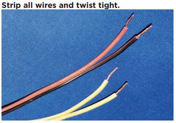
Administrator Guide
                                                                                     LS2000

                        WARNING

                        ONLY QUALIFIED PERSONNEL SHOULD INSTALL THIS UNIT. THE
                        INSTALLATION SHOULD CONFORM TO ALL LOCAL CODES. IN SOME
                        COUNTRIES, A CERTIFIED ELECTRICIAN MAY BE REQUIRED.

                        CAUTION

                        No caution is necessary for this product.

                        NOTICE TO USERS

                        Copyright © Code Blue Corporation. All rights reserved. This guide or
                        software described herein, in whole or part, shall not be reproduced,
                        translated, or reduced to any machine-readable form without prior written
                        approval from Code Blue Corporation.

                        CODE BLUE CORPORATION PROVIDES NO WARRANTY WITH
                        REGARD TO THIS GUIDE, THE SOFTWARE OR OTHER INFORMATION
                        CONTAINED HEREIN AND HEREBY EXPRESSLY DISCLAIMS ANY
                        IMPLIED WARRANTIES OF MERCHANTABILITY OR FITNESS FOR
                        ANY PARTICULAR PURPOSE WITH REGARD TO THIS GUIDE, THE
                        SOFTWARE OR SUCH OTHER INFORMATION. IN NO EVENT SHALL
                        CODE BLUE CORPORATION BE LIABLE FOR ANY INCIDENTAL,
                        CONSEQUENTIAL, OR SPECIAL DAMAGES, WHETHER BASED ON
                        TORT, CONTRACT, OR OTHERWISE, ARISING OUT OF OR IN
                        CONNECTIONS WITH THIS GUIDE, THE SOFTWARE OR OTHER
                        INFORMATION CONTAINED HEREIN OR THE USE THEREOF.

                        Code Blue Corporation reserves the right to make any modifications to this
                        guide or the information contained herein at any time without notice. The
                        software described herein may also be governed by the terms of a separate
                        user license agreement.

                        Code Blue® is a registered trademark of Code Blue Corporation.

Code Blue ● 259 Hedcor Street ● Holland, MI ● 4923 USA ● 800.205.7186 ● www.codeblue.com   Rev 6/2021   page 2 of 57   GU-165-A
Administrator Guide
                                                                                                            LS2000

                Table of Contents
                Section                                                                                                        Page

                  Introduction ...................................................................................................... 4
                  Getting Started ................................................................................................. 5
                  Power Requirements........................................................................................ 6
                  Installation Instructions ................................................................................. 11
                  How to Update Connectors ........................................................................... 15
                  Wiring Diagrams ............................................................................................. 17
                  Schematics ..................................................................................................... 18
                  Setting Up Your LS2000................................................................................. 20
                  In-Call Commands .......................................................................................... 42
                   Compatibility................................................................................................. 43
                   Configuring for Cisco Unified Call Manager .............................................. 44
                   Troubleshooting ........................................................................................... 48
                   Software Configuration................................................................................ 49
                   Remote Mount Beacon/Strobe Installation ................................................ 50
                   S-1000/S-1050/S-2000 Beacon/Strobe Installation Instructions .............. 51
                   Maintenance Schedule................................................................................. 54
                   Warranty ........................................................................................................ 56
                   Additional Download Links ......................................................................... 57

Code Blue ● 259 Hedcor Street ● Holland, MI ● 4923 USA ● 800.205.7186 ● www.codeblue.com                            Rev 6/2021            page 3 of 57   GU-165-A
Administrator Guide
                                                                                       LS2000

                  Introduction
                Thank you for choosing the Code Blue LS2000 full duplex VoIP handset device for indoor and outdoor
                applications. This telephone is part of our Emergency Signaling group of products built to meet the latest
                regulations, withstand the harshest elements and be proactive solutions for when you need them most.
                This guide provides basic and advanced configuration information for obtaining the best performance with
                the LS2000 phone.

                                     Handset Phone                          Handset w/ Volume Button

                                    Handset w/ Keypad                 Handset w/ Keypad and Volume Button

                Call Privacy Laws
                Some states require all parties to be aware that they are being recorded. Code Blue phones offer the
                ability to play a message stating that the caller is being recorded and giving the caller the option to
                continue or end the recorded call.

Code Blue ● 259 Hedcor Street ● Holland, MI ● 4923 USA ● 800.205.7186 ● www.codeblue.com     Rev 6/2021     page 4 of 57     GU-165-A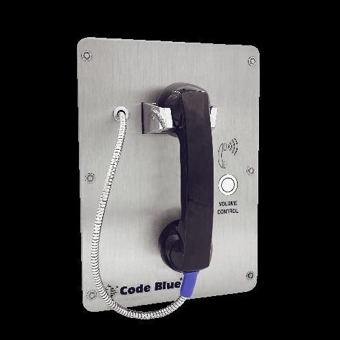
Administrator Guide
                                                                                      LS2000

                   Getting Started
                This guide contains information and a general overview for LS2000, including applications, installation,
                and wiring.

                LS2000 Features
                    •   Handset
                    •   SIP 2.0 Protocol Support
                    •   3 Ethernet Ports
                    •   3 auxiliary N.O. input contact closures
                    •   3 auxiliary N.O. output contact closures
                    •   NEMA 3S Compliant
                    •   UL 60950-22 and 62368-1 Compliant
                    •   Peer-to-peer audio communication
                    •   Multicast audio (Available with optional attached PAS Speaker)
                    •   Multiple ADA compliant lettering choices with Braille

Code Blue ● 259 Hedcor Street ● Holland, MI ● 4923 USA ● 800.205.7186 ● www.codeblue.com    Rev 6/2021      page 5 of 57   GU-165-A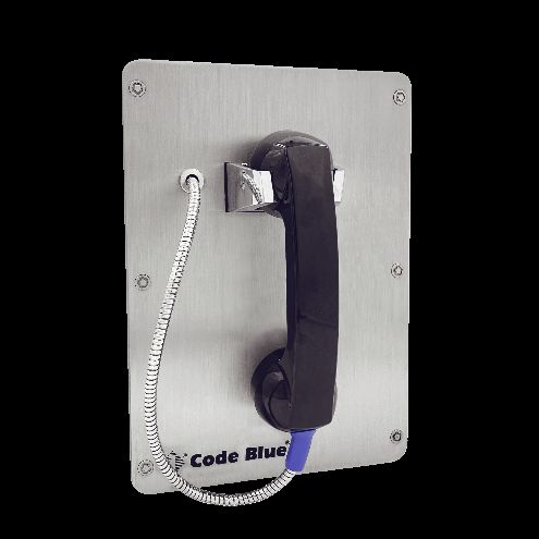
Administrator Guide
                                                                                     LS2000

                   Power Requirements
                The following table includes LS2000 and ALL OTHER Code Blue Devices and Enclosures for reference

                                                         Max             Max                Norm          Norm
              Faceplates                 Voltage        Current          Watts             Current        Watts          KWHrs
                 IA4100                    24V AC          0.40            9.60             0.22           5.28           0.13
                                           12V DC          0.90           10.80             0.39           4.68           0.11
                                           24V DC          0.90           21.60             0.39           9.36           0.22
                 IP5000                    24V AC          0.10            2.40             0.07           1.68           0.04
                                           12V DC          0.19            2.28             0.15            1.8           0.04
                                           24V DC          0.19            4.56             0.15            3.6           0.09
                 Centry                    12V DC          0.50            6.00             0.38           4.56           0.11
             LS1000/LS2000                 12V DC          0.50            3.60             0.40            4.8           0.12
                                                         Max             Max                Norm          Norm
                 Lights                  Voltage        Current          Watts             Current        Watts          KWHrs
       S-1000/S-2000 LED Strobe            24V AC          0.28            6.72             0.22          5.28            0.13
                                           12V DC          0.26            3.12             0.24          2.88            0.07
                                           24V DC          0.26            6.24             0.24          5.76            0.14
            A-700 Area Light               24V AC          1.80           43.20             0.83          19.92           0.48
                                           12V DC          2.68           32.16             0.38          4.56            0.11
                                           24V DC          2.68           64.32             0.38          9.12            0.22
    S-1050 LED Strobe W/ Photocell         24V AC          0.28            6.72             0.22          5.28            0.13
                                           12V DC          0.27            3.22             0.24          2.88            0.07
                                           24V DC          0.27            6.43             0.24          5.76            0.14
              LED Light Bar                24V AC          0.04            0.96             0.04          0.96            0.02
                                           12V DC          0.04            0.48             0.04          0.48            0.01
                                           24V DC          0.04            0.96             0.04          0.96            0.02
     WM180 PAS With LED Strobe             24V AC          7.30          175.20             2.10          50.4            1.21

Code Blue ● 259 Hedcor Street ● Holland, MI ● 4923 USA ● 800.205.7186 ● www.codeblue.com     Rev 6/2021   page 6 of 57    GU-165-A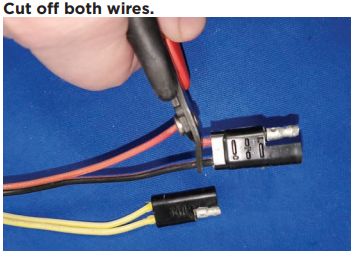
Administrator Guide
                                                                                     LS2000

        Models With IA4100 Faceplate                 Voltage          Current              Watts          KWHrs
                         CB 1-E                        24V AC            0.48               11.52            0.28
                                                       12V DC            0.67                8.04            0.19
                                                       24V DC            0.67               16.08            0.39
                         CB 1-S                        24V AC            1.31               31.44            0.75
                                                       12V DC            1.05               12.60            0.30
                                                       24V DC            1.05               25.20            0.60
                         CB 5-S                        24V AC            0.48               11.52            0.28
                                                       12V DC            0.67                8.04            0.19
                                                       24V DC            0.67               16.08            0.39
                         CB 9-S                        24V AC            0.26                6.24            0.15
                                                       12V DC            0.43                5.16            0.12
                                                       24V DC            0.43               10.32            0.25
                         CB 2-E                        24V AC            0.44               10.56            0.25
                                                       12V DC            0.63                7.56            0.18
                                                       24V DC            0.63               15.12            0.36
                         CB 2-A                        24V AC            0.48               11.52            0.28
                                                       12V DC            0.67                8.04            0.19
                                                       24V DC            0.67               16.08            0.39
                         CB 2-S                        24V AC            1.31               31.44            0.75
                                                       12V DC            1.05               12.60            0.30
                                                       24V DC            1.05               25.20            0.60
                     CB 2-E W/ PAS                     24V AC            6.44              154.56            3.71
                         CB 4-S                        24V AC            0.22                5.28            0.13
                                                       12V DC            0.39                4.68            0.11
                                                       24V DC            0.39                9.36            0.22
                         CB 4-R                        24V AC            0.26                6.24            0.15
                                                       12V DC            0.43                5.16            0.12
                                                       24V DC            0.43               10.32            0.25
                         CB 4-U                        24V AC            0.26                6.24            0.15
                                                       12V DC            0.43                5.16            0.12
                                                       24V DC            0.43               10.32            0.25
             Surface Mount/Flush Mount                 24V AC            0.22                5.28            0.13
                                                       12V DC            0.39                4.68            0.11
                                                       24V DC            0.39                9.36            0.22
                         CB RT                         24V AC            0.48               11.52            0.28
                                                       12V DC            0.67                8.04            0.19
                                                       24V DC            0.67               16.08            0.39

Code Blue ● 259 Hedcor Street ● Holland, MI ● 4923 USA ● 800.205.7186 ● www.codeblue.com   Rev 6/2021   page 7 of 57   GU-165-A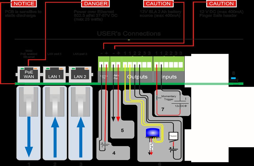
Administrator Guide
                                                                                     LS2000

            Models With IP5000 Faceplate                       Voltage           Current         Watts          KWHrs
                             CB 1-E                             24V AC             0.33             7.92           0.19
                                                                12V DC             0.43             5.16           0.12
                                                                24V DC             0.43            10.32           0.25
                             CB 1-S                             24V AC             1.16            27.84           0.67
                                                                12V DC             0.81             9.72           0.23
                                                                24V DC             0.81            19.44           0.47
                             CB 5-S                             24V AC             0.33             7.92           0.19
                                                                12V DC             0.43             5.16           0.12
                                                                24V DC             0.43            10.32           0.25
                             CB 9-S                             24V AC             0.11             2.64           0.06
                                                                12V DC             0.19             2.28           0.05
                                                                24V DC             0.19             4.56           0.11
                             CB 2-E                             24V AC             0.29             6.96           0.17
                                                                12V DC             0.39             4.68           0.11
                                                                24V DC             0.39             9.36           0.22
                             CB 2-A                             24V AC             0.33             7.92           0.19
                                                                12V DC             0.43             5.16           0.12
                                                                24V DC             0.43            10.32           0.25
                             CB 2-S                             24V AC             1.16            27.84           0.67
                                                                12V DC             0.81             9.72           0.23
                                                                24V DC             0.81            19.44           0.47
                          CB 2-E / PAS                          24V AC             6.44           154.56           3.71
                             CB 4-S                             24V AC             0.07             1.68           0.04
                                                                12V DC             0.15             1.8            0.04
                                                                24V DC             0.15             3.6            0.09
                             CB 4-R                             24V AC             0.11             2.64           0.06
                                                                12V DC             0.19             2.28           0.05
                                                                24V DC             0.19             4.56           0.11
                             CB 4-U                             24V AC             0.11             2.64           0.06
                                                                12V DC             0.19             2.28           0.05
                                                                24V DC             0.19             4.56           0.11
                  Surface Mount/Flush Mount                     24V AC             0.07             1.68           0.04
                                                                12V DC             0.15             1.8            0.04
                                                                24V DC             0.15             3.6            0.09
                             CB RT                              24V AC             0.33             7.92           0.19
                                                                12V DC             0.43             5.16           0.12
                                                                24V DC             0.43            10.32           0.25

Code Blue ● 259 Hedcor Street ● Holland, MI ● 4923 USA ● 800.205.7186 ● www.codeblue.com   Rev 6/2021      page 8 of 57   GU-165-A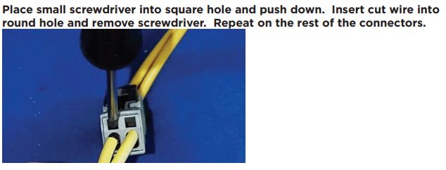
Administrator Guide
                                                                                      LS2000

            Models with LS1000/LS2000                  Voltage          Current            Watts         KWHrs
                          CB 1-E                         12V DC           0.68              8.16           0.20
                          CB 1-S                         12V DC           1.06             12.72           0.31
                          CB 5-S                         12V DC           0.68              8.16           0.20
                          CB 9-S                         12V DC           0.44              5.28           0.13
                          CB 2-E                         12V DC           0.64              7.68           0.18
                          CB 2-A                         12V DC           0.68              8.16           0.20
                          CB 2-S                         12V DC           1.06             12.72           0.31
                          CB 4-S                         12V DC           0.40              4.80           0.12
                          CB 4-R                         12V DC           0.44              5.28           0.13
                          CB 4-U                         12V DC           0.44              5.28           0.13
                Surface Mount/Flush Mount                12V DC           0.40              4.80           0.12
                          CB RT                          12V DC           0.68              8.16           0.20

                 High Voltage AC Components                  Voltage             Current      Watts KWHrs
                        Multi-Tap Power Supply                120V AC       1.75A/210VAC        210       5.04
                         Din Rail Power Supply                120V AC       1.2A/115VAC         115       2.76
                              Heater -DFB                     120V AC            1.6            192       4.61
                              DC - PS DFB                     120V AC            2.6            312       7.49
                               PAS Amp                        120V AC            3.83          459.6     11.03

Code Blue ● 259 Hedcor Street ● Holland, MI ● 4923 USA ● 800.205.7186 ● www.codeblue.com    Rev 6/2021   page 9 of 57   GU-165-A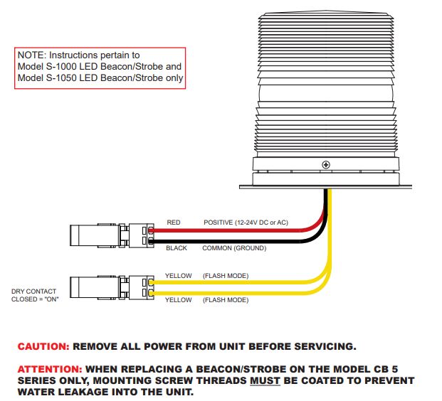
Administrator Guide
                                                                                      LS2000

                         High Voltage Models                  Voltage        Current       Watts KWHrs
                                  CB 1 DFB                     120V AC         3.35         402         9.6
                                  CB 2 DFB                     120V AC         3.35         402         9.6
                                  CB 1 PAS                     120V AC         3.83         460         11
                                  CB 5 PAS                     120V AC         3.33         400         9.6
                           CB 1-s w/ NightCharge               120V AC          2.5         300         2.4
                           CB 4-U w/ NIghtCharge               120V AC          2.5         300         2.4

Code Blue ● 259 Hedcor Street ● Holland, MI ● 4923 USA ● 800.205.7186 ● www.codeblue.com   Rev 6/2021   page 10 of 57   GU-165-A
Administrator Guide
LS2000
Installation Instructions
Legal Considerations Canada
This digital apparatus complies with CAN ICES-3 (Class A). The product shall be
Video and audio surveillance can be regulated by laws that vary from country to connected using a shielded network cable (STP) that is properly grounded. Cet
country. Check the laws in your local region before using this product for appareil numérique est conforme à la norme NMB ICES-3 (classe A). Le produit doit
être connecté à l’aide d’un câble réseau blindé (STP) qui est correctement mis à la
surveillance purposes. Liability
terre.
Every care has been taken in the preparation of this document. Please inform Code
Safety
Blue Corporation of any inaccuracies or omissions. Code Blue cannot be held
responsible for any technical or typographical errors and reserves the right to make
This product complies with 62638-1/UL 60950-1 and 62638-1/UL 60950-22, Safety of
changes to the product and manuals without prior notice. Code Blue makes no
Information Technology Equipment. The product shall be grounded either through a
warranty of any kind with regard to the material contained within this document,
shielded network cable (STP) or other appropriate method. The power supply used
including, but not limited to, the implied warranties of merchantability and fitness for a
with this product shall fulfill the requirements for Safety Extra Low Voltage (SELV) and
particular purpose. Code Blue shall not be liable or responsible for incidental or
Limited Power Source (LPS) according to IEC/EN/UL 60950-1. This unit complies with
consequential damages in connection with the furnishing, performance or use of this
IP54/NEMA 3 and IEC 61969-3 Class 1 specifications.
material. This product is only to be used for its intended purpose.
Warranty
Intellectual Property Rights
Code Blue Corporation provides a limited warranty on this product.
Code Blue Corporation has intellectual property rights relating to technology embodied
Refer to your sales agreement to establish the terms. In addition, Code Blue’s standard
in the product described in this document. This product contains open source code
warranty language, as well as information regarding support for this product while
that also contains additional open source libraries.
under warranty, is available at www.codeblue.com/support/downloads.
Equipment Modifications
In Case of Breakdown
This equipment must be installed and used in strict accordance with the instructions
In case of system breakdown, discontinue use and contact Tech Support at
given in the user documentation. This equipment contains no user-serviceable
ts@codeblue.com or call (800) 205-7186, option 3.
components. Unauthorized equipment changes or modifications will invalidate all
applicable regulatory certifications and approvals.
In Case of Abnormal Operation
Trademark Acknowledgments
If the unit emits smoke or an unusual smell, if water or other foreign material enters the
enclosure, or if you drop the unit or damage the enclosure, power off the unit
Code Blue and Centry products are registered trademarks or trademark applications of
immediately and contact:
Code Blue Corporation in various jurisdictions. All other company names and products
are trademarks or registered trademarks of their respective companies.
Code Blue Customer Service at customerservice@codeblue.com or (800) 205-7186,
option 2.
Regulatory Information
Electromagnetic Compatibility (EMC) Disposal and Recycling
This equipment has been designed and tested to fulfill applicable standards for:
When this product has reached the end of its useful life, dispose of it according to local
laws and regulations. For information about your nearest designated collection point,
• Radio frequency emission when installed according to the instructions and
contact your local authority responsible for waste disposal. In accordance with local
used in the intended environment.
legislation, penalties may be applicable for incorrect disposal of this waste.
• Immunity to electrical and electromagnetic phenomenon when installed
according to the instructions and used in its intended environment.
This guide should contain all the information needed for your application. If any further
information is needed, please contact customerservice@codeblue.com.
USA
Support
This equipment has been tested using a shielded network cable (STP) and found to
comply with the limits for a Class A digital device, pursuant to part 15 of the FCC
Should you require any technical assistance, please contact Code Blue. Visit
Rules. These limits are designed to provide reasonable protection against harmful
codeblue.com to:
interference when the equipment is operated in a commercial environment. This
equipment generates, uses and can radiate radio frequency energy and, if not installed
• Download user documentation and software.
and used in accordance with the instruction manual, may cause harmful interference to
• Find answers to resolved problems in the FAQ database.
radio communications. Operation of this equipment in a residential area is likely to
Report problems to Code Blue Technical Support
cause harmful interference in which case the user will be required to correct the
interference at their own expense. The product shall be connected using a shielded via email at ts@codeblue.com or 800-205-7186
network cable (STP) that is properly grounded.
Code Blue ● 259 Hedcor Street ● Holland, MI ● 4923 USA ● 800.205.7186 ● www.codeblue.com Rev 6/2021 page 11 of 57 GU-165-AAdministrator Guide
LS2000
Safety Information
Hazard Levels
DANGER
Indicates a hazardous situation which, if not avoided, will result in death or serious injury.
WARNING
Indicates a hazardous situation which, if not avoided, could result in death or serious injury.
CAUTION
Indicates a hazardous situation which, if not avoided, could result in minor or moderate injury.
NOTICE
Indicates a situation which, if not avoided, could result in damage to property.
Other Message Levels
Important
Indicates significant information that is essential for the product to function correctly.
Note
Indicates useful information that helps get the most out of the product.
Safety Instructions
WARNING
• Code Blue products shall be installed by trained professionals.
NOTICE
• Code Blue products shall be used in compliance with local laws and regulations.
• Store the Code Blue product in a dry and ventilated environment.
• Do not install the product on unstable brackets, surfaces or walls.
• Use only applicable tools when installing Code Blue products.
• Do not use chemicals, caustic agents, or aerosol cleaners other than those tested and recommended
by Code Blue.
• Use only accessories that comply with technical specifications of the product. These can be provided
by Code Blue or a third party.
• Use only spare parts provided by or recommended by Code Blue.
• Do not attempt to repair the product by yourself. Contact Code Blue or your Code Blue reseller for
service.
Transportation
NOTICE
• When transporting a Code Blue product, use the original packaging or equivalent to prevent damage
to the product.
Code Blue ● 259 Hedcor Street ● Holland, MI ● 4923 USA ● 800.205.7186 ● www.codeblue.com Rev 6/2021 page 12 of 57 GU-165-AAdministrator Guide
LS2000
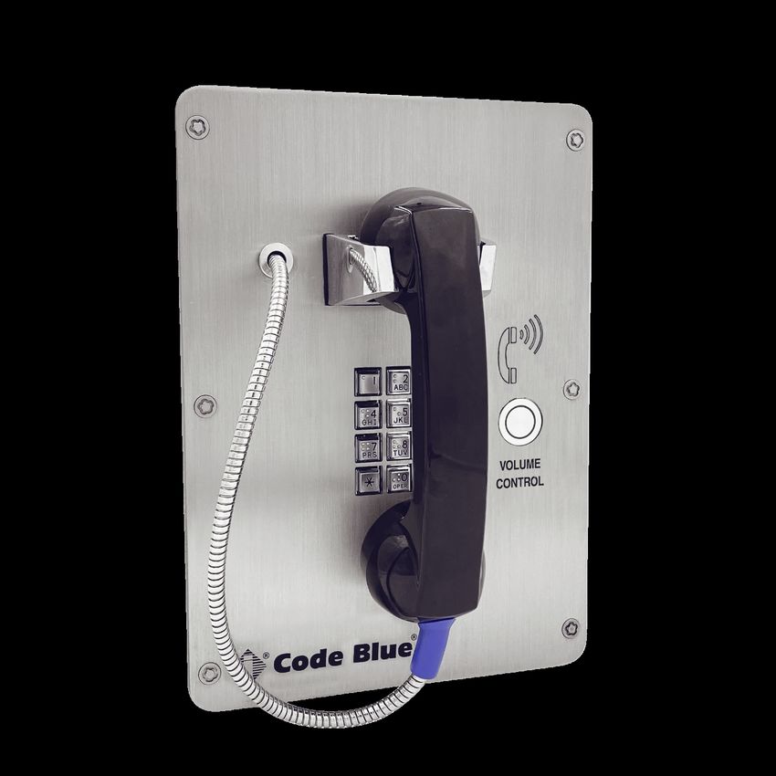
What’s Included
LS2000 - Handset Phone
Quantity Part
1 Enclosure (Surface or Flush)
6 Security Screws
1 Faceplate / Circuit board with Integrated IP Color Camera
LS2000 faceplate tools needed for installation:
1. Drill and screws to mount unit to wall.
2. Code Blue Security bit and any 1/4” bit drive handle.
Basic Flush Mount Installation Instructions for use by Installers:
1. Remove six security screws with Code Blue security bit and any 1/4” bit driver tool.
2. Separate LS2000 from enclosure and set aside carefully. The flush mount enclosure will come with no mounting
holes. It can be mounted from the sides, top or bottom. Once your mounting needs have been determined, drill the
holes needed for your specific installation requirements into the flush mount back box.
3. Mark the mounting holes onto the mounting surface. In order to comply with the Americans with Disabilities Act
(ADA) of 1990, the speakerphone button(s) should be positioned between 34 and 48 inches from grade level.
(Consult an ADA specialist in your area to verify local and federal guidelines.)
4. Connect earth ground to the provided copper grounding lug using a minimum 14-gauge conductor.
5. Connect electrical and communications wiring using the wiring diagram below.
6. Follow all federal and local codes that apply.
7. Attach faceplate to enclosure using six security screws.
Basic Surface Mount Installation Instructions for user by Installers:
1. Remove six security screws with Code Blue security bit and any 1/4” bit driver tool.
2. Separate LS2000 from enclosure and set aside carefully.
3. Mark the mounting holes onto the mounting surface. In order to comply with the Americans with Disabilities Act
(ADA) of 1990, the speakerphone button(s) should be positioned between 34 and 48 inches from grade level.
(Consult an ADA specialist in your area to verify local and federal guidelines.)
4. Drill all marked holes.
Code Blue ● 259 Hedcor Street ● Holland, MI ● 4923 USA ● 800.205.7186 ● www.codeblue.com Rev 6/2021 page 13 of 57 GU-165-AAdministrator Guide
LS2000
5. Secure the housing to the wall – If you are securing to drywall, utilize drywall screws and anchors. If you are
securing to metal, utilize sheet metal screws. If you are securing to brick, use Tapcon screws. Fasten all screws
securely.
Important: Ensure that conduit is aligned with wiring.
7. Connect earth ground to the provided copper grounding lug using a minimum 14-gauge conductor.
8. Connect electrical and communications wiring using the wiring diagram below.
9. Follow all federal and local codes that apply.
Attach faceplate to enclosure using six security screws.
Code Blue ● 259 Hedcor Street ● Holland, MI ● 4923 USA ● 800.205.7186 ● www.codeblue.com Rev 6/2021 page 14 of 57 GU-165-AAdministrator Guide
LS2000
How to Update Connectors
As of 2020, many Code Blue products come with Wago connectors. These connectors provide
ease of use and a much stronger connection. Below are the steps needed to change to the new
connectors.
Code Blue ● 259 Hedcor Street ● Holland, MI ● 4923 USA ● 800.205.7186 ● www.codeblue.com Rev 6/2021 page 15 of 57 GU-165-AAdministrator Guide
LS2000
Code Blue ● 259 Hedcor Street ● Holland, MI ● 4923 USA ● 800.205.7186 ● www.codeblue.com Rev 6/2021 page 16 of 57 GU-165-AAdministrator Guide
LS2000
Wiring Diagrams
1 - Cat 5e - Connect to Switch (100 Mb)
2 - Cat 5e - Connect to Peripheral (100 Mb) 3 - Cat 5e - Connect to Peripheral (100 Mb)
4 - Optional 12V battery
5 - 12V DC power
6 - Aux outputs (3)
• The auxiliary outputs are Normally Open and can be triggered in your action script to close. Duration is
defined in your action script.
7 - Aux inputs (3)
• The auxiliary inputs are Normally Open and are triggered by voltage. The voltage range is 9 to 32V AC or
DC with current protection of 1.25 Amps.
8 - Factory Reset Switch
• With power connected to LS2000, hold down this reset switch for 12 seconds and then release. The unit
will reboot. All settings will be lost.
Code Blue ● 259 Hedcor Street ● Holland, MI ● 4923 USA ● 800.205.7186 ● www.codeblue.com Rev 6/2021 page 17 of 57 GU-165-AAdministrator Guide
LS2000
Schematics
7.1.1 Flush Mount Mounting Schematics
7.1.2 Surface Mount Mounting Schematics
Code Blue ● 259 Hedcor Street ● Holland, MI ● 4923 USA ● 800.205.7186 ● www.codeblue.com Rev 6/2021 page 18 of 57 GU-165-AAdministrator Guide
LS2000
Code Blue ● 259 Hedcor Street ● Holland, MI ● 4923 USA ● 800.205.7186 ● www.codeblue.com Rev 6/2021 page 19 of 57 GU-165-AAdministrator Guide
LS2000
Setting Up Your LS2000
Determine the IP Address
Once you can browse into the device, you can switch to a static IP if desired.
Connect the LS2000 to your DHCP Network. The “Call Placed” red LED will flash while the device is
booting up. The LS2000 will acquire its network settings from the DHCP server on the network. If the
network is not running DHCP the device will default to the IP address of 192.168.0.249 after one minute.
If you do not have network scanner software, you can download many free ones. “Advanced IP Scanner”
is one example. Run a scan of the subnet the LS2000 device is plugged into, and your PC if plugged into
the same network.
You can find the IP address for your LS2000 speakerphone by matching its MAC address. You can then
browse to the IP address of the device. The recommended web browsers are Google Chrome and
Mozilla Firefox. You may experience erratic behavior with other browsers.
Default login information is:
Code Blue ● 259 Hedcor Street ● Holland, MI ● 4923 USA ● 800.205.7186 ● www.codeblue.com Rev 6/2021 page 20 of 57 GU-165-AAdministrator Guide
LS2000
Username: admin
Password: admin
Network - General Settings
Once logged into the device, you can change the Network Settings in General Settings under
Network if you want to switch over to a static IP address.
Code Blue ● 259 Hedcor Street ● Holland, MI ● 4923 USA ● 800.205.7186 ● www.codeblue.com Rev 6/2021 page 21 of 57 GU-165-AAdministrator Guide
LS2000
Generally, you can leave the Host and Domain fields empty.
SSH Port 22 is enabled by default. You can change the Port and disable it, if desired.
If limiting Network Ports, then the ports to have open are:
• tcp 22 SSH Secure Shell Protocol (Configurable)
• tcp 53 DNS Domain Name Service over TCP
• udp 53 DNS Domain Name Service over UDP
• tcp 80 HTTP Hyper Text Transfer Protocol
• tcp 161 SNMP Simple Network Management Protocol
• tcp 162 SNMP Trap Simple Network Management Protocol Trap
• tcp 443 SSL Secure Socket Layer (Deprecated)
• udp 554 RTSP Real Time Streaming Protocol
• udp 554 RTSP Real Time Streaming Protocol
• udp 5060 SIP Session Initiation Protocol
• tcp 5061 SIP Session Initiated Protocol
• rtp 16384-32767 Real Time Transport (Configurable)
Code Blue ● 259 Hedcor Street ● Holland, MI ● 4923 USA ● 800.205.7186 ● www.codeblue.com Rev 6/2021 page 22 of 57 GU-165-AAdministrator Guide
LS2000
Accounts
Add Account
These settings are usually provided by IP PBX, SIP server or SIP gateway personnel. When setting
up a SIP or peer-to-peer account, make sure the correct Account Type is selected
Account Name: Free form field to identify the account.
Username/Number: Phone number or extension for the LS2000. This is still required for peer-to-peer; Any
number value can be entered.
Speaker Volume: You can set the speaker volume gain here in the GUI, as well as from a touch-tone
phone using in-call commands. This becomes the default volume level.
Mic Volume: You can set the mic volume gain here in the GUI, as well as from a touch-tone phone.
using in-call commands. This becomes the default volume level.
Enable SIP Video: Select this option to allow SIP video packets to be transmitted. RTSP video will
still be available but note that only one format will be available at a time.
SIP Video Resolution: Use drop down menu to select resolution for SIP video. This does not apply to
RTSP video quality.
Force Resolution: Some desk phones will overwrite the resolution set in the LS2000 to their native
resolution. Select this option to force the selected resolution.
Code Blue ● 259 Hedcor Street ● Holland, MI ● 4923 USA ● 800.205.7186 ● www.codeblue.com Rev 6/2021 page 23 of 57 GU-165-AAdministrator Guide
LS2000
SIP Server Settings
Server IP Address: You can use the domain name or IP address of your IP PBX, SIP Gateway, SBC or
whatever you register SIP devices to.
Password: This is the shared SIP secret password that the phone and your SIP registration server share.
Server Port: 0 for auto detect. Commonly may be 5060. If necessary, you may have to specify a port
here.
Advanced SIP Settings
Transport Protocol: IPv4 or IPv6.
Communication Protocol: UDP or TCP.
Registration Lifetime: Default is 600 seconds. This is the time the phone will attempt re-registration if not
contacted by the SIP server.
Keep Alive: Check if you want keep-alive messages sent between the SIP server and the phone.
Use a Proxy Server: If using a proxy server in addition to a SIP server, then specify the IP Address
or Domain, SIP Authentication ID and Outbound Proxy Port used.
Code Blue ● 259 Hedcor Street ● Holland, MI ● 4923 USA ● 800.205.7186 ● www.codeblue.com Rev 6/2021 page 24 of 57 GU-165-AAdministrator Guide
LS2000
Manage Accounts
After adding an account, you can manage the created accounts on this page.
Note: You can create a near infinite to different SIP servers. Generally, only one is used.
Click onto an account to manage it for viewing or to make changes.
Code Blue ● 259 Hedcor Street ● Holland, MI ● 4923 USA ● 800.205.7186 ● www.codeblue.com Rev 6/2021 page 25 of 57 GU-165-AAdministrator Guide
LS2000
System Status
After creating your account and providing the SIP server, check the registration status on the System Status
page. This is located in the top right corner of the screen.
In this screen, you can see the current IP address of the phone, which is the same for the camera.
It also will display the current registration status of the configured accounts. Registration status of “good” is
what you are looking for. If it is not, investigate the matching account settings configured in the SIP server and
if the network has been opened in between.
Code Blue ● 259 Hedcor Street ● Holland, MI ● 4923 USA ● 800.205.7186 ● www.codeblue.com Rev 6/2021 page 26 of 57 GU-165-AAdministrator Guide
LS2000
Audio
Default RTP Ports and Codecs are listed here. These can be adjusted based on the needs of the SIP or
PBX server.
Code Blue ● 259 Hedcor Street ● Holland, MI ● 4923 USA ● 800.205.7186 ● www.codeblue.com Rev 6/2021 page 27 of 57 GU-165-AAdministrator Guide
LS2000
Multicast Audio
To add a new multicast configuration, enter a Label, the Listening IP address and Port.
To change the priority of the multicast, simply drag and drop. A phone call priority level also can be set
with the Order Priority box checked. By default, the Phone Call Priority is set to 0.
Code Blue ● 259 Hedcor Street ● Holland, MI ● 4923 USA ● 800.205.7186 ● www.codeblue.com Rev 6/2021 page 28 of 57 GU-165-AAdministrator Guide
LS2000
General Events
In the General Events setting you can alter the outgoing call tone, apply a call ending warning, allow or
disallow incoming calls and apply location recordings.
Code Blue ● 259 Hedcor Street ● Holland, MI ● 4923 USA ● 800.205.7186 ● www.codeblue.com Rev 6/2021 page 29 of 57 GU-165-AAdministrator Guide
LS2000
Action Scripts
Action Scripts determine what happens when the handset is lifted, a number is dialed, or an aux input is
activated. The button on the LS2000 is used to raise the output volume of the handset.
Select the Hook Switch or aux input you would like to associate and action with.
Choose “Add Action”
You can choose to have an aux output triggered, automatically place a call when the handset is lifted, go
to open dial tone, or simply play a message. You can also string multiple actions together.
Code Blue ● 259 Hedcor Street ● Holland, MI ● 4923 USA ● 800.205.7186 ● www.codeblue.com Rev 6/2021 page 30 of 57 GU-165-AAdministrator Guide
LS2000
Place Call Action
Select the Account that was created earlier that the calls will be routed through.
If a Keypad is present, then the option for Manual Dial is available. The number of digits that can be
dialed can be limited. For example, only allowing 4-digit extensions to be dialed.
For Auto Dial calls enter in the “To” field the number you would like LS2000 to dial for Auto Calls. For
peer-to-peer, enter the IP Address:Port the call is intended to go to.
If that number does not answer, you can “Add Call” and select another account and phone number to dial.
This is useful if you have the phone registering to multiple SIP servers/SIP PBXs. For example, you can
have it call 911 from Account 1 and call 911 from Account 2 if Account 1 is down. The phone will roll over
to Account 2 and call out that account.
Repeat for the number of times you want the call to rollover before answering.
Each iteration of the rolled over call uses the “Dialing/Answer Timeout.”
Note: If voicemail answers, then that is considered an answered call.
Code Blue ● 259 Hedcor Street ● Holland, MI ● 4923 USA ● 800.205.7186 ● www.codeblue.com Rev 6/2021 page 31 of 57 GU-165-AAdministrator Guide
LS2000
“Maximum Call Duration” is 600 seconds or 10 minutes by default. This is used as a timer in case the
receiving party never hangs up the call. This timer is editable.
“While Dialing”
You can select the audio of ring-back or use a custom recording that is uploaded into the phone in the
Recordings page. A common recording script would be something like, “Security has been contacted;
please stand by.”
This message will repeat just like ring-back would until the call is answered. This message will stop when
the call is answered.
“When Answered”
The default mode is two-way audio upon the call being answered.
Additional options include playing a custom recording locally out of the LS2000 speaker and/or playing a
custom recording remotely to the receiving party that identifies where this call is coming from.
Note: This is a useful feature if the receiving party is not going to get a unique caller ID
name/number for this location.
Once the recording has played, two-way audio will commence.
Note: If playing a remote message but not a local message, then the person at the LS2000 will
hear dead air until the remote message is done playing. It is advisable to play the same message
to both parties in this case.
Note: It is advisable to keep your recordings short to establish connection to a two-way call as
quickly as possible.
“In-Call Commands”
Default is to have the in-call commands available during the phone call. These can be disabled for this
action. In-call commands are also available on an inbound call into LS2000. See section on in-call
commands for the full list.
Code Blue ● 259 Hedcor Street ● Holland, MI ● 4923 USA ● 800.205.7186 ● www.codeblue.com Rev 6/2021 page 32 of 57 GU-165-AAdministrator Guide
LS2000
Control AUX Output
Choose the AUX output you want to control.
Choose enabled or disabled for this action. Enabled closes the normally open contact; disabled opens the
normally open contact.
Choose the duration you want the action to last. (0 seconds = indefinite.)
Note: This is the most common setting for controlling an auxiliary, such as a blue light strobe, to
stay activated for the duration of the call if linked to a place call action
Play Message
Play a message when this step is reached as part of your greater action script or as the only action in
your action script.
Upload your recordings by going to the Recordings page. The message only plays out of the LS2000
speaker.
Note: There are blue arrows that can move your action up and down in the action script.
Code Blue ● 259 Hedcor Street ● Holland, MI ● 4923 USA ● 800.205.7186 ● www.codeblue.com Rev 6/2021 page 33 of 57 GU-165-AAdministrator Guide
LS2000
Note: You can string together many actions in the action script.
A typical action script for a LS2000 may just have a Place Call Action, or if your LS2000 has a remote
beacon/strobe light, then it would look like the example below to have the strobe linked to the duration of
the call.
At the bottom of the action script page, you can test your action script and it will launch through the
script and place a call, play a message, or trip auxiliaries.
Note: This will call whatever number you have entered in
Code Blue ● 259 Hedcor Street ● Holland, MI ● 4923 USA ● 800.205.7186 ● www.codeblue.com Rev 6/2021 page 34 of 57 GU-165-AAdministrator Guide
LS2000
Code Blue ● 259 Hedcor Street ● Holland, MI ● 4923 USA ● 800.205.7186 ● www.codeblue.com Rev 6/2021 page 35 of 57 GU-165-AAdministrator Guide
LS2000
Recordings
Upload recordings into the phone on this page.
Recordings uploaded are then available in action scripts.
The phone only can play uncompressed 16-bit PCM or compressed g.711 A-law/U-law format .wav
files.
If you upload unsupported audio file formats, they will not play in the action script.
Code Blue ● 259 Hedcor Street ● Holland, MI ● 4923 USA ● 800.205.7186 ● www.codeblue.com Rev 6/2021 page 36 of 57 GU-165-AAdministrator Guide
LS2000
Administration
Upload a secure PEM certificate and PEM key.
This page also allows for the default password to be changed. New passwords must be at least six
characters long.
From the General Administration page, you can pull OS and SIP logs that can be used to diagnose issues
with functionality and SIP registration/Call Routing.
The LS2000 can be rebooted from this page as well.
Code Blue ● 259 Hedcor Street ● Holland, MI ● 4923 USA ● 800.205.7186 ● www.codeblue.com Rev 6/2021 page 37 of 57 GU-165-AAdministrator Guide
LS2000
Date and Time
Adjust the date and time on this page or point the phone to a NTP server to have a permanent time
source.
Code Blue ● 259 Hedcor Street ● Holland, MI ● 4923 USA ● 800.205.7186 ● www.codeblue.com Rev 6/2021 page 38 of 57 GU-165-AAdministrator Guide
LS2000
Diagnostics
With SNMP Traps enabled, enter the SNMP server name, port number (162 by default) and Read/Write
Community Names.
Each trap can be enabled or disabled to customize the output.
The time interval for Power, Microphone and Speaker can be adjusted. By default, these are set to 900
seconds for Power Failure tests and 0 Seconds (Disabled) for Mic/Speaker tests. The volume of the
Mic/Speaker test can be adjusted via a drop-down menu.
Code Blue ● 259 Hedcor Street ● Holland, MI ● 4923 USA ● 800.205.7186 ● www.codeblue.com Rev 6/2021 page 39 of 57 GU-165-AAdministrator Guide
LS2000
Firmware
Upload new firmware into the phone from www.codeblue.com/resources. Once you download onto your
PC, unzip the file. From the LS2000 firmware page, browse to the .bin file on your PC and upgrade your
LS2000.
Code Blue ● 259 Hedcor Street ● Holland, MI ● 4923 USA ● 800.205.7186 ● www.codeblue.com Rev 6/2021 page 40 of 57 GU-165-AAdministrator Guide
LS2000
Hardware Settings
Hardware settings allow you to enable or disable the Station Light, adjust the brightness, and blink rate.
Each button can be configured as a Non-Emergency Button, Emergency or Volume Control. The color of
the ring LED around each button can be changed in the drop-down menu.
Any additional peripherals attached to LS2000 must be marked as “Installed” to ensure functionality.
Code Blue ● 259 Hedcor Street ● Holland, MI ● 4923 USA ● 800.205.7186 ● www.codeblue.com Rev 6/2021 page 41 of 57 GU-165-AAdministrator Guide
LS2000
In-Call Commands
You can make adjustments during a live phone call with the LS2000 device. This can be done by
calling into the LS2000 or by a call initiated by the LS2000 to the receiving party. The party with the
touch-tone phone can use the keys on their keypad via DTMF tones to make adjustments.
In-Call Command Function Description
4 Aux 1 Output Toggle contact closed/open
5 Aux 2 Output Toggle contact closed/open
6 Increase Mic Gain Small adjustments to LS2000 microphone
7 Decrease Mic Gain Small adjustments to LS2000 microphone
8 Increase Speaker Gain Small adjustments to LS2000 speaker
9 Decrease Speaker Gain Small adjustments to LS2000 speaker
Note: These adjustments do not persist after the call has ended. The LS2000 phone will return to
the default levels set in the account screen via the phone’s web GUI. See the Accounts chapter for
further information.
Code Blue ● 259 Hedcor Street ● Holland, MI ● 4923 USA ● 800.205.7186 ● www.codeblue.com Rev 6/2021 page 42 of 57 GU-165-AAdministrator Guide
LS2000
Compatibility
LS2000 is a SIP version 2.0 (RFC3261) device and is compatible with IP Gateways and PBXs that
can register third party SIP devices.
You must verify that the IP PBX you are registering LS2000 to can handle third party SIP
devices, whether through licensing and/or hardware add-ons. Please note that LS2000
currently does not work with a separate Proxy Server. SIP registration and calls must point to
the same domain/IP Address SIP Server.
Examples of mainstream IP PBXs LS2000 has registered to as a third-party SIP device include:
Avaya
Asterisk
Cisco Call Manager
Nortel and many others…
Code Blue ● 259 Hedcor Street ● Holland, MI ● 4923 USA ● 800.205.7186 ● www.codeblue.com Rev 6/2021 page 43 of 57 GU-165-AAdministrator Guide
LS2000
Configuring for Cisco Unified Call Manager
1. PREPARATION
1. Record the MAC address and determine the current IP address for each LS2000 device you wish to
use with CUCM.
2. Determine which partition you will put the LS2000 directory numbers into.
3. Obtain one directory number for each Ce LS2000 device.
a. If you are going to use the LS2000’s dual account configuration to register to redundant
CUCM servers, obtain a second directory number for each LS2000 device.
4. Determine which calling search space you will assign to the LS2000.
2. LS2000 CONFIGURATION
3. Configure Account(s)
1. Log in to LS2000 via its web interface. The default username and password are admin and
admin.
2. Select Account 1.
3. For VoIP Protocol, select SIP and RTP.
4. Under SIP Configuration, for Username/Number enter the directory number assigned in the
CUCM.
5. For Display Name, enter caller ID text.
6. For Domain, enter the hostname or IP address of the CUCM subscriber you wish to register
this account.
7. Insure Keep-Alive is enabled.
8. For Password, enter the password you entered into Digest Credentials under the CUCM
end user.
9. Click Save.
10. Repeat steps 3-9 with Account 2 if you are using the second account.
Other Settings
Code Blue ● 259 Hedcor Street ● Holland, MI ● 4923 USA ● 800.205.7186 ● www.codeblue.com Rev 6/2021 page 44 of 57 GU-165-AAdministrator Guide
LS2000
Refer to Section 6 to complete the setup of the LS2000, including Numbers, General Settings, Hardware
Settings and Action Scripts. When finished, it should now register to CUCM and be able to place calls in
the assigned calling search space as well as receive calls at the directory number it is configured with.
Note: If you are setting up the LS2000 with secondary account support, make sure that you create
each failover number twice.
4. UCM CONFIGURATION
All UCM-side configuration is done within the Cisco Unified CM Administration web interface.
5. Create Phone Security Profile
1. Navigate to System > Security > Phone Security Profile.
2. Do a Find on “Third-party” to locate the Third-party SIP Device Basic - Standard SIP Non-
Secure Profile. Click the Copy icon.
3. Check Enable Digest Authentication.
4. Change the Name and Description to Code Blue LS2000 Profile.
5. Click Save.
6. Configure End Users
For each LS2000 device, configure a new end user for SIP authentication.
1. Navigate to User Management > End User.
2. Click Add New.
3. For the User ID, enter the Directory Number of the LS2000 phone.
4. Fill in the Last Name field with the Directory Number.
a. The Directory Number, User ID, and Last Name fields must all be the same.
Create and record a secure SIP password and fill in the Digest Credentials and Confirm Digest Credentials
fields with this password. You will be entering this password later into the LS2000.
5. Click Save.
7. Configuring End Users for Secondary Accounts
If you are going to use the Cen LS2000’s try’s secondary account functionality to register to a separate
directory number to a separate CUCM node for failover support, repeat the above process using a local-
Code Blue ● 259 Hedcor Street ● Holland, MI ● 4923 USA ● 800.205.7186 ● www.codeblue.com Rev 6/2021 page 45 of 57 GU-165-AAdministrator Guide
LS2000
use-only MAC address. A local-use-only MAC address has the U/L bit set to 1 to indicate the address is
locally administered.
8. Configure Phones and Directory Numbers
For each LS2000 device, configure a new Phone and associated directory number.
1. Navigate to Device > Phone.
2. Click Add New.
3. For Phone Type, select Third-party SIP Device (Basic).
4. Enter the MAC Address of the phone in hexadecimal format; e.g. 00:50:C2:17:7B:E8 would
become 0050c2177be8.
5. For Device Pool, select Default (or some other locally-configured device pool).
6. For Phone Button Template, select Third-party SIP Device (Basic).
7. For Calling Search Space, select the calling search space the LS2000 is to use.
8. For Device Security Profile, select Code Blue LS2000 Profile.
9. For SIP Profile, select Standard SIP Profile.
10. For Digest User, select the end user matching the MAC address of the phone.
11. Click Save.
12. On the left side of the screen, click Line [1] - Add a new DN.
13. Fill in the Directory Number.
14. For Route Partition, select the partition the directory number resides in.
15. Under Line 1, for Display (Internal Caller ID), enter a descriptive name for Caller ID
purposes.
16. If you wish to return a busy signal for silent monitoring if the LS2000 is in use, disable Call
Waiting: under Multiple Call/Call Waiting Settings, For both Maximum Number of Calls and Busy
Trigger, enter 1.
17. Click Save.
Code Blue ● 259 Hedcor Street ● Holland, MI ● 4923 USA ● 800.205.7186 ● www.codeblue.com Rev 6/2021 page 46 of 57 GU-165-AAdministrator Guide
LS2000
9. Configuring Phones and Directory Numbers for Secondary Accounts
If you are going to use the LS2000’s secondary account functionality, repeat the above process with
a local-use-only MAC address as outlined in Configuring End Users for Secondary Accounts, and
specify a distinct directory number.
10. Integrating InformaCast Utilizing Cisco Call Manager
Access to the InformaCast emergency notification system produced by Singlewire Software
frequently is included with Cisco Unified Communication Manager (CUCM). Code Blue’s VoIP
speakerphones (LS2000) can be registered and configured with CUCM as SIP devices that are
compatible with IP Gateways and PBXs that can register third-party SIP devices.
To send audio pages from InformaCast to Code Blue speakerphones, select the Code Blue devices as
end point phones for the messages. The Code Blue phones will have the ability to answer and play the
audio by default.
Code Blue ● 259 Hedcor Street ● Holland, MI ● 4923 USA ● 800.205.7186 ● www.codeblue.com Rev 6/2021 page 47 of 57 GU-165-AAdministrator Guide
LS2000
Troubleshooting
The LS2000 is a network device. The following are tips for troubleshooting:
Power - Ensure the power to your device is working and rated for 802.11af/at PoE specifications if
using PoE. LS2000 should only have one source of power other than a backup battery. If not using
PoE, then main power needs to fall into 12-24 Volts DC.
Ping Test - This determines connectivity and the packet loss and latency time to and from your
destination and the quality of your network connection to LS2000. If you receive no response and
power is confirmed, contact your network administrator. You can also ping from within the phone
towards your IP PBX to test that it can reach its IP PBX/SIP Gateway.
Network – If you are putting LS2000 on a network that restricts ports, then the following ports must
be open for LS2000 to communicate to its appropriate IP PBX/SIP Gateway:
1. IAX2/UDP outgoing to port 4569 on IP PBX/SIP Gateway (only needed if using IAX2
instead of SIP on the accounts page).
2. SIP/UDP outgoing to port 5060 IP PBX/SIP Gateway.
3. RTP/UDP incoming from IP PBX/SIP Gateway to UDP ports 23456-23556 (configurable).
DHCP - LS2000 is set up for DHCP by default. If you cannot determine the IP address of your
LS2000, contact your network administrator.
Account - Ensure your SIP account is set up correctly. Account username and password must
match the account credentials on your VoIP system. This is the most common mistake with setting
up SIP accounts.
Codec - Ensure the codec settings on your VoIP system match the LS2000 codec settings.
Firewall - Firewalls commonly block or partially block VoIP calls. Check with your network
administrator if you cannot communicate with your LS2000 from behind a firewall.
Note: If you do not have a DHCP server running, use a standard home/wireless router and plug your
speakerphone and laptop into the same router. Once you know the IP Address, you can browse to it via
a web browser.
Code Blue ● 259 Hedcor Street ● Holland, MI ● 4923 USA ● 800.205.7186 ● www.codeblue.com Rev 6/2021 page 48 of 57 GU-165-AAdministrator Guide
LS2000
Software Configuration
Blue Alert MNS Software
Designed specifically for schools, hospitals, corporate and municipal campuses looking for an
efficient way to detect and respond, Code Blue’s Blue Alert® MNS is part of our First Responder
package that fills a need in the marketplace for an incident response solution that is both
comprehensive and cost-effective. The result is a sophisticated software solution that quickly
informs and directs people in emergency situations. Blue Alert MNS is available in two editions,
Audio/Visual and Messaging that are available individually or together in the Blue Alert MNS
Professional Package.
Blue Alert EMS
Blue Alert EMS (Event Management System) from Code Blue handles all incoming emergency and
non-emergency events with an easy-to-use Graphical User Interface (GUI). Effectively utilize EMS
for remote operation of Code Blue emergency communication devices. Open gates and AED
access doors, turn the LED beacon/strobe on or off. Have a camera connected to your Code Blue
unit or one mounted nearby? Simply integrate EMS with your CCTV system for instant video when
your Code Blue units are activated. The Event Management System utilizes an advanced API for
efficient integration with third party applications.
Code Blue ● 259 Hedcor Street ● Holland, MI ● 4923 USA ● 800.205.7186 ● www.codeblue.com Rev 6/2021 page 49 of 57 GU-165-AAdministrator Guide
LS2000
Remote Mount Beacon/Strobe Installation
1.0 ATTACH J-BOX TO THE POLE
1.1 Thread the banding (B) through the pole bracket (A) located on the backside of the J-box (C).
1.2 Wrap the banding around the pole. Cut the banding to desired length.
1.3 Using a screwdriver or nut driver, tighten the banding and make sure that the unit is in the
desired location.
NOTE: J-box must be positioned so weep hole faces down.
2.0 ATTACH LIGHT TO BRACKET
3.1 Using the three M4 X 8 screws enclosed (K), fasten the strobe (J) to the round portion of the
strobe bracket.
NOTE: If the beacon/strobe is mounted upside-down, a drain hole must be drilled into the lens
to prevent it from filling with water.
3.0 ATTACH LIGHT AND BRACKET TO THE J-BOX
4.1 Connect all wiring from the strobe to the wiring from the unit inside of the J-box using wire nuts.
4.2 Attach strobe bracket to the J-box using four 6-32 X ½ screws as shown.
A - pole-bracket
B - banding
C - J-box
D - pole-bracket mount nut (4 each)
E - pole-bracket mount screw (4 each)
F - conduit plug
H - strobe-bracket I - 6-32 X ½ screws (4 each)
J - strobe light
K - M4 X 8 screws (3 each) (Low voltage)
K - 10-24 X ¾ screws (2 each) (High voltage)
All wiring must be installed and connected by experienced and certified personnel to meet local and national
electrical codes, and will include a service disconnect.
Code Blue ● 259 Hedcor Street ● Holland, MI ● 4923 USA ● 800.205.7186 ● www.codeblue.com Rev 6/2021 page 50 of 57 GU-165-AAdministrator Guide
LS2000
S-1000/S-1050/S-2000 Beacon/Strobe Installation
Instructions
OPERATION
To activate the LEDs in the PRIMARY-STEADYBURN MODE, connect the BLACK and RED wires to 12-24
volts AC or DC.
When in PRIMARY-STEADYBURN MODE, to change the LEDs to SECONDARY-FLASH MODE, connect both
YELLOW control wires together (i.e., CLOSED = ON).
PHOTOCELL FEATURE (S-1050 MODEL)
Code Blue ● 259 Hedcor Street ● Holland, MI ● 4923 USA ● 800.205.7186 ● www.codeblue.com Rev 6/2021 page 51 of 57 GU-165-AAdministrator Guide
LS2000
The Steadyburn Mode will be ON in dark or night ambient environments and OFF in bright or daylight
ambient environments. The S-1050 LED Beacon/Strobe has two built-in photo response features: (a)
dawn/dusk transition delay of 15-30 minutes and (b) transient light acknowledgement delay of at least 3
minutes.
PROGRAMMING PRIMARY & SECONDARY MODES
1. Remove power from unit.
2. Short the Yellow wires together.
3. Restore power to the unit and wait until the unit begins to flash. Once the unit begins to flash,
remove the short. The unit will alternately demonstrate the Secondary-Flash Mode and
PrimarySteadyburn Mode that will be displayed during operation. For approximately 4 seconds the
Secondary-Flash Mode will be demonstrated, followed by the Primary-Steadyburn Mode.
4. To select the next mode of operation, momentarily short the yellow wires. The unit will cycle to the
next mode in the list above.
MODE NUMBER PRIMARY-STEADYBURN SECONDARY-FLASH
MODE MODE
1 High Single - 60 FPM
2 OFF Single - 60 FPM
3 Low Single - 60 FPM
4 High Single - 150 FPM
5 OFF Single - 150 FPM
6 Low Single - 150 FPM
7 High Single - 375 FPM
8 OFF Single - 375 FPM
9 Low Single - 375 FPM
10 High Neobe - 75
11 OFF Neobe - 75
12 Low Neobe - 75
13 High Neobe - 150
14 OFF Neobe - 150
15 Low Neobe - 150
16 High Double - 125
17 OFF Double - 125
18 Low Double - 125
19 High Double - 250
20 OFF Double - 250
21 Low Double - 250
Code Blue ● 259 Hedcor Street ● Holland, MI ● 4923 USA ● 800.205.7186 ● www.codeblue.com Rev 6/2021 page 52 of 57 GU-165-AAdministrator Guide
LS2000
5. There are seven Flash Modes and three Steadyburn Modes combinations to choose from.
6. When you reach the desired mode of operation, remove power from the unit. You MUST leave
power disconnected for 20 seconds BEFORE reapplying. When power is reapplied, the unit will
operate as programmed above.
NOTE: If you do not leave power disconnected for 20 seconds before reapplying power, the light will
default to Program Mode.
INPUT VOLTAGE RANGE: 12-24V AC or DC
TEMPERATURE RATING: -400 C to +650 C (-400 F to 1490 F)
TYPICAL POWER CONSUMPTION AT 250C
Voltage Flash Mode Steady Mode - High
12V DC 0.24 A Max 0.24 A
24V DC 0.12 A Max 0.12 A
12V AC 1.1 A rms Max 0.53 A rms
24V AC 0.22 A rms Max 0.22 A rms
NOTE: Average current draw in Flash Mode will vary by selected Flash
Mode. The above maximum amperage draw is stated at Single 60 FPM.
Code Blue ● 259 Hedcor Street ● Holland, MI ● 4923 USA ● 800.205.7186 ● www.codeblue.com Rev 6/2021 page 53 of 57 GU-165-AAdministrator Guide
LS2000
Maintenance Schedule
LEGEND
G Guard tasks T Technician tasks
DAILY OR WEEKLY
G Perform functional communications check
Action: Press button
Strobe activates
Red LED “Call Placed” light turns on
Message plays
Call connects, green LED “Call Received” light turns on
Confirm conversation clarity with dispatch
MONTHLY OR QUARTERLY
G Visually check lighting functions:
Faceplate light
G Visually inspect unit for damage to:
Faceplate
Piezo button
T Check Batteries
Functioning with full charge.
BIANNUALLY
T Remove faceplate assembly to inspect the following:
Ensure all electrical connections are secure.
Check all phone connections for corrosion (If corroded, clean and coat with dielectric
gel or replace)
Ensure all battery connections are tight and clean
Verify no stains exist around gasket areas (Stains indicate leaking and gasket should be
replaced)
Clean and coat exterior stainless-steel cabinets with cleaner/polish (Suggested products include Chase
Products
Champion Sprayon Stainless Steel Cleaner to help protect finish against environmental pollutants)
Code Blue ● 259 Hedcor Street ● Holland, MI ● 4923 USA ● 800.205.7186 ● www.codeblue.com Rev 6/2021 page 54 of 57 GU-165-AAdministrator Guide
LS2000
Visually confirm line-of-sight is still clear to base station (i.e., confirm that new tree growth, new building construction or
other obstructions are not blocking view of base station)
UNIT SURFACE MAINTENANCE
UNIT SURFACE MAINTENANCE
The painted and stainless-steel Code Blue models require periodic care to sustain their aesthetic appearance.
Units located outdoors are vulnerable to harsh environmental conditions, including UV rays, acid rain, diesel
fumes and airborne iron particles (i.e., dust) which over time may cause unit discoloring. To prevent pollutants
developing harmful chemical reactions on Code Blue units, an appropriate surface maintenance schedule
should be adhered to. The Surface Care Frequency table below provides general guidelines to assist in
configuring a schedule. Please note that the frequency of care required to guard the Code Blue unit’s surface
from damage will also be dictated by local environmental characteristics.
LEGEND: POLLUTANTS LEVEL
Low ê
Low/Moderate êê
Moderate êêê
Moderate/High êêêê
High êêêêê
SURFACE CARE FREQUENCY
MONTHLY BIMONTHLY QUARTERLY BIANNUAL ANNUAL
Painted êêêêê êêêê êêê ê
Stainless Steel êêêêê êêêê êêê ê
See scheduled tasks under Biannually for suggested paint sealants or stainless-steel cleaners.
AVERAGE COMPONENT LIFE
Component life is based on various mechanical, operational, and environmental factors. Your
local Code Blue reseller can assist you with a regularly scheduled maintenance program
customized to your individual site requirements.
Code Blue ● 259 Hedcor Street ● Holland, MI ● 4923 USA ● 800.205.7186 ● www.codeblue.com Rev 6/2021 page 55 of 57 GU-165-AAdministrator Guide
LS2000
Warranty
Code Blue Corporation provides a limited warranty on this product. Refer to your sales
agreement to establish the terms. In addition, Code Blue’s standard warranty language, as well
as information regarding support for this product while under warranty, is available at
www.codeblue.com/support/downloads.
In Case of Breakdown
In case of system breakdown, discontinue use and contact:
Tech Support at ts@codeblue.com or call 800-205-7186, option 3.
In Case of Abnormal Operation
If the unit emits smoke or an unusual smell, if water or other foreign material enters the
enclosure, or if you drop the unit or damage the enclosure, power off the unit immediately and
contact:
Code Blue Customer Service at customerservice@codeblue.com or call Customer Service at
800-205-7186, option 2.
Code Blue ● 259 Hedcor Street ● Holland, MI ● 4923 USA ● 800.205.7186 ● www.codeblue.com Rev 6/2021 page 56 of 57 GU-165-AYou can also read