OPERATION GUIDE - LINVEHICLE ACCESSORY INTERFACE - ARB LINX
←
→
Page content transcription
If your browser does not render page correctly, please read the page content below
01.   vv

                                  LIN
                                  VEHICLE ACCESSORY INTERFACE

      O P E R ATION GUIDE
      LX100 Vehicle Accessory Interface Kit | 30.09.21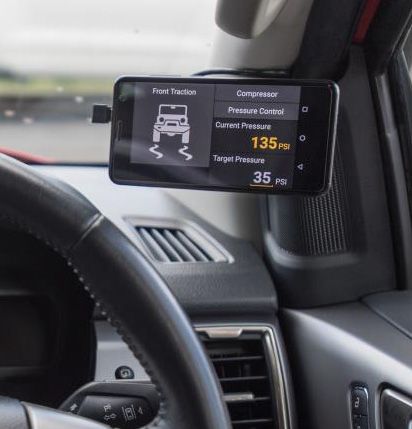
OPERATION GUIDE |   LX100 VEHICLE ACCESSORY INTERFACE KIT

                                 WHAT IS
                                  LINX?

PAGE 2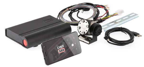
OPERATION GUIDE |           LX100 VEHICLE ACCESSORY INTERFACE KIT

WHAT IS
LINX?
LINX is a sleek touchscreen interface that enables total control of
both new and existing 4X4 Accessories. Gone are the days where
the only option for installing aftermarket switches meant drilling
multiple holes into the dashboard.

INTRODUCING TOTAL CONTROL
LINX is a unique modern controller that declutters the dashboard and centralises the command of vehicle accessories by
replacing classic switches, gauges and monitors with one sleek and smart driver interface. Built on an expandable platform,
LINX will continue to evolve your on and off road driving experience both now and into the future.

The mobile touchscreen display integrates seamlessly into the vehicle cabin and mounts to a magnetic gimbal that’s
installed within easy reach of the driver. This connects to the LINX Controller which is the brains behind the system, and is
conveniently installed out-of-sight either underneath the dash or the seat.

                                               STAY IN THE LOOP
                      For the latest details, updates and list of accessories, head over to:
                                              www.linx.arb.com.au

PAGE 3
OPERATION GUIDE |         LX100 VEHICLE ACCESSORY INTERFACE KIT

TABLE OF
CONTENTS
Get to know the basic in’s and out’s of your brand new LINX -
the next generation of 4x4 Accessories.

                                   KIT CONTENTS
01.      WHAT’S IN THE BOX?                                       p.7

                                      OVERVIEW
02.      COMPATIBLE ARB ACCESSORIES                               p.9
03.      OPTIONAL ACCESSORIES                                     p.10

                                   INITIAL SETUP
04.      SETTING UP YOUR LINX                                     p.13
05.      GETTING STARTED                                          p.14
         SWITCHING ON/OFF                                         p.15
         UPDATING LINX SOFTWARE                                   p.16
         BLUETOOTH PAIRING THE DISPLAY WITH CONTROLLER            p.18

                                  OPERATING LINX
06.      LINX DISPLAY                                             p.21
07.      HOME SCREEN                                              p.22
08.      SETTINGS MENUS                                           p.24
         QUICK SETTINGS MENU                                      p.24
         MAIN SETTINGS MENU                                       p.24
09.      LINX USER INTERFACE                                      p.25
         LINX DISPLAY SCREENS                                     p.26
10.      LINX MAIN ICON SCREEN                                    p.27
         ACCESSING EACH MODULE                                    p.28
         RETURNING TO LINX MAIN ICON SCREEN                       p.28
         LINX SETTINGS SCREEN                                     p.29
11.      UPDATING LINX                                            p.30

                                 MODULES OVERVIEW
12.      FRONT AND REAR TRACTION MODULES                          p.32
         CONFIGURING TRACTION MODULES: AIR LOCKER SETUP           p.33
13.      COMPRESSOR MODULE                                        p.35
         SWITCHING ON COMPRESSOR                                  p.35
         CONFIGURING COMPRESSOR MODULE                            p.36
         CONFIGURING PRESSURE CONTROL                             p.36
         PRESSURE CONTROL MODE LIST                               p.38

PAGE 4
OPERATION GUIDE |         LX100 VEHICLE ACCESSORY INTERFACE KIT

14.      SWITCHBOARD MODULE                                       p.40
         CONFIGURING SWITCHBOARD MODULE                           p.40
         SWITCHING ON/OFF AN ACCESSORY                            p.46
15.      BATTERY MODULE                                           p.48
         CONFIGURING BATTERY MODULE                               p.48
         BATTERY MONITORING IN FULLSCREEN                         p.52
16.      SPEEDOMETER MODULE                                       p.53
         CONFIGURING SPEEDOMETER                                  p.53
         SETTING SPEED LIMIT WARNING                              p.54
17.      AIR SUSPENSION MODULE                                    p.55
         CONFIGURING AIR SUSPENSION                               p.55
         RENAMING MODES                                           p.57
         ADJUSTING AIR PRESSURE                                   p.58
         AUTO ADJUST WITH VEHICLE START                           p.58
18.      INCLINOMETER MODULE                                      p.59
         CONFIGURING THE INCLINOMETER                             p.60
19.      CLOCK MODULE                                             p.61
20.      FRIDGE MODULE                                            p.63
         CONNECTING TO THE FRIDGE                                 p.63
         CONFIGURING FRIDGES WITH TWO WAY COMMUNICTION            p.65
         FRIDGE MONITORING IN FULLSCREEN                          p.67
21.      TPMS MODULE                                              p.68
         CONNECTING TO THE LINX TPMS COMMS BOX                    p.68
         SENSOR POSITION PROGRAMMING                              p.69
         CONFIGURING TPMS ALERTS                                  p.71
         TPMS DISPLAY                                             p.72
         AUTOMATIC TRAILER DETECTION                              p.74

                           COMPLIANCE INFORMATION
22.      COMPLIANCE INFORMATION                                   p.76
         EUROPE - EU DECLARATION OF CONFORMITY                    p.76
         USA - FCC STATEMENT                                      p.77
         ENVIRONMENTAL PROTECTION                                 p.77

PAGE 5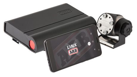
OPERATION GUIDE |   LX100 VEHICLE ACCESSORY INTERFACE KIT

                    KIT CONTENTS
                      Each and every component to get your new LINX up and
                                           running.

                                  BACK TO TABLE OF C ON T EN TS

PAGE 6
OPERATION GUIDE |             LX100 VEHICLE ACCESSORY INTERFACE KIT

01.
WHAT’S IN
THE BOX?
Congratulations on the purchase of your brand new LINX. Inside the
box, you’ll find each of the components required to get the system
up and running for your next 4x4 adventure.

                          05 WIRING LOOMS (x3)

                                                                                              06 DIN RAIL 180MM
           01
           LINX CONTROLLER

                                                             03 LINX DISPLAY
                                                                GIMBAL MOUNT
                                                                                                                    USB CABLE 04
        02 LINX DISPLAY

    NOTES
    •     The LINX Display 02 was specifically designed to withstand the extremes of heat and cold. It has a metal coupling on the

          back to connect it to the magnets on the LINX Display Gimbal Mount 03 .

    •     The LINX Controller 01   and wiring looms 05 are normally mounted under the dash, however this may vary depending on

          the vehicle.

    •     The DIN rail 06 comes assembled to the back of the LINX controller 01     and is used for securing the unit.

    •     The USB connection can be used to power and charge the LINX Display, and provide the communications channel between the
          LINX Controller and LINX Display.
PAGE 7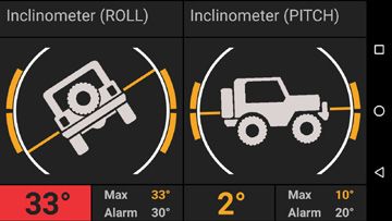
OPERATION GUIDE |   LX100 VEHICLE ACCESSORY INTERFACE KIT

                          OVERVIEW
                    Out of the box, LINX offers total control of six pre-installed
                     modules: Front & Rear Traction, Compressor & Pressure
                    Control, Battery Monitoring, Speedometer, Air Suspension
                              Control and an Accessory Switchboard.

                                  BACK TO TABLE OF C ON T EN TS

PAGE 8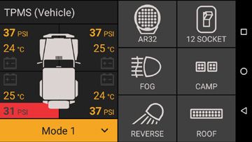
OPERATION GUIDE |            LX100 VEHICLE ACCESSORY INTERFACE KIT

02.
COMPATIBLE ARB
ACCESSORIES
There’s a range of ARB accessories that can be
controlled and monitored by LINX.

                   ARB DRIVING LIGHTS                                               AIR LOCKERS

ARB offers a large range of LED, HID and Halogen driving         Designed and manufactured in Australia, ARB Air
lights and light bars to suit your every driving need.           Lockers will enhance the traction of your 4×4 in just
Designed to perform in the most extreme conditions,              about any terrain, whether it’s rock, clay, gravel, sand,
they’ll keep the road ahead brightly lit and the rear visible    snow or mud.
wherever you go.

            ARB DUAL BATTERY SYSTEMS                                         ARB AIR COMPRESSORS

Allowing you to power additional accessories without the         ARB Air Compressors provide many advantages;
risk of flattening the main battery, an ARB Dual Battery         including inflating tyres and camping accessories,
System also provides peace of mind in the event of a main        running air tools, activating Air Lockers and even re-
battery failure.                                                 seating a tyre onto a wheel.

PAGE 9
OPERATION GUIDE |            LX100 VEHICLE ACCESSORY INTERFACE KIT

03.
OPTIONAL
ACCESSORIES
A range of products are available to complement the
LINX Vehicle Accessory Interface.

Please refer to the LINX Installation Guide or your
nearest ARB Store or Stockist for further information.

     FIND YO U R NE A R E ST STOR E

               A-PILLAR BRACKET

LINX A-Pillar Brackets are designed to provide a vehicle
specific mount that puts the LINX Display in safe and easy
reach of the driver. They are available for a large range of
popular 4WD vehicles.

PAGE 10
OPERATION GUIDE | LX100 VEHICLE ACCESSORY INTERFACE KIT
PRESSURE CONTROL KIT RELAY KIT
(7450107) (180422)
Offering ‘set & forget’ simplicity to either tyre inflation or A pre-wired relay base used for connecting
remote control over your air suspension, the optional LINX accessories that don’t come with a relay in its wiring
Pressure Control Kit (coupled with an ARB air compressor) loom. Most ARB wiring looms already come with a
allows you to take full advantage of LINX’s Pressure relay.
Control Module.
Note: Separate pressure control kits are required for tyre
inflation and air suspension.
AIR SUSPENSION ISOLATION KIT LINX TERMINAL KIT
(7450109) (7450105)
Adding an Air Suspension Isolation Kit allows owners with LINX already comes with a packet of terminals,
air suspension to take full advantage of LINX’s Air Suspen- enough to do a complete install. This kit is if you
sion Module, providing the ability to independently adjust require any extra terminals.
the pressure and ride height in each air bag.
PAGE 11OPERATION GUIDE | LX100 VEHICLE ACCESSORY INTERFACE KIT
INITIAL
SETUP
It’s time to get your LINX device up and running!
B ACK TO TABLE OF C ON T EN TS
PAGE 12OPERATION GUIDE | LX100 VEHICLE ACCESSORY INTERFACE KIT
0 4.
SETTING UP
YOUR LINX
The time taken to connect and configure accessories such as compressor, Air
Lockers and driving lights will vary depending on whether the accessory was
fitted before or after your next LINX installation. LINX is fully customisable to suit
your vehicle, please contact your local ARB distributor to discuss your individual
requirements and provide a quote for your installation.
LINX SETUP PROCESS
• Mounting of the LINX Controller.
• Connection of the power loom to the LINX Controller.
• Updating LINX software.
• Connection of 4 input wires from accessory power, parker/low beam headlamps, high beam headlamps and reverse
lamp to the LINX Controller.
• Installation of the LINX Display Gimbal Mount and/or optional vehicle specific LINX A-Pillar Bracket.
• Connection of the USB cable from the LINX Controller or optional USB power source to the LINX Display.
PAGE 13OPERATION GUIDE | LX100 VEHICLE ACCESSORY INTERFACE KIT
05.
GETTING
STARTED
The LINX Display receives power from the LINX Controller via the
USB charge cable provided.
The LINX Display’s on-board battery will take around 1 hour to fully charge from
flat condition and provide approximately 4 hours of non-connected run time. It
is normal practice to leave the display on all the time and connected when in
the vehicle. When outside the vehicle, the display communicates with the LINX
Controller via a Bluetooth connection up to 10m away.
03 LINX CONTROLLER LINX DISPLAY
01
06 POWER BUTTON
07 VOLUME
05 CLIP ON COVER 02 LINX DISPLAY
GIMBAL MOUNT
04 USB CABLE
PAGE 14OPERATION GUIDE | LX100 VEHICLE ACCESSORY INTERFACE KIT
SWITCHING ON/OFF
To switch on the Display, press & hold the power button 06 for approximately two
(2) seconds.
With the unit powered on, you can increase or decrease the volume by pressing the
volume buttons 07
To switch off the Display, press & hold the power button then tap Power off then OK.
07 VOLUME 06 POWER BUTTON
BUTTONS
For more information on installing the LINX system and associated equipment
on your vehicle, please refer to the LINX Installation Guide and your nearest ARB
outlet.
PAGE 15OPERATION GUIDE | LX100 VEHICLE ACCESSORY INTERFACE KIT
UPDATING LINX SOFTWARE
Once the LINX Controller has been connected to power it is important to check for
and perform a LINX software update before doing any further wiring.
To do this, you will need to turn on the LINX Display, connect to the internet (via
wifi for mobile data) and then connect to the LINX Controller using the provided
USB cable.
The LINX Display may take up to 1 minute to turn on and start the LINX App. When it
starts you may briefly see the ‘connecting screen’ shown below.
When the LINX Display and LINX Controller
are connected, the display should
change to ‘split screen mode’, displaying
Speedometer module and Battery module
which are activated by default.
Swipe from left to right across the screen to show the
LINX Main Icon Screen. Then tap on the settings icon.
The settings page will be displayed. Tap
LINX Update.
PAGE 16OPERATION GUIDE | LX100 VEHICLE ACCESSORY INTERFACE KIT
1. Upon selecting LINX Update the screen will display:
2. If a new version is available, tap Down-
load and follow the instructions to install.
When LINX re-connects after the update, it will determine if the LINX Controller
firmware also needs to be updated and show the following screen. Tap Update
Now and follow the instructions.
PAGE 17OPERATION GUIDE | LX100 VEHICLE ACCESSORY INTERFACE KIT BLUETOOTH PAIRING THE DISPLAY WITH CONTROLLER The LINX Display and LINX Controller can communicate using either the USB or Bluetooth connection. But before Bluetooth communication can be used, first they have to be paired. AUTO PAIRING The easiest way to pair the display and controller is to first connect them via USB and perform a software update as described in the section above. Then simply unplug the USB cable and when the LINX Display will request permission to pair, as shown below. Tap PAIR to accept the pairing. The LINX Display and LINX Controller are now paired and will connect via Bluetooth whenever in range. Note: Once the LINX Display and LINX Controller have been Bluetooth paired, the LINX Controller will become invisible to all other Bluetooth devices. The LINX Controller Bluetooth visibility can only be reset by resetting the LINX Controller, by disconnecting/reconnecting it to power. MANUAL PAIRING If the LINX system installation is already complete and USB cable hasn’t been used to connect the LINX Display and LINX Controller, and the LINX Controller is difficult to access, then the display and controller can be manually paired via the Bluetooth settings. PAGE 18
OPERATION GUIDE |          LX100 VEHICLE ACCESSORY INTERFACE KIT

Access the BLUETOOTH SETTINGS by:

1. Open up the APP DRAWER

                                                                   2. Tap SETTINGS and select BLUETOOTH

To pair with LINX:

1. Tap ‘ARB LINX’ from the available devices.

                                                                   2. Once paired, the LINX Display should
                                                                   change to ‘split screen mode’, and be dis-
                                                                   playing the vehicle’s battery voltage

PAGE 19
OPERATION GUIDE | LX100 VEHICLE ACCESSORY INTERFACE KIT
OPERATING
LINX
Learn how to navigate your LINX device.
B ACK TO TABLE OF C ON T EN TS
PAGE 20OPERATION GUIDE | LX100 VEHICLE ACCESSORY INTERFACE KIT
06.
LINX
DISPLAY
The LINX Display is the user interface that enables the driver to
access and customise the settings that control the 4X4 equipment
installed on the vehicle and connected to the LINX Controller.
It uses a capacitive touch screen and is based on the Android 6.0 operating system.
It has been designed to withstand the rigor of 4x4 driving including operating
temperatures from -20°C to 80°C.
The LINX Display supports USB, Bluetooth, WiFi and GPS connectivity and complies
with FCC, CE and RCM certifications.
07 POWER
06 VOLUME
09 SPEAKER
05 CAMERA
04 MICRO USB
PORT
08 MICROPHONE
03 AUDIO JACK
DISPLAY SCREEN 01
02 LIGHT SENSOR
PAGE 21OPERATION GUIDE | LX100 VEHICLE ACCESSORY INTERFACE KIT
07.
HOME
SCREEN
Upon start-up, the LINX Display shows the ARB LINX home screen
and then enters 'split screen mode'.
The status bar contains several icons positioned across the top of the display
which indicate the status of the unit. Items which are active/on are bright. Items
which are inactive/off are greyed out.
Settings that should remain on all the time include GPS (for the LINX
Speedometer module to operate), Bluetooth (for LINX Controller communications
when the LINX Display is disconnected from the USB cable) and WiFi as this is
used by the LINX Display to communicate with the Internet during LINX updates.
SD CARD 04
(none)
03 WIFI BATTERY 05
(on)
(full)
02 BLUETOOTH
(on)
01 GPS TIME 06
(on)
PAGE 22OPERATION GUIDE | LX100 VEHICLE ACCESSORY INTERFACE KIT
10 APP DRAWER LINX HOME 08
09 BACK RECENT 07
(Tap twice to return to Home Screen)
NOTES
• Tap Recent 07 to display a list of recently selected Apps. Scroll up/down and tap an item to return to it. To remove an item from the
list tap the X button for that item.
• Tap APP drawer 10 to display all Apps installed on your LINX Display.
• Tap LINX home 08 to return to the LINX home screen.
• Tap Back 09 to return to the previous screen. (When in LINX 'split screen mode', tap and hold to save the current module
view as Favourite. To show the Favourite view at any time, tap Back 09 again.
PAGE 23OPERATION GUIDE | LX100 VEHICLE ACCESSORY INTERFACE KIT 08. SETTINGS MENUS QUICK SETTINGS MENU Quick Settings is used to change frequently accessed items. With two fingers, swipe down from the top of the screen to open the Quick Settings menu. To toggle something on or of, simply tap the appropriate icon. MAIN SETTINGS MENU The Main Settings menu is used to control core Android settings. To open, tap the settings icon at the top right of the Quick Settings menu. Alternatively, from the Home Screen, tap App drawer, then tap Settings from the list. Swipe up or down to view setting options. Tap an item to select it. Tap Back to return to the previous menu, or Home to return to the LINX home screen. PAGE 24
OPERATION GUIDE |           LX100 VEHICLE ACCESSORY INTERFACE KIT

09.
LINX USER
INTERFACE
The LINX system offers a Graphical User Interface (GUI) similar to
that found on most smart phones and tablets.

In order to fast track your use of the LINX interface, please acquaint yourself with
these basic methods of interacting with LINX.

            SINGLE TAP a module or button to select it or turn it on/off.

            DOUBLE TAP a module to toggle between full / split screen display.

            PRESS & HOLD a module for 2 second to go to its settings menu, or
            to edit an underlined value or text.

            PRESS & HOLD swithboard buttons for momentary contact switching.

            SWIPE UP/DOWN in split
            screen mode with one finger to
            scroll to the next Module.

                        SWIPE LEFT/RIGHT in 'split screen mode' to return to the LINX Main Icon Screen.

BUTTON COLOUR STATUS                 SELECTABLE             SELECTABLE        NON-SELECTABLE
                                     (but turned off)      (and turned on)       (disabled)

AUTOMATION TRIANGLE on a button
indicates a LINX automated state of the control.

THEMED COLOURED VALUE is a real-time
display, as opposed to a set value.

PAGE 25
OPERATION GUIDE | LX100 VEHICLE ACCESSORY INTERFACE KIT
LINX DISPLAY SCREENS
MAIN ICON SCREEN
SPLIT SCREEN
(independently scroll)
FULL SCREEN
TEXT ENTRY
NUMERIC ENTRY
INFORMATION SCREEN
PAGE 26OPERATION GUIDE | LX100 VEHICLE ACCESSORY INTERFACE KIT
10.
LINX MAIN
ICON SCREEN
The LINX Main Icon Screen contains a list of the software modules installed
on your LINX Display. It provides direct access to each of the LINX modules,
the LINX settings, LINX module activation and LINX system information.
A LINX MODULE
Tap to display module in 'split screen
mode'.
B LINX SETTINGS
Tap to configure the LINX the units,
theme colour, LINX update, etc.
C MODULE ACTIVATION
Tap to show which modules are
activated.
D LINX INFORMATION
Tap to display LINX system information
screen.
E CONNECTION STATUS
Indications if Bluetooth or USB is
connected.
LINX information screen contains the LINX systems software
versions and disclaimer.
C
With Module Activation selected. Tap
individual checkboxes to activate/de-
activate individual modules (remember to scroll
up to see any additional modules).
PAGE 27OPERATION GUIDE | LX100 VEHICLE ACCESSORY INTERFACE KIT
ACCESSING EACH MODULE
The LINX Display is supplied with pre-installed software modules. These provide
access to modules like: Front and Rear Traction, Compressor, Switchboard (for
lights), Battery monitor, Speedometer and Air Suspension.
Scroll down or up to see which modules are installed.
When a module is selected, the display
automatically enters 'split screen mode'.
The screen is then divided into two
columns. Each screen can then be scrolled
vertically independent of the other.
RETURNING TO LINX MAIN ICON SCREEN
Access to the LINX Main Icon Screen is gained by swiping left or right from 'split
screen mode'.
PAGE 28OPERATION GUIDE | LX100 VEHICLE ACCESSORY INTERFACE KIT
LINX SETTINGS SCREEN
The LINX system’s Auto Night Mode integrates with the vehicles headlights and enables the user to customise the display
brightness for specific driving conditions. The Units for speed, distance, temperature and pressure can also be set
individually. The interface Theme Colour may be adjusted and a LINX Update will update the LINX software to ensure the
system is running the latest version of LINX (Note: Run a LINX Update when first installed).
01 INDICATES IF INPUT IS ON/OFF 02 AUTO NIGHT MODE
03 UNITS
04 THEME COLOUR
05 LINX UPDATE
06 CONSOLE
07 CALIBRATE VEHICLE
UNITS SELECTION SCREEEN
THEME COLOUR SCREEN
NOTES
• The Vehicle Input Status area 01 will show a coloured dot next to activated input connections on the controller.
• Use the slide control on Auto Night Mode 02 to customise the brightness level of the LINX Display for a specific
driving condition. E.g. For night driving you may want to switch your low beam lights on, then adjust the brightness
down to a level you want active when the low beam lights are next in operation.
• Tap Units 03 to bring up the units menu and tap the combination of units required.
• Tap Theme Colour 04 . Press and drag or slide to match your vehicle’s instrumentation colours.
• Run a LINX Update 05 to check if you have the latest software build and features on your device.
• Tap the Console button 06 to enter configuration commands.
• Tap Calibrate Vehicle 07 then follow the instructions to calibrate the controllers orientation within the vehicle.
PAGE 29OPERATION GUIDE | LX100 VEHICLE ACCESSORY INTERFACE KIT
11.
UPDATING
LINX
The LINX system can check for new updates whenever connected
to the Internet by tapping 'LINX Update'.
1. Upon selecting LINX Update the screen will display:
2. If a new version is available, tap Down-
load and follow the instructions to install.
When LINX re-connects after the update, it will determine if the
LINX Controller firmware also needs to be updated and show the
following screen. Tap Update Now and follow the instructions.
PAGE 30OPERATION GUIDE | LX100 VEHICLE ACCESSORY INTERFACE KIT
MODULES
OVERVIEW
When you’re ready to hit the road, accessing each
module using LINX is achieved with a simple swipe
across the touchscreen display.
BACK TO TABLE OF C ON T EN TS
PAGE 31OPERATION GUIDE | LX100 VEHICLE ACCESSORY INTERFACE KIT
12.
FRONT AND REAR
TRACTION MODULES
The LINX Front Traction and Rear Traction modules are used to
control and setup the Air Lockers installed on your vehicle and
when selected will automatically turn on the air compressor where
required to engage them.
1. Double tapping the Front Traction (or Rear Traction) mod-
ule brings up 'full screen mode' for the Traction module.
2. Now in 'full screen mode'.
To engage the rear Air Locker, simply tap the button once. Tap again to switch off
the rear Air Locker.
1. Single tap on Rear Traction.
2. Rear Traction is now engaged/locked.
PAGE 32OPERATION GUIDE | LX100 VEHICLE ACCESSORY INTERFACE KIT
CONFIGURING TRACTION MODULES: AIR LOCKER SETUP
To enter settings for the Traction modules, press and hold the module. This will
show the traction settings page. Simply tap the option you wish to set. Tap again to
unset it.
1. Press and hold Front Traction
2. Front Traction settings page. Front
Axle Second is selected by default.
The Front Traction module can be setup to operate in two ways: 'front axle second',
and 'front independent of rear'.
FRONT AXLE SECOND
'Front axle second' is the default mode in which the LINX system is supplied. It
automatically greys-out the Front Traction button making it unselectable until
the Rear Traction button is made active. This is a traditional safety feature of Air
Lockers that was factory hard wired in conventional installations.
PAGE 33OPERATION GUIDE | LX100 VEHICLE ACCESSORY INTERFACE KIT FRONT INDEPENDENT OF REAR 'Front independent of rear' mode is available when Front Axle Second is deselected. It allows the front and/or rear Air Lockers to be switched on or off independently of the other at any time. EXTERNAL LOCK SWITCH INSTALLED When External Lock Switch is selected, this allows you to control the Traction mod- ule with an Air Locker dashboard switch. LINX will display the lock / unlock state of the dashboard switch and the LINX Display button will be unselectable. TRACTION LAYOUT OPTIONS When Combined is selected, both the Front and Rear Traction buttons will be com- bined onto one tile (if they are both installed). This reduces each traction button size but frees up the other half of the display for another module. PAGE 34
OPERATION GUIDE |          LX100 VEHICLE ACCESSORY INTERFACE KIT

13.
COMPRESSOR
MODULE
AND OPTIONAL PRESSURE CONTROL MODULE

The LINX Compressor module is used to configure and operate your
air compressor. 'Pressure Control' is an optional upgrade that is
used in conjunction with the LINX Pressure Control Kit (7450107) to
inflate or deflate your tyres to a target pressure.

SWITCHING ON COMPRESSOR

To switch the Compressor on, tap the button once. Tap again to switch it off.
Note: Vehicle accessory power must be on before Compressor can be turned on.

1. Single tap on Compressor button.

                                                                                2. Compressor highlighted indicates it is on.

The blue automation triangle appears in the top right corner of the Compressor button to indicate that LINX has
changed the state of the Compressor, such as the vehicles accessory power turning off, or Front Traction turning on.

PAGE 35
OPERATION GUIDE | LX100 VEHICLE ACCESSORY INTERFACE KIT
CONFIGURING COMPRESSOR MODULE
To configure the Compressor module, press and hold anywhere on the module, this
will show the compressor settings page. Tap the option you wish to set.
Tap again to unset it.
1. Press and hold anywhere on the
Compressor module.
2. Compressor settings page (Allow Only
if Engine Running is set by default)
'Allow Only if Engine Running' ensures that the
compressor will only run when the voltage is 12.8V or
more, this prevents any damage to the compressor motor
or blown fuses if the battery levels are too low to operate
it.
CONFIGURING PRESSURE CONTROL
To activate the optional Pressure Control feature, tap the Pressure Control Installed
button then set the Maximum System Pressure to set the upper limit that can be
used when inflating your items.
This must be less than the minimum limit of your compressor’s pressure switch
(e.g. For an ARB CO35 100psi pressure switch set it to 65psi, for an ARB 180901
150psi pressure switch set it to 130 psi).
1. Tap Pressure Control Installed
2. Then set the Maximum System Pressure
PAGE 36OPERATION GUIDE | LX100 VEHICLE ACCESSORY INTERFACE KIT
Turn on the Audible Alert and a chime will sound when inflation or deflation is
complete. Simply tap the On or Off buttons to turn it on or off.
Tap Back to return to 'split screen mode'. The Display will now show the Current
Pressure in the air line connected to the Pressure Control Kit, and user definable
Target Pressure.
1. To change the Target Pressure press & hold the underlined value '33' to bring
up the keypad entry.
2. Use the keypad to input the required
value, then tap the tick to set it.
PAGE 37OPERATION GUIDE | LX100 VEHICLE ACCESSORY INTERFACE KIT
PRESSURE CONTROL MODE LIST
With pressure control installed the Current Pressure and Target Pressure fields
are activated along with the Pressure Control Mode list. Tap on the dropdown list
to select from the 3 different modes.
1. Tap the 'dropdown list' to view the list of modes.
2. Tap the desired Pressure Control Mode to
select it.
PRESSURE CONTROL MODES
Pressure Off means no air flow from the compressor, but residual pressure may
still be in the air line.
Pressure Control will turn on the compressor and the Pressure Control Valve will
try to inflate/deflate to achieve the Target Pressure to a value less than or equal to
the Maximum System Pressure setting.
Pressure Max will turn on the compressor, and open the Pressure Control Valve,
thereby opening up a straight connection between the compressor and air line
which is useful when using a blow gun on the air line.
Cancel is used to back out of the menu (ie same as tapping the Back button).
PAGE 38OPERATION GUIDE | LX100 VEHICLE ACCESSORY INTERFACE KIT
NOTES
• Parameters that may be set by the user are shown underlined.
• Theme coloured parameters (e.g. Current Pressure value) are monitored by the system.
• The Maximum System Pressure will automatically override any Target Pressure entered in excess of it.
• Current Pressure is the pressure monitored by the LINX system in whatever is connected to the LINX Pressure
control Kit.
• Target Pressure is the pressure that the user may set to either inflate or deflate their tyres.
• The LINX Display uses Bluetooth to communicate with the LINX Controller and may be disconnected from the USB
cable then removed from the mount and taken outside of the vehicle to monitor and control your tyre pressures
dynamically at the side of your vehicle.
WARNING
Tyre pressures vary by manufacturer, type, vehicle load, speed and driving conditions. Over inflating your tyres can
lead to excessive tread wear and shorten their overall life expectancy. Please consult the tyre manufacturer for the
appropriate pressure settings for your tyres and driving conditions. Always remember to re-inflate your tyres to the
correct pressure immediately upon returning to sealed roads. Failure to do so could seriously affect vehicle handling
and possibly result in tyre failure
PAGE 39OPERATION GUIDE | LX100 VEHICLE ACCESSORY INTERFACE KIT
14.
SWITCHBOARD
MODULE
The LINX Switchboard module can be used to control up to six (6)
optional switched accessories connected to your LINX Controller.
Each accessory can be given a unique name (up to 16 characters) and then be
customised to switch on or off; by user input, or an one of the 'vehicle inputs':
accessory power, parker/low beam headlamps, high beam headlamps or reverse
lamp.
They can also be turned off automatically when a user defined setting for low
voltage cut out has been detected by LINX to protect your vehicle from a flat
battery. All settings are saved back to the LINX Controller and remain active 24/7
even if the LINX Display is off or is removed from the vehicle.
CONFIGURING SWITCHBOARD MODULE
1. Press and hold on an individual accessory button
to show its settings page.
2. Tap the checkbox in the right hand corner
to activate the accessory.
PAGE 40OPERATION GUIDE | LX100 VEHICLE ACCESSORY INTERFACE KIT
RENAMING ACCESSORIES
To rename 'Accessory 1' to suit your vehicle accessory setup:
1. Press and hold the underlined
text to show the keyboard.
2. Then, enter a name relating to its func-
tion and tap DONE when complete.
E.g. To setup your front flood or spot lights you could
enter 'INTENSITYS AR32'
SWITCHBOARD LAYOUT OPTIONS
There are two layout choices for the switchboard. There is a 1 x 6 button list layout,
and there is also a 2 x 3 square icon button layout.
PAGE 41OPERATION GUIDE | LX100 VEHICLE ACCESSORY INTERFACE KIT
To select between the layout options tap the List or Icon button in the setting page
of any accessory. Then the icon graphic for each accessory is selected in the each
accessorys settings page.
1. First tap the button with the icon graphic.
2. Tap the desired icon for the that
accessory. Repeat for each accessory
button.
AUTOMATING ACCESSORIES
To automate the 'INTENSITYS AR32' to turn on or off with the vehicle’s high beams,
simply tap the high beam button in the Accessory Automation menu.
1. Tap the high beam button to
select it.
2. The button will change colour when
selected.
PAGE 42OPERATION GUIDE | LX100 VEHICLE ACCESSORY INTERFACE KIT
All automation functions are user over-ridable by default. For instance LINX might
automate the 'INTENSITY AR32' to come on whenever the high beams turn on, but the
user can still switch the 'INTENSITY AR32' on and off at any time.
However in some juristrictions, when the accessory being controlled is a driving light,
it is only allowed to be turned on with high beams, in this case tap Driving Light Mode
to select it. Then in the main switchboard view, the 'INTENSITY AR32' switch toggles
between disabled and standby, where it will follow the highbeam automation.
1. Tap the Driving Light Mode button to
select it.
2. The button will change colour when
selected.
LOW BATTERY PROTECTION
To assign Low Battery Protection to switch off the 'INTENSITYS AR32' based on
Battery 1’s set Low Voltage Alarm level:
Tap the Battery 1 button to activate it.
(Refer to the section on the Battery module for
customising the battery settings and entering a
Low Voltage Alarm level)
NOTE
• In the example shown above, the Low Battery Protection on Battery 1 will ensure that the 'INTENSITYS AR32' are
switched off (even though your high beam lamps are still switched on) once the battery level drops below limit set
by Low Voltage Alarm in the Battery module settings.
PAGE 43OPERATION GUIDE | LX100 VEHICLE ACCESSORY INTERFACE KIT
VEHICLE OFF COURTESY LIGHT TIMER
The courtesy Light feature will turn on the accessory for a set period of time when
the vehicle turns off (when LINX ACC input turns off). With the timer value to 0 the
feature is inactive. To activate the courtesty light feature simply set the Vehicle Off
Courtesy Light Timer to a value greater than 0.
The Vehicle Off Courtesy Light Timer has
been set to 10 seconds. The maximum al-
lowable value is 600 seconds (10 minutes).
ALLOW ON WHEN VEHICLE OFF
By default switchboard accessorys are not allowed to be turned on, and will be
switched off, when the vehicle is turned off (when LINX ACC input is off). To allow
an accessory to be turned on at any time, tap the Allow On When Vehicle Off button
to select it.
PAGE 44OPERATION GUIDE | LX100 VEHICLE ACCESSORY INTERFACE KIT
DIMMABLE LIGHT CONFIGURATION - ARB INTENSITY SOLIS AND
BUSHRANGER VLI
Select ARB Intensity SOLIS or Bushranger VLI from the Dimmable Light Type drop
down list. A range of brightness controls can then be configured. If ARB Intensity
SOLIS is selected, then the Intensity Solis icon is auto_selected and mandated.
Fade rate sets the rate at which the brightness changes as the dimmable lights turn
ON or OFF. Sliding the slider all the way to the right selects instantly.
Single Setting allows you to set one brightness for when the lightes are turned ON
manually or by high beams. Sliding the slider all the way to the right selects full
brightness.
Multi Modes provides 4 modes, each of which the name and brightness can be
personalised.
Note: When Intensity Solis or Bushranger VLI are configured as Multi Modes, tapping
the switchboard button will show the list of modes to select from, and if no selection
is made then LINX will toggle it ON/OFF if allowed to (check the Driving Light Mode
setting).
Courtesy brightness can be set individually. This relates to the Vehicle Off Courtesy
Light Timer feature.
DRL Enable will turn on Intensity Solis whenever the vehicle ACC is ON. The DRL
brightness can also be set individually, but it is recommended that it is set to the
miniumum which will only illuminate a small ring of LEDs in the centre of Intensity
Solis.
Recalibrate Minimum Brightness adjusts the factory minimum brightness setting for
all modes.
Tap the Dimmable Light Type drop down list and select Intensity SOLIS or
Bushranger VLI button to activate it.
Tap or slide to any position on the sliders to
select the Fate Rate or Brightness.
PAGE 45OPERATION GUIDE | LX100 VEHICLE ACCESSORY INTERFACE KIT
Tap the Multi Modes button to reveal 4 brightness modes, each of which the name
and brightness can be personalised. If the vehicle is turned ON, then the dimmable
light will shine at the selected brightness in real time. When you close the settings
page the dimmable light ON/OFF state or brightness mode will be restored.
Press and hold the underlined text to edit the mode names. Tap or slide to any
position on the sliders to set the Brightness.
Tap the Enable DRL button to activate
it. Tap or slide the slider to set the DRL
brightness.
Note: DRL should only be enabled and used in accordance with all local regulations.
SWITCHING ON/OFF AN ACCESSORY
To switch the accessory on, tap the button once. Tap again to switch off.
Switchboard buttons can also used
as a momentary contact switch for an
application such as a horn or linear
actuator. To momentarily switch the
accessory on, tap and hold the button with
two fingers at the same time. Then simply
release the button to switch off.
PAGE 46OPERATION GUIDE | LX100 VEHICLE ACCESSORY INTERFACE KIT
DIMMABLE LIGHT MULTI MODES - INTENSITY SOLIS AND
BUSHRANGER VLI
When an accessory is configured as Intensity Solis with Multi Modes, the ON/OFF
behaviour is different.
When the button is tapped, the list of modes will be shown for a couple of seconds.
If a new mode is selected then Intensity Solis will change to that mode.
However if no selection is made then the button will toggle from ON to OFF, or OFF to
ON.
For example, if Intensity Solis is ON, and the button is tapped, the mode list will be
shown and if no selection is made then it will turn OFF. However if Intensity Solis is
OFF, then it will turn ON if allowed (check the Driving Light Mode setting).
1. Tap the Intensity Solis button to change brightness mode, or turn OFF.
2. Quickly tapping a different brightness
mode will change to that brightness,
otherwise if no selection is made then it
will turn OFF.
Brightness mode 2 was selected.
No selection was made before the list closed
so Intensity Solis was turned OFF.
PAGE 47OPERATION GUIDE | LX100 VEHICLE ACCESSORY INTERFACE KIT
15.
BATTERY
MODULE
The LINX Battery module can be used to monitor and display
the charge state of up to three (3) independent batteries
simultaneously.
Each battery can be given a unique name (up to 16 characters) and then be
configured to operate with your Switchboard accessory via the Switchboard
module. (Refer to the section on the Switchboard module for further details).
CONFIGURING BATTERY MODULE
1. Press and hold Battery 1 to show its settings page.
2. Activate each battery by tapping
the checkbox in the top right corner.
Note: The greyed-out checkbox indicates that Battery 1 is the battery the LINX
Controller is connected to for power. Hence it is active by default and cannot be
de-activated.
PAGE 48OPERATION GUIDE | LX100 VEHICLE ACCESSORY INTERFACE KIT
RENAMING BATTERIES
To rename 'Battery 1' to suit your vehicle accessory setup:
1. Press and hold the underlined text to show the keyboard.
2. Then, enter a name relating to its
function, then tap DONE
EXAMPLE: To setup your main vehicle battery rename
it to 'MAIN BATTERY'.
SELECTING BATTERY TYPE
Select between FLA (Flooded Lead Acid) and AGM (Absorbed Glass Mat) battery
type to enable battery charge level and predicted discharge curve in the battery
fullscreen chart.
2. The button will change colour
when selected.
PAGE 49OPERATION GUIDE | LX100 VEHICLE ACCESSORY INTERFACE KIT
LOW VOLTAGE ALARM
To set the Low Voltage Alarm level:
1. Press & hold the underlined value '11.8' in the menu to bring
up the keypad entry.
2. Then, use the keypad to input the
required value then tap the tick to set it.
A Low Voltage Alarm when triggered will highlight in RED. For example, Battery 2
(renamed to “AUX BATTERY”) has its Low Voltage Alarm level set to “11.5V” and the
batteries actual voltage is 11.2V which now highlights in RED
Tap BACK return to Battery module screen.
NOTES
• The maximum setting for Low Voltage Alarm and Display Stop Charging is 15.0V
• Parameters that may be set by the user are shown underlined (e.g. Low Voltage Alarm value).
• Higher Display Stop Charging values (e.g. 12.7) will reduce LINX power consumption when the vehicle is not used
for long periods.
• Theme coloured parameters (e.g. battery voltage 12.7v) are displayed in real time.
PAGE 50OPERATION GUIDE | LX100 VEHICLE ACCESSORY INTERFACE KIT
DISPLAY CHARGING
The LINX Controller can switch on and off the USB charging port, to maintain optimum LINX
Display battery condition and charging efficiency, reducing LINX overall power consumption.
Additionally when the vehicles battery voltage is below the the Display Stop Charging value,
the LINX Controller will switch off the USB charging port to further reduce draw on the
vehicle battery. To enable this feature:
1. Tap the Batt Saver button.
2. Then press and hold the underlined
value to set the Display Stop Charging
value.
Note: Select Always On to disable this feature, and the USB charging port will
remain always on.
PAGE 51OPERATION GUIDE | LX100 VEHICLE ACCESSORY INTERFACE KIT
BATTERY MONITORING IN FULLSCREEN
The battery module in fullscreen contains a battery voltage history graph. When
the battery type has been configured in settings, as Flooded Lead Acid (FLA) or
Absorbed Glass Mat (AGM), then the battery monitor also estimates the battery level
(state of charge) and shows a dashed line for the predicted battery discharge curve
when there is a steady load/discharge.
A BATTERY SELECTION
Tap to select from a list of installed
batteries.
B TIME SCALE
Tap to select the time scale and view 6,
12 or 24 hours worth of battery voltage
history.
C LEVEL / STATE OF CHARGE
Displays the battery level when battery
voltage is steady or under moderate
discharge.
D DISCHARGE CURVE
Dashed line show the predicted battery
discharge curve when under steady
discharge.
E LOW VOLTAGE ALARM
The Low Voltage Alarm value configure
for each battery is shown in the as the
solid horizontal white line.
Single tap anywhere on the history graph (left side of the screen) to show the
battery voltage data for that point in time.
NOTE
• It will take up to 10 minutes of steady discharge to calculate and show the battery Level and predicted discharge
curve.
PAGE 52OPERATION GUIDE | LX100 VEHICLE ACCESSORY INTERFACE KIT 16. SPEEDOMETER MODULE The LINX Speedometer module works by GPS (Global Positioning System) to show the current speed, altitude and bearing of your vehicle. The Speedometer module operates independently of tyre size or level of inflation of your tyres, thus providing better accuracy than an uncalibrated vehicle speedometer. The Speedometer module enables the user to assign a speed limit such that a warning is issued if the limit is exceeded by the driver. Greyed-out values indicate poor GPS reception. CONFIGURING SPEEDOMETER 1. Press and hold anywhere on the Speed display, to show its settings page. PAGE 53
OPERATION GUIDE |            LX100 VEHICLE ACCESSORY INTERFACE KIT

SETTING SPEED LIMIT WARNING

To set the speed limit:

1. Press & hold the underlined value ('0 km/h') next to Speed Limit Warning to
bring up the keypad entry.

                                                                                     2. Use the keypad to input the required
                                                                                     value, then select the tick to set it.

1. Tap the tick box in the top right corner to
activate the Speed Limit Warning.

                                                                                    2. Tap the BACK to return to Speedometer
                                                                                    module screen.

LINX will now monitor the vehicles’ speed and let the
driver know when the limit has been exceeded by
changing the displayed speed colour to RED.

    NOTES
    •     Parameters that may be set by the user are shown underlined (e.g. Speed Limit Warning value).
    •     Theme coloured parameters (e.g. Altitude, Bearing and Speed) are monitored by the system.
    •     The GPS in your LINX Display requires good outdoor signal reception from at least three satellites to pinpoint your
          location for accuracy of operation. Greyed-out values indicate no GPS reception and are not real time (e.g. When
          driving through a tunnel).
PAGE 54
OPERATION GUIDE | LX100 VEHICLE ACCESSORY INTERFACE KIT 17. AIR SUSPENSION MODULE The LINX Air Suspension module (when fitted with an optional compressor, airbags and LINX Pressure Control Kit 7450107) gives you the ability to control up to 4 airbags either as pairs to level the vehicle from front to rear, or independently to cater for uneven loads from one side to the other. Independent air bag control requires the optional LINX Airbag Suspension Isolation Kit (7450109). The user can customise the pressure of the airbags then save these mode settings under unique names (up to 16 characters long) to suit different towing and vehicle load conditions then at the press of a button retrieve the settings suited for the day’s journey. For example, your modes might be named 'DAILY RIDE', 'BOAT TRAILER', 'CARAVAN' or 'QUAD TRAILER' based on the vehicle loads or range of equipment you have to hook up to your vehicle. CONFIGURING AIR SUSPENSION 1. Press and hold anywhere on the Air Suspension module to show its settings page. PAGE 55
OPERATION GUIDE |            LX100 VEHICLE ACCESSORY INTERFACE KIT

There are three options that can be set for the Front and/or Rear airbags as
follows:

None will leave the Air Suspension inactive.

Joined will control them as pairs (e.g. to level the vehicle from Front to Rear).

Split will control each side of the vehicle independently of the other to compen-
sate for uneven vehicle loads.

The range of control options will be dependent on the hardware and LINX acces-
sories you have configured on your vehicle.

SET OPERATIONAL CONTROL STATE
To set the front and/or rear airbags hardware configuration:

1. Single tap on Joined or Split.

SET MINIMUM AND MAXIMUM AIRBAG OPERATING PRESSURES
1. Press & hold on the underlined values.

PAGE 56
OPERATION GUIDE |          LX100 VEHICLE ACCESSORY INTERFACE KIT

RENAMING MODES
RENAMING MODES

1. Scroll up, then press and hold 'Mode 4'.

                                                                   2. Change name as required, then tap DONE.

1. Tap the BACK button to return to Air
Suspension module screen.

                                                                    2. The screen will return to Air Suspension
                                                                    module screen.

PAGE 57
OPERATION GUIDE | LX100 VEHICLE ACCESSORY INTERFACE KIT
ADJUSTING AIR PRESSURE
1. Tap the pressure value of one or more values requiring
adjustment (tap near '5PSI'). Tap again to deselect them.
2. Tap the + button to increment and -
button to decrement the value.
Tap the value again to deselect it and it will be saved in the current mode such as
"DAILY RIDE'.
CHANGING MODES
Select from the different modes by tapping on the drop down menu.
AUTO ADJUST WITH VEHICLE START
When the vehicle is started, if it is close to level (inclinometer pitch and roll read-
ings of less than 3 deg) and stationary, then LINX will automatically check the air
susension pressures and if required re-adjust them to the current pressure setting.
For this feature to function correctly the vehicle must first be calibrated via the
LINX Settings Screen by tapping the Calibrate Vehicle button.
NOTES
• Parameters on the settings page that may be set by the user are shown underlined (e.g. the values next to Min and
Max, and the mode names).
• Refer to your airbag manufacturer’s datasheet for the recommended Min and Max operating pressures
• Disable System option is normally used by technicians when working on and installing the system.
PAGE 58OPERATION GUIDE | LX100 VEHICLE ACCESSORY INTERFACE KIT
18.
INCLINOMETER
MODULE
The LINX Inclinometer module monitors and displays the roll
and pitch of the vehicle independant of the LINX Display. The
inclinometer can be configured to sound and display and alarm to
warn you of approaching your vehicle roll or pitch limit.
For the inclinometer to function correctly the vehicle must first be calibrated via
the LINX Settings Screen by tapping the Calibrate Vehicle button.
1. Double tapping the Inclinometer (ROLL or PITCH) module
brings up 'full screen mode' for the Inclinometer module.
2. Now in 'full screen mode'.
PAGE 59OPERATION GUIDE | LX100 VEHICLE ACCESSORY INTERFACE KIT
CONFIGURING THE INCLINOMETER
To enter settings for the Inlinometer modules, press and hold the module. This will
show the Inclinometer settings page. To edit the Limit Alarm value, press and hold
the value. Simply tap the option you wish to set. Tap again to unset it.
1. Press and hold anywhere on the Inclinometer mo-
deule to show its settings page.
2. Audible Alarm and Vehicle displayed from
the rear are selected by default.
LIMIT ALARM
A Roll / Pitch Limit Alarm when triggered will highlight in RED. For example, Roll has
its Roll Limit Alarm set to 30° and the vehicles roll is at 33° which now highlights in
RED. An audible alarm will also sound if selected in the settings.
PAGE 60OPERATION GUIDE | LX100 VEHICLE ACCESSORY INTERFACE KIT
19.
CLOCK
MODULE
The LINX Clock module includes a range of time related functions
such as local and world time, date, timer, alarm, and stop watch.
The date and local time will be automatically set whenever the LINX Display is able
to receive GPS signal or a SIM card is used to connect it to a telecommunications
network. Alternatively the date and time can be manually set in the Android main
setting menu. For help finding the Android settings menu refer to section 8.
1. To access each of the Clock functions tap on the drop down
list and tap again to select.
TIMER FUNCTION
1. Tap and hold on the underlined values to set the timer.
2. With the timer set you can now tap the
Start button. When the timer has counted
down to zero an audile notification will
sound once.
PAGE 61OPERATION GUIDE | LX100 VEHICLE ACCESSORY INTERFACE KIT
ALARM FUNCTION
1. To edit the alarm time, first tap the Enable button.
2. Tap and hold the underlined value to set
the alarm time. At the alarm time an audible
alarm will sound, tap Disable to turn the alarm
off, or tap Snooze to add 9 minutes to the
alarm time.
STOP WATCH FUNCTION
1. Tap Start to begin.
2. Tap Stop to end.
WORLD TIME FUNCTION
1. Tap Change Time Zone to select from a list of timezones.
PAGE 62OPERATION GUIDE | LX100 VEHICLE ACCESSORY INTERFACE KIT
20.
FRIDGE
MODULE
The LINX Fridge module can monitor/control the ARB Zero Fridge Freezer
range and compatible ARB Classic and Elements Fridge Freezers that have
been fitted with an ARB Fridge App Connect module (ARB #10900041).
When connected to an ARB Zero Fridge or Series 2 ARB Fridge the module can be used to
monitor and control the Fridge. Series 1 ARB Fridge Freezer manufactured post 2014 allow
monitor function only.
CONNECTING TO THE FRIDGE
1. Tap and hold the Fridge module to enter settings.
2. Tap the Connect to fridge button to
search for nearby fridges.
PAGE 63OPERATION GUIDE | LX100 VEHICLE ACCESSORY INTERFACE KIT
ZERO FRIDGES
3. Tap to select 'ARB ZERO' from the list. No pin code is
required to connect.
ARB CLASSIC OR ELEMENTS FRIDGE WITH 'FRIDGE APP CONNECT MODULE'
3. Tap to select your fridge from the list. Ensure that the
name matches that printed on the underside of the Fridge
App Connect module.
4. You will then be asked to enter a security
pin code to connect to the fridge, this is
also printed on the underside of the Fridge
App Connect module.
PAGE 64OPERATION GUIDE | LX100 VEHICLE ACCESSORY INTERFACE KIT
CONFIGURING FRIDGES WITH TWO WAY COMMUNICTION
LINX auto detects which ARB fridge model it is connected to and only enables the
relevant features for that model. For example:
- ARB Classic and Elements fridges, only monitor the settings and current status.
- Series 2 ARB Classic and Elements fridges with 2 way communication, monitor the
status and also control the set temperature, Battery Protection level, Display Brightness,
set 3 temperature mode names and values. Additionally Elements lock can be controlled.
-ARB Zero Fridge, monitor status and control the set temperature, Boost mode, Battery
Protection level, set 3 temperature mode names and values.
1. To change the Battery Protection or Display Brightness on the fridge,
simply tap your selection.
2. To change the temperature mode names
and values, scroll up then press and hold the
underlined text to show the keyboard. Change
the name/value as required and then tap
DONE.
3. Tap the BACK button to return to Fridge
module screen.
4. The screen will return to Fridge module
screen.
PAGE 65OPERATION GUIDE | LX100 VEHICLE ACCESSORY INTERFACE KIT
CHANGING MODES
1. To select different temperature modes, or turn the
fridge on standby, tap the dropdown list.
2. Then tap your selection from the list to
change modes.
WARNINGS
The fridge lid open icon highlights RED when the lid is open.
If the fridge has a check status, such 'Low Battery Voltage', a pop-up
will be displayed with an explanation. Tap OK to clear the pop-up.
Tap the Check symbol to view the pop-up
message again.
PAGE 66OPERATION GUIDE | LX100 VEHICLE ACCESSORY INTERFACE KIT
FRIDGE MONITORING IN FULLSCREEN
The fridge module in fullscreen contains temperature and voltage history graphs.
The graph type is selectable from the button in the top left corner.
A GRAPH TYPE SELECTION
Tap to select between temperature and
voltage history.
B TIME SCALE
Tap to select the time scale and
view 6, 12 or 24 hours worth of fridge
temperature and voltage history.
C LIVE READING
Displays the fridges current
temperature or voltage.
D TEMPERATURE SET POINT
The set temperature is shown in the as
the solid horizontal white line.
Single tap anywhere on the history graph (left side of the screen) to show the
fridge temperature (or voltage) data for that point in time.
PAGE 67OPERATION GUIDE | LX100 VEHICLE ACCESSORY INTERFACE KIT
21.
TPMS
MODULE
The LINX TPMS module monitors ARB Air Systems TPMS sensors through
the use of the LINX TPMS Comms Box (ARB #7450116). It displays the
current tyre pressure and temperature. It sounds and displays alerts related
to pressure, temperature, sensor low battery and a non-communicating
sensor.
Once trailers have been configured LINX it will automatically switch
between them, or active/deactivate them when are are connected/
disconnected to your vehicle.
The TPMS (Vehicle) module supports 4 tyre sensors and 2 spare tyre sensors. 4 modes
can be programmed each with different names and set pressures for front and rear tyres,
accomodating the wide range of 4x4 tyre pressures that may be used in different terrain and
load conditions.
The TPMS (Trailer) module supports up to 3 different trailers each with 4 tyre sensors and 2
spare tyre sensors. Each trailer also has 4 modes that can be programmed with a single set
pressure for all tyres. Additionally each trailer can be named, configured as single or tandem
axle and an appropriate icon chosen.
A pressure alert will occur if a tyre pressure is above or below it set pressure +/- the pressure
variation alert.
The setting for temperature alert applies to all tyres, and the spare tyre set pressure applies
to all spare tyres on the vehicle and trailers.
CONNECTING TO THE LINX TPMS COMMS BOX
1. Tap and hold the TPMS module to enter settings.
2. Tap the Connect to TPMS button to
search for your TPMS Comms Box.
PAGE 68OPERATION GUIDE | LX100 VEHICLE ACCESSORY INTERFACE KIT
3. Tap to select your LINX TPMS Comms Box 'LINXTPMS 1234'
from the list.
Once connected, the option to program the
sensor positions becomes available.
SENSOR POSITION PROGRAMMING
1 vehicle and 3 trailers can be programmed with up to 4 tyre sensors and 2 spare tyre
sensors. To Learn the sensors and their positions follow the on screen text pop ups.
The sensor positions can be quickly and easily swapped if you rotate your tyres or
change to a spare tyre.
SENSOR POSITION LEARNING
1. Tap the Learn button. At first all tyre positions are
shown in light grey, indicating no tyre sensor has been
associated with this position.
2. Follow the onscreen instructions to
activate a tyre sensor and LINX TPMS will
learn the tyre sensors unique ID.
PAGE 69OPERATION GUIDE | LX100 VEHICLE ACCESSORY INTERFACE KIT
When a sensor position has been associated with a tyre
sensor the button is shown in the LINX theme colour.
Shown here all 4 vehicle tyre sensor positions have been
learned.
SENSOR POSITION SWAPPING
1. Tap the Swap button. Then tap the two sensor positions
you would like to swap.
2. Tap Confirm to complete the sensor
position swap.
PAGE 70OPERATION GUIDE | LX100 VEHICLE ACCESSORY INTERFACE KIT
SENSOR POSITION DELETE
1. Tap the Delete button. Then tap the sensor positions you
would like to delete.
2. Tap Confirm to complete the sensor
position delete.
CONFIGURING TPMS ALERTS
TPMS (VEHICLE) SETTINGS
The vehicle has 4 modes available, each of which can named and configured with
different set pressures for the front tyres and the rear tyres, accomodating the wide
range of 4x4 tyre pressures that may be used in different terrain and load conditions.
To change the alert values, pressure mode names and values, scroll up then press and
hold the underlined text to show the keyboard. Change the name/value as required and
then tap DONE.
A TEMPERATURE ALERT
Alert will occur when any tyre
temperature is above this setting.
B PRESSURE VARIATION ALERT
Alert will occur if a tyre pressure is
above or below it set pressure +/- the
pressure variation alert.
C FRONT TYRES (MODE 1)
This pressure setting applies to the
front tyres when in Mode 1.
D REAR TYRES (MODE 1)
This pressure setting applies to the rear
tyres when in Mode 1.
E MODE NAME
Note: The alert pressure is calculated using the Pressure Setting for the Customizable mode names.
current mode and the Pressure Variation Alert. Eg. In the example above the
Mode 1 Front Tyres are set to 36 PSI, an alert would occur if the tyre pressure
is below 31 PSI (= 36 - 5), or is the tyre pressure is above 41 PSI (= 36 + 5).
PAGE 71You can also read