Magnetostrictive level transmitter for hazardous areas, models FLM-CAI, FLM-TAI, BLM-TAI Magnetostriktiv-Füllstandstransmitter für ...
←
→
Page content transcription
If your browser does not render page correctly, please read the page content below
Operating instructions
                                                       Betriebsanleitung

Magnetostrictive level transmitter for hazardous areas,
                                                                                 EN
models FLM-CAI, FLM-TAI, BLM-TAI

Magnetostriktiv-Füllstandstransmitter für explosionsgefährdete
                                                                                 DE
Bereiche, Typen FLM-CAI, FLM-TAI, BLM-TAI

          Mounting flange, spherical float from stainless steel, model FLM-CAI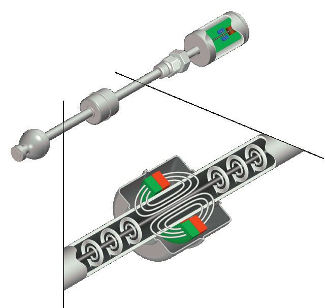
Operating instructions models FLM-CAI, FLM-TAI,                             Page              3 - 36
EN BLM-TAI (Ex)

   Betriebsanleitung Typen FLM-CAI, FLM-TAI, BLM-TAI                           Seite           37 - 70
DE (Ex)

   © 09/2019 WIKA Alexander Wiegand SE & Co. KG
   All rights reserved. / Alle Rechte vorbehalten.
   WIKA® is a registered trademark in various countries.
   WIKA® ist eine geschützte Marke in verschiedenen Ländern.

   Prior to starting any work, read the operating instructions!
                                                                                                           14392029.03 03/2021 EN/DE

   Keep for later use!

   Vor Beginn aller Arbeiten Betriebsanleitung lesen!
   Zum späteren Gebrauch aufbewahren!

    2            Operating instructions magnetostrictive level transmitter, models FLM-xAI, BLM-TAI (Ex)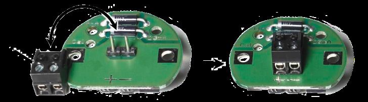
Contents

                            Contents                                                                                                              EN

                            1. General information                                                                                            5
                            2. Design and function                                                                                            5
                               2.1 Description . . . . . . . . . . . . . . . . . . . . . . . . 5
                               2.2 Model overview  .  .  .  .  .  .  .  .  .  .  .  .  .  .  .  .  .  .  .  .  .  . 6
                               2.3 Construction and principle of operation  .  .  .  .  .  .  .  .  .  .  .  .  .  . 7
                               2.4 Scope of delivery  .  .  .  .  .  .  .  .  .  .  .  .  .  .  .  .  .  .  .  .  .  . 8
                            3. Safety                                                                                                         9
                               3.1 Explanation of symbols  .  .  .  .  .  .  .  .  .  .  .  .  .  .  .  .  .  .  .  . 9
                               3.2 Intended use  .  .  .  .  .  .  .  .  .  .  .  .  .  .  .  .  .  .  .  .  .  .  . 9
                               3.3 Improper use  .   .   .   .   .   .   .   .   .   .   .   .   .   .   .   .   .   .   .   .   .   .   . 10
                               3.4 Responsibility of the operator   .   .   .   .   .   .   .   .   .   .   .   .   .   .   .   .   . 10
                               3.5 Personnel qualification  .   .   .   .   .   .   .   .   .   .   .   .   .   .   .   .   .   .   .   . 11
                               3.6 Personal protective equipment  .   .   .   .   .   .   .   .   .   .   .   .   .   .   .   .   . 11
                               3.7 Labelling, safety marks  .  .  .  .  .  .  .  .  .  .  .  .  .  .  .  .  .  .  . 12
                               3.8 Ex marking  .   .   .   .   .   .   .   .   .   .   .   .   .   .   .   .   .   .   .   .   .   .   .   . 12
                            4. Transport, packaging and storage                                                                              13
                               4.1 Transport  .   .   .   .   .   .   .   .   .   .   .   .   .   .   .   .   .   .   .   .   .   .   .   . 13
                               4.2 Packaging and storage  .  .  .  .  .  .  .  .  .  .  .  .  .  .  .  .  .  .  . 13
                            5. Commissioning, operation                                                                                      14
                               5.1 Mounting   .   .   .   .   .   .   .   .   .   .   .   .   .   .   .   .   .   .   .   .   .   .   .   . 14
                                   5.1.1 “Screw-in body” version   .   .   .   .   .   .   .   .   .   .   .   .   .   .   .   .   . 16
                                   5.1.2 “Flange” version  .   .   .   .   .   .   .   .   .   .   .   .   .   .   .   .   .   .   .   . 17
                                   5.1.3 “Mounting on bypass” version  .   .   .   .   .   .   .   .   .   .   .   .   .   .   . 17
                               5.2 Electrical connection   .   .   .   .   .   .   .   .   .   .   .   .   .   .   .   .   .   .   .   . 19
                                   5.2.1 Connection diagram (Ex)  .   .   .   .   .   .   .   .   .   .   .   .   .   .   .   .   . 19
                                   5.2.2 Cable length  .  .  .  .  .  .  .  .  .  .  .  .  .  .  .  .  .  .  .  .  . 20
                                   5.2.3 Wiring with cable gland  .  .  .  .  .  .  .  .  .  .  .  .  .  .  .  .  . 21
                                   5.2.4 Wiring with M12 connector  .   .   .   .   .   .   .   .   .   .   .   .   .   .   .   . 22
                               5.3 Adjustment .   .   .   .   .   .   .   .   .   .   .   .   .   .   .   .   .   .   .   .   .   .   .   . 24
14392029.03 03/2021 EN/DE

                                   5.3.1 Measuring span on the level transmitter  .   .   .   .   .   .   .   .   .   .   .   . 24
                                   5.3.2 Current supply in error mode  .  .  .  .  .  .  .  .  .  .  .  .  .  .  . 25
                            6. Safety-related characteristic values                                                                          26
                            7. Faults                                                                                                        28

                             Operating instructions magnetostrictive level transmitter, models FLM-xAI, BLM-TAI (Ex)                        3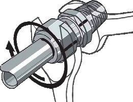
Contents

     8. Maintenance and cleaning                                                                                          30
         8.1 Maintenance  .  .  .  .  .  .  .  .  .  .  .  .  .  .  .  .  .  .  .  .  .  .  .                             30
         8.2 Cleaning  .  .  .  .  .  .  .  .  .  .  .  .  .  .  .  .  .  .  .  .  .  .  .  .                             30
EN   9. Dismounting, return and disposal                                                                                  31
         9.1 Dismounting  .  .  .  .  .  .  .  .  .  .  .  .  .  .  .  .  .  .  .  .  .  .  .                             31
         9.2 Return  .   .   .   .   .   .   .   .   .   .   .   .   .   .   .   .   .   .   .   .   .   .   .   .   .    31
         9.3 Disposal  .  .  .  .  .  .  .  .  .  .  .  .  .  .  .  .  .  .  .  .  .  .  .  .                             31
     10. Specifications                                                                                                   32
         10.1 Model FLM-CAI  .  .  .  .  .  .  .  .  .  .  .  .  .  .  .  .  .  .  .  .  .                                32
         10.2 Model FLM-TAI  .   .   .   .   .   .   .   .   .   .   .   .   .   .   .   .   .   .   .   .   .   .        33
         10.3 Model BLM-TAI  .   .   .   .   .   .   .   .   .   .   .   .   .   .   .   .   .   .   .   .   .   .        34
         10.4 Float   .   .   .   .   .   .   .   .   .   .   .   .   .   .   .   .   .   .   .   .   .   .   .   .   .   34
     Annex: EU declaration of conformity                                                                                  36

     Declarations of conformity can be found online at www.wika.com.

                                                                                                                               14392029.03 03/2021 EN/DE

      4            Operating instructions magnetostrictive level transmitter, models FLM-xAI, BLM-TAI (Ex)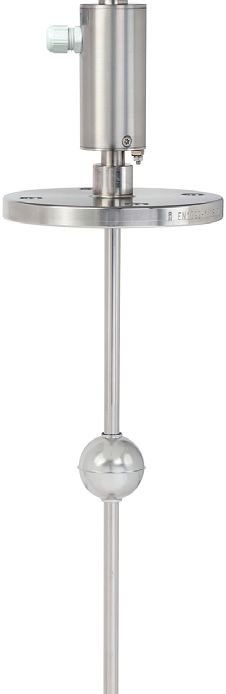
1. General information / 2. Design and function

                            1. General information
                            ■ The magnetostrictive level transmitters described in the operating instructions have
                              been designed and manufactured using state-of-the-art technology. All components
                              are subject to stringent quality and environmental criteria during production. Our             EN
                              management systems are certified to ISO 9001.
                            ■ These operating instructions contain important information on handling the instrument.
                              Working safely requires that all safety instructions and work instructions are observed.
                            ■ Observe the relevant local accident prevention regulations and general safety
                              regulations for the instrument’s range of use.
                            ■ The operating instructions are part of the product and must be kept in the immediate
                              vicinity of the instrument and readily accessible to skilled personnel at any time. Pass
                              the operating instructions on to the next operator or owner of the instrument.
                            ■ Skilled personnel must have carefully read and understood the operating instructions
                              prior to beginning any work.
                            ■ The general terms and conditions contained in the sales documentation shall apply.

                            ■ Subject to technical modifications.

                            ■ Further information:
                              - Internet address:         www.wika.de / www.wika.com
                              - Relevant data sheet:      LM 20.04 (FLM-CAI)
                                                          LM 20.01 (FLM-TAI)
                                                          LM 10.05 (BLM-TAI)

                            2. Design and function

                            2.1 Description
                            The model FLM-CAI (with guide tube Ø 6 mm) and model FLM-TAI (with guide tube
                            Ø 12 mm) high-accuracy level transmitters are used for the continuous measurement
                            of the level of liquid media in vessels. The measurement procedure used exploits the
                            physical effect of magnetostriction and is largely independent of the temperature. It is used,
                            especially, where very precise level measurements are required, such as in the chemical
                            industry.
14392029.03 03/2021 EN/DE

                            In these operating instructions, the FLM is described with cable connection on the side of
                            the probe head. As cable connection, an M12 cable gland (also with M16 adapter), an M12
                            connector or an M20 or ½ NPT female thread are possible. As a further variant, there is
                            an FLM with an M12 connector on the probe head cover. Model BLM-TAI can be used for
                            mounting to bypass chambers.

                             Operating instructions magnetostrictive level transmitter, models FLM-xAI, BLM-TAI (Ex)     5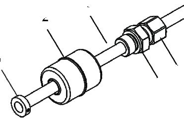
2. Design and function

     The level transmitter emits a 4 … 20 mA output signal, which is configured via buttons
     within the probe head, or a digital output signal as HART® protocol.

     Probe lengths of 100 mm to 6 m, as “Flex version” up to 10 m, and also various
     temperature and pressure ranges are possible.
EN
     Available versions:
     ■ With screw-in body, welded or for step-free positioning
     ■ With flange process connection
     ■ For mounting on a bypass with magnetic float
     ■ With 90° angled probe head
     ■ With 6 mm guide tube
     ■ With 6 mm guide tube and short cable bushing
     ■ With 12 mm guide tube

     This level transmitter with ATEX and IECEx approval can be installed in hazardous areas
     that require electrical equipment of equipment protection level Ga (zone 0), equipment
     protection level Ga/Gb (zone 0/1) or equipment protection level Gb (zone 1).

     The instrument is designed in accordance with the following European standards:
     EN IEC 60079‑0:2018 Equipment – General requirements
     EN 60079‑11:2012       Device protection through intrinsic safety “i“
     EN 60079‑26:2015       Equipment of equipment protection level (EPL) Ga

     2.2   Model overview

      Model             Guide tube diameter in mm                       Installation type
      FLM-CAI           6                                               Direct installation
      FLM-TAI           12                                              Direct installation
      BLM-TAI           12                                              Bypass mounting
                                                                                                          14392029.03 03/2021 EN/DE

      6         Operating instructions magnetostrictive level transmitter, models FLM-xAI, BLM-TAI (Ex)
2. Design and function
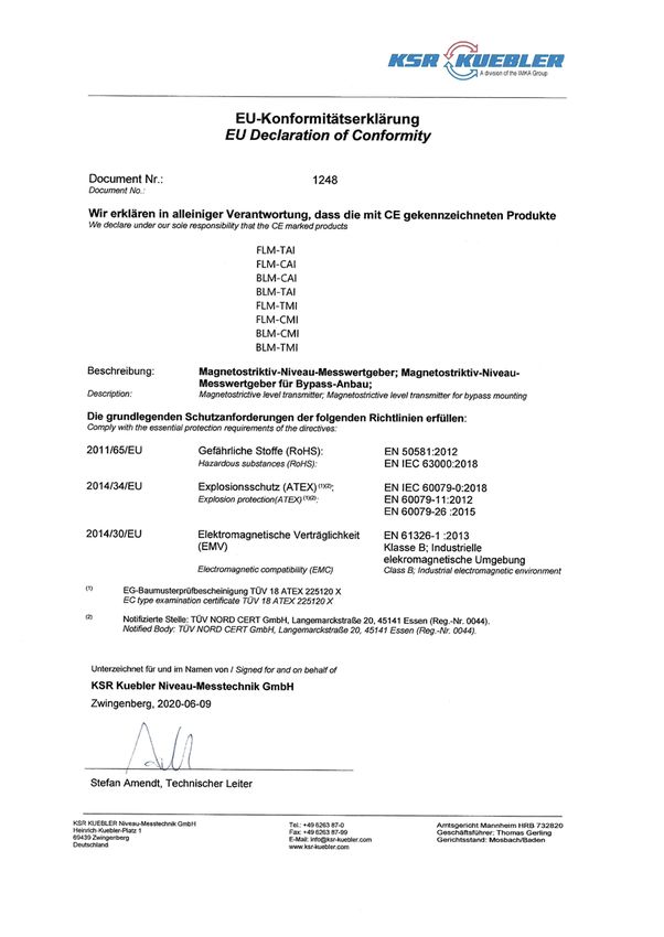
2.3 Construction and principle of operation
The construction of the level transmitter is illustrated in the version with screw-in body. In
the probe head of the level transmitter are located the connection terminals and the
adjustment buttons protected by the cover . The electrical connection is made via an
M16 x 1.5 cable gland or M12 plug connection on the top of the probe head and the
ground connection at the bottom of the probe head (see chapter 5.1 “Mounting” and 5.3
EN
“Adjustment”).
On the guide tube , for highly-adjustable mounting in the vessel, there is a screw-in
body (compression fitting) or, for fixed mounting, a flange (not shown). The float is
used for the continuous measurement of the product filling height or interface layer and is
held on the guide tube by an adjusting collar .
The “BLM for bypass mounting” version is delivered without process connection and float.
14392029.03 03/2021 EN/DE
Operating instructions magnetostrictive level transmitter, models FLM-xAI, BLM-TAI (Ex) 72. Design and function
The measurement procedure shown in the following figure exploits the physical effect of
magnetostriction and is largely independent of the temperature. In the guide tube, a wire
from magnetostrictive material is stretched. Via the sensor electronics, current pulses
are sent through the wire, which generate a circular magnetic field . A magnet , which
is built into the float, acts as the level pick-up. Its magnetic field magnetises the wire axially.
EN Through the interference of the two magnetic fields, in the area of the float magnet, a
torsion wave is generated, which runs in both directions along the wire. One wave runs
directly to the probe head, the other is reflected off the lower end of the guide tube. The
time between the sending of the current pulse and the arrival of the wave at the probe head
is measured. From the time elapsed, the float position is determined.
2.4 Scope of delivery
Cross-check scope of delivery with delivery note.
14392029.03 03/2021 EN/DE
8 Operating instructions magnetostrictive level transmitter, models FLM-xAI, BLM-TAI (Ex)3. Safety
3. Safety
3.1 Explanation of symbols
DANGER!
... indicates a directly dangerous situation resulting in serious injury or death, if
EN
not avoided.
WARNING!
... indicates a potentially dangerous situation that can result in serious injury or
death, if not avoided.
CAUTION!
... indicates a potentially dangerous situation that can result in light injuries or
damage to property or the environment, if not avoided.
DANGER!
... indicates a potentially dangerous situation in the hazardous area that can
result in serious injury or death, if not avoided.
Information
... points out useful tips, recommendations and information for efficient and
trouble-free operation.
3.2 Intended use
Magnetostrictive level transmitters are used exclusively for the continuous measurement of
the level of liquid media in vessels.
The level transmitters are designed as intrinsically safe equipment and are suitable for use
in hazardous areas. All level transmitters can be used for all gases of group IIA, IIB and IIC.
In addition, all level transmitters may be used for the dust groups IIIA, IIIB and IIIC.
If a non-conductive plastic float is to be used in hazardous areas with gases of group IIC,
the danger due to static charging must be prevented. Observe the following conditions:
■ The float must not be used in strongly flowing, non-conductive liquids.
■ There must be no stirrer in the tank.
■ Frictions on non-conductive components must be avoided.
■ The float must not be cleaned dry.
14392029.03 03/2021 EN/DE
Operating instructions magnetostrictive level transmitter, models FLM-xAI, BLM-TAI (Ex) 93. Safety
The instrument has been designed and built solely for the intended use described here,
and may only be used accordingly.
The manufacturer shall not be liable for claims of any type based on operation contrary to
the intended use.
EN
3.3 Improper use
Improper use is defined as any application that exceeds the technical performance limits.
WARNING!
Injuries through improper use
Improper use of the instrument can lead to hazardous situations and injuries.
▶ Refrain from unauthorised modifications to the instrument.
Any use beyond or different to the intended use is considered as improper use.
Do not use this instrument in safety or emergency stop devices.
3.4 Responsibility of the operator
The instrument is used in the industrial sector. The operator is therefore responsible for
legal obligations regarding safety at work.
The safety instructions within these operating instructions, as well as the safety, accident
prevention and environmental protection regulations for the application area must be
maintained.
To ensure safe working on the instrument, the operating company must ensure:
■ that suitable first-aid equipment is available and aid is provided whenever required.
■ that the operating personnel are regularly instructed in all topics regarding work safety,
first aid and environmental protection and know the operating instructions and, in
particular, the safety instructions contained therein.
■ that the instrument is suitable for the particular application in accordance with its
intended use.
14392029.03 03/2021 EN/DE
10 Operating instructions magnetostrictive level transmitter, models FLM-xAI, BLM-TAI (Ex)3. Safety
3.5 Personnel qualification
WARNING!
Risk of injury should qualification be insufficient
Improper handling can result in considerable injury and damage to property.
▶ The activities described in these operating instructions may only be carried EN
out by skilled personnel who have the qualifications described below.
Skilled personnel
Skilled personnel, authorised by the operator, are understood to be personnel who, based
on their technical training, knowledge of measurement and control technology and on
their experience and knowledge of country-specific regulations, current standards and
directives, are capable of carrying out the work described and independently recognising
potential hazards.
Special knowledge for working with instruments for hazardous areas:
The skilled personnel must have knowledge of ignition protection types, regulations and
provisions for equipment in hazardous areas.
Special operating conditions require further appropriate knowledge, e.g. of aggressive
media.
3.6 Personal protective equipment
The personal protective equipment is designed to protect the skilled personnel from
hazards that could impair their safety or health during work. When carrying out the various
tasks on and with the instrument, the skilled personnel must wear personal protective
equipment.
Follow the instructions displayed in the work area regarding personal protective
equipment!
The requisite personal protective equipment must be provided by the operating company.
14392029.03 03/2021 EN/DE
Operating instructions magnetostrictive level transmitter, models FLM-xAI, BLM-TAI (Ex) 11Ser. No.:
Art. No.:
3. Safety Tag. No.: 4 ... 20 mA
IP68 max. DC 15 ... 30 V
3.7 Labelling, safety marks WIKA Alexander Wiegand SE & Co. KG
Alexander-Wiegand-Strasse 30
63911 Klingenberg
Product label
EN Level Sensor ???????
Type: ???-????????????????
????????????????
0637
Bj.:????
Ui=3. Safety / 4. Transport, packaging and storage
ATEX
IECEx
II 1G Ex ia IIC T6 ... T4 Ga
II 1/2G Ex ia IIC T6 ... T4 Ga/Gb
II 2G Ex ia IIC T6 ... T4 Gb EN
II 1D Ex ia IIIC T160 °C Da
Special conditions for use (X conditions)
1. When using titanium floats, the risk of ignition due to impact or friction shall be avoided.
2. When using plastic floats, there is a danger of ignition due to electrostatic discharge.
4. Transport, packaging and storage
4.1 Transport
Check the instrument for any damage that may have been caused by transport.
Obvious damage must be reported immediately.
CAUTION!
Damage through improper transport
With improper transport, a high level of damage to property can occur.
▶ When unloading packed goods upon delivery as well as during internal
transport, proceed carefully and observe the symbols on the packaging.
▶ With internal transport, observe the instructions in chapter 5.2 “Packaging
and storage”.
4.2 Packaging and storage
Do not remove packaging until just before mounting.
Keep the packaging as it will provide optimum protection during transport (e.g. change in
installation site, sending for repair).
14392029.03 03/2021 EN/DE
Operating instructions magnetostrictive level transmitter, models FLM-xAI, BLM-TAI (Ex) 135. Commissioning, operation
5. Commissioning, operation
DANGER!
Danger to life from explosion!
EN Through working in flammable atmospheres, there is a risk of explosion which
can cause death.
▶ Only carry out set-up work in non-hazardous environments!
DANGER!
Risk of injury due to improper use
Work on containers involves the danger of intoxication and suffocation.
▶ No work is allowed to be carried out unless by taking suitable personal
protective measures (e.g. breathing apparatus, protective clothing etc.).
▶ Work on the instrument must only be carried out by trained skilled
personnel.
5.1 Mounting
Screw-in body Flange Mounting on bypass
112
112
116
Probe head
Probe head
Neck tube
Screw-in
88
body
Flange
Guide tube length
Guide tube length
Guide tube
Guide tube
Insertion length
14392029.03 03/2021 EN/DE
Float
Float
Adjusting Adjusting
collar collar
14 Operating instructions magnetostrictive level transmitter, models FLM-xAI, BLM-TAI (Ex)5. Commissioning, operation
■ During mounting, ensure that the guide tube is not bent and that the float is not
subjected to shock loads.
■ The installation of the level transmitter in areas with strong external magnetic fields is
not permitted, since this will impede the correct measured value determination.
■ The level transmitter can also be installed in the vessel from below. If the vessel is also
pressurised, then the maximum length of the level transmitter is 2 m.
EN
■ If, during mounting, the float is removed, it must be slid back onto the guide tube with
the marking “TOP” in the direction of the probe head, so that correct measurement can
be made.
Information for safe mounting
The mounting should only be carried out in an unpowered state!
Prior to installation, it may be necessary to remove the float(s). When assembling, make
sure that the float(s) is/are mounted in the correct position on the sensor tube.
Only the sensor head of the ...LM-...I model with screw terminals should be opened.
Information for safe installation
The installation should only be carried out in an unpowered state. Observe special
regulations, e.g. EN 60079-14 or the local installation regulations.
If the level transmitter is supplied with a screw-in body, the thread of the screw-in body
must be provided with suitable sealing material, screwed into the existing bushing and
tightened. If the level transmitter is supplied without process connection, the operator is
responsible for compliance with the Ex requirements.
General note (see also EN 60079‑26, section 4.3)
If the level transmitter is installed in the separating wall between zone 0 and zone 1, a
sufficiently tight gap (IP66 or IP67) must be ensured after installation.
The process connection may cause an opening in the separating wall to the area requiring
EPL “Ga“. There is then a risk of flammable gases being released and flames breaking
through.
14392029.03 03/2021 EN/DE
Operating instructions magnetostrictive level transmitter, models FLM-xAI, BLM-TAI (Ex) 155. Commissioning, operation
5.1.1 “Screw-in body” version
EN
The dismounting of the float is then only required if the float cannot pass
through the mounting hole in the vessel. Otherwise, only mounting steps 3, 6
and, if necessary, 7 must be carried out.
Inserting the level transmitter into the vessel:
1. Loosen both threaded pins, remove the adjusting collar and remove the float from
the guide tube .
2. If necessary, slide the screw-in body onto the guide tube.
3. Insert the level transmitter into the vessel, apply suitable sealing material to, screw in
and tighten the mounting thread .
4. Slide the float back onto the guide tube .
The float must be slid back onto the guide tube with the marking “TOP” in the
direction of the probe head, so that correct measurement can be made.
5. Re-affix the adjusting collar , position and secure the threaded pins over the groove.
6. Position the process connection to its height and tighten the union nut finger-tight by
hand.
7. Secure the union nut with a spanner through a 1 ¼ turn (see following figure).
Securing the compression fitting
14392029.03 03/2021 EN/DE
16 Operating instructions magnetostrictive level transmitter, models FLM-xAI, BLM-TAI (Ex)5. Commissioning, operation
5.1.2 “Flange” version
The guide tube is firmly welded to the flange, so the insertion length cannot be changed.
Secure the flange and the flange sealing with the flange screws and nuts. The screws, nuts
and seals are the responsibility of the operator and should be chosen dependent upon the
measuring medium. The fixing equipment and sealings must fulfil the requirements of the
EN
EN 1092-1, EN 1514 and EN 1515 standards.
Should the float be unable to pass through the mounting hole, see mounting instructions,
chapter 5.1.1 ““Screw-in body” version”.
5.1.3 “Mounting on bypass” version
The level transmitter is mounted on the outside of the bypass tube with suitable mounting
material (non-magnetic) (see following figure).
To ensure a reliable measurement, the guide tube must be mounted free of
tension, without external deformations.
▶ The distance between guide tube and bypass tube must be as slow as possible.
▶ Only floats approved by us can be used.
14392029.03 03/2021 EN/DE
Operating instructions magnetostrictive level transmitter, models FLM-xAI, BLM-TAI (Ex) 175. Commissioning, operation
Mounting with bypass
BLM for bypass
Distance from guide tube to centre of float:
max. distance depending on bypass float
EN
min. magnet
position
Guide tube,
mounted free
of tension (not
deformed)
Measuring range
Guide tube length
Bypass tube
Magnet position
min. magnet
position
Bypass float
14392029.03 03/2021 EN/DE
Probe fixing
(un-magnetic)
Section A-A
Spacer
18 Operating instructions magnetostrictive level transmitter, models FLM-xAI, BLM-TAI (Ex)5. Commissioning, operation
5.2 Electrical connection
5.2.1 Connection diagram (Ex)
Buffer amplifier (example)
EN
Wiring resistance
Supply voltage
Prior to starting operation, please check all instruments for proper connection and
installation. Check the electrical supply, also of the connected instruments.
Voltage source Umax = DC 30 V
Minimum supply voltage Umin = 8 V
Overall resistance (incl. wiring resistance and load) ΣR = (U - Umin) / 0.0215 A
In hazardous areas, the intrinsically safe version of the level transmitter may only be
connected to buffer amplifiers that are certified by a notified body and whose electrical
output data meet the following criteria:
U0 ≤ 30 V
I0 ≤ 100 mA / 200 mA 1)
P0 ≤ 1 W
▶ For further data, see the EC-type examination certificate at www.wika.com.
1) The permissible input current li depends on the ambient temperature Ta.
Make sure that the permissible external capacitance C0 and inductance L0 of the buffer
amplifier are not exceeded if the level transmitter is used in a hazardous environment (see
chapter 6 “Safety-related characteristic values”).
The connection cable to the buffer amplifier must be marked in case of applications in a
hazardous environment - preferably as a blue cable for intrinsically safe circuits.
▶ Connection of the cable, see chapter 5.2.3 “Wiring with cable gland” and 5.2.4 “Wiring
with M12 connector”)
14392029.03 03/2021 EN/DE
According to the dielectric strength requirements of EN 60079-11, section 6.3.13, there is
compliance with the insulation test between the intrinsically safe circuit and the chassis of
the level transmitter with a voltage of AC 500 V.
Operating instructions magnetostrictive level transmitter, models FLM-xAI, BLM-TAI (Ex) 195. Commissioning, operation
5.2.2 Cable length
The maximum cable length is dependent upon the overall resistance, which is composed
of the wiring resistance and the load of connected instruments (see chapter 5.2.1
“Connection diagram (Ex)”).
EN The cable (length and cross-section) must be selected such that, in the event of the
highest current supply (21.5 mA), the voltage does not drop below the probe-specific
minimum supply voltage (8 V).
Make sure that, when used in hazardous areas, the permissible external capacitance C0
and inductance L0 of the associated equipment are not exceeded (see chapter 6 “Safety-
related characteristic values”).
Maximum overall resistance with different supply voltages and also cable resistances at
different cross-sections:
Supply Max. overall Cable cross- Cable resistance per m
voltage in V resistance in Ω section in mm² of copper cable in Ω/m
12 (-5 %) 158 0.5 0.0356
1.0 0.0178
1.5 0.0119
24 (-5 %) 688 0.5 0.0356
1.0 0.0178
1.5 0.0119
The maximum cable length is calculated as follows:
L = Cable length in m
U = Supply voltage V (with negative tolerance value -5 %)
Umin = Minimum supply voltage V = 8 V
Imax = highest current supply A = 0.0215 A
RB = Load
RQ = Cable resistance of copper cable (per m) in Ω/m with cable cross-section Q in mm²
14392029.03 03/2021 EN/DE
20 Operating instructions magnetostrictive level transmitter, models FLM-xAI, BLM-TAI (Ex)5. Commissioning, operation
Example:
Supply voltage: 12 V (±5 %)
Supply voltage U = 11.4 V (12 V - 5 %)
Minimum supply voltage Umin = 8 V
Highest current supply Imax = 0.0215 A
Load RB = 86.8 Ω
EN
Cable resistance RQ = 0.0356 Ω/m with cable cross-section Q = 0.5 mm²
A cable with a forward and return line (2-wire) can therefore be a maximum of 1,000 m
long.
5.2.3 Wiring with cable gland
The wiring should only be carried out in the unpowered state.
Carry out the wiring of the level transmitter as follows:
1. Unscrew the probe head cover using an open-ended spanner.
2. Loosen the union nut of the cable gland .
14392029.03 03/2021 EN/DE
Operating instructions magnetostrictive level transmitter, models FLM-xAI, BLM-TAI (Ex) 215. Commissioning, operation
Removable screw terminal
EN
3. Thread the 2-wire cable into the union nut and tighten (outer diameter: 5 … 10 mm).
4. Remove the screw terminal .
5. Connect the 2-wire cable to the poles marked with (+) and (–) on the screw terminal .
6. Re-affix the screw terminal . The cable must not have any tension!
7. If required, set reference points (see chapter 5.3.1 “Measuring span on the level
transmitter”).
8. Screw the probe head cover back down.
The ground connection on the underside of the probe head can be used for grounding or
equipotential bonding.
CAUTION!
Damage due to incorrect mounting
The probe head and the electronics can be damaged through ingress of water.
▶ Protect the probe head against water ingress. A safe sealing of the cable
entry is guaranteed with an outer cable diameter of 5 ... 10 mm.
▶ Screw the cable gland and probe head cover tight.
5.2.4 Wiring with M12 connector
The wiring should only be carried out in the unpowered state.
If not yet connected, plug the coupling of the connection cable onto the M12 connector
of the probe head. First turn the M12 connector till it is hand-tight and then secure the nut
with a 180° turn using an open-ended spanner. The tightening torque should be between
100 ... 150 cNm.
14392029.03 03/2021 EN/DE
22 Operating instructions magnetostrictive level transmitter, models FLM-xAI, BLM-TAI (Ex)5. Commissioning, operation
For the level transmitters with screw terminals, model …LM‑…AI, the terminal designation
is “+“ and “-“. For the level transmitters with M12 connector, the pin assignments are as
follows:
Signal Colour coding Assignment
EN
Voltage + Brown Pin 1
Pin 3
Not in use White Pin 2 Pin 4
Voltage - Blue Pin 3
Not in use Black Pin 4
Pin 2 Pin 1
Pin assignment of the coupling of the WIKA connection cable
Characteristic for connection cable between level transmitter and associated equipment:
■ 2-wire, non-shielded cable
■ Blue or marked in blue (cable for intrinsically safe circuits)
The grounding or the equipotential bonding must be carried out by the installer in
accordance with the applicable national installation regulations. The ground connection of
the probe head can be used for the grounding or the equipotential bonding. Please also
observe the general installation regulations.
The sensors must be integrated into the equipotential bonding of the hazardous area. For
the integration of the level transmitters into the equipotential bonding, the sensor head is
equipped with a PA connection terminal.
General note (see also EN 60079‑14:2014, section 6.4.1)
Bodies of electrical equipment do not have to be separately connected to the equipotential
bonding system if they have firm and secured metallic contact with structural components
or pipelines which are, in turn, connected to the equipotential bonding system.
14392029.03 03/2021 EN/DE
Operating instructions magnetostrictive level transmitter, models FLM-xAI, BLM-TAI (Ex) 235. Commissioning, operation
5.3 Adjustment
For variants with HART® protocol, the settings described in the following can also be made
conveniently remotely without having to open the probe head.
5.3.1 Measuring span on the level transmitter
EN For the adjustment of the 4 mA and 20 mA points on the level transmitter, there are two
buttons ( and ) and a light-emitting diode (LED) in the connection area of the probe
head.
Maximum measuring span (factory-set):
4 mA at the probe foot and 20 mA at the probe head
The measuring span can be set individually for adjustment to the respective vessel.
Minimum distance of 10 mm must not be breached! If this minimum distance is breached,
the display direction of the level transmitter reverses automatically (empty quantity
measurement).
Through the adjustment, the specification of the measured value can also be inverted, e.g.
the level transmitter can be set with a maximum measuring span with 4 mA at the probe
head and 20 mA at the probe foot.
Adjustment of the measuring span
14392029.03 03/2021 EN/DE
1. Unscrew the probe head cover using an open-ended spanner.
2. Hold down the 4 mA button or 20 mA button for a period of at least 3 seconds. The
green LED starts to blink.
24 Operating instructions magnetostrictive level transmitter, models FLM-xAI, BLM-TAI (Ex)5. Commissioning, operation
3. The level transmitter enters adjustment mode. The current supply of the level transmitter
is 12 mA. Without pressing the button again, the level transmitter remains in adjustment
mode for 20 seconds before it switches back to measuring mode without changing the
adjustment. In adjustment mode, the 4 mA and the 20 mA reference point or both can
now be changed in any order.
4. Define a reference point: Move float to the desired reference point and
EN
■ press the “4 mA” button briefly (0.1 … 2 seconds), in order to define a current
supply of 4 mA at this position.
■ press the “20 mA” button briefly (0.1 … 2 seconds), in order to define a current
supply of 20 mA at this position.
After pressing the “4 mA” button, the LED goes out for 5 seconds, after
pressing the “20 mA” button, the LED lights up for 5 seconds continuously.
Subsequently, the sensor remains for a further 15 seconds in adjustment
mode before saving the change and reverting to measuring mode.
The adjustment of the measuring range is only saved when the level
transmitter automatically changes from adjustment mode to measuring mode
and the LED goes out. The adjustment is retained even if the level transmitter
is subsequently disconnected from the power supply.
In order to be able to make the setting “dry” for bypass sensors, the manufacturer of the
bypass requires a magnetic system with spacer. The adjustment can then also be carried
out on the dismounted sensor.
5.3.2 Current supply in error mode
If the level transmitter cannot detect a meaningful float position (i.e. a correct level) due to a
fault, it switches to an error mode after a short time. The signalisation in error mode conforms
to NAMUR NE43 and is factory-set to 21.5 mA - it can, however, be set to 3.6 mA.
To adjust the current supply in the error mode, see figure page 24.
1. Unscrew the probe head cover using an open-ended spanner.
2. Hold down both the “4 mA” button and the “20 mA” button simultaneously for a
period of at least 3 seconds.
The green LED “Cal/Err” blinks rapidly. The current supply of the level transmitter
is 16 mA. After 5 seconds the LED no longer blinks and displays the set error current
supply for 2.5 seconds. If the LED is permanently lit, IError = 21.5 mA, if the LED goes
out, IError = 3.6 mA. Without pressing the button again, the level transmitter remains in
error mode for another 2.5 seconds before it would switch back to measuring mode
14392029.03 03/2021 EN/DE
without changing the setting.
Operating instructions magnetostrictive level transmitter, models FLM-xAI, BLM-TAI (Ex) 255. Commissioning ... / 6. Safety-related characteristic values
3. To set a current supply
■ of 3.6 mA, during the dwell time (10 seconds) in error mode, press the “4 mA” button
briefly (0.1 ... 2 seconds).
■ of 21.5 mA, during the dwell time (10 seconds) in error mode, press the “20 mA”
button briefly (0.1 ... 2 seconds).
EN
The adjustment of the measuring range is only saved when the level
transmitter automatically changes from adjustment mode to measuring mode
and the LED goes out. The adjustment is retained even if the level transmitter
is subsequently disconnected from the power supply.
4. Screw the probe head cover back down.
If the level transmitter detects, during operation, that a correct output of the level is not
possible due to a too low supply voltage, it switches to error mode and sets the current
supply to 3.6 mA (independent of the error current settings made).
6. Safety-related characteristic values
For the connection of the level transmitter to a certified intrinsically safe circuit, the
following maximum values apply:
Ui = 30 V
Ii = 100 mA / 200 mA 1)
Pi = 1 W
Li = 20 µH
Ci = 10 nF
1) The permissible input current li depends on the ambient temperature Ta.
14392029.03 03/2021 EN/DE
26 Operating instructions magnetostrictive level transmitter, models FLM-xAI, BLM-TAI (Ex)6. Safety-related characteristic values
The maximum temperatures for use in gas hazardous areas, depending on the
temperature class and the category or equipment protection level, are indicated in
temperature table 1:
Temperature table 1: Operating temperatures of the level transmitters
EN
Temperature class Ta Tf
Category 1G or equipment protection level Ga (complete level transmitter installed in zone 0)
T6 Ii ≤ 100 mA: -20 … +40 °C
Ii ≤ 200 mA: -20 … +25 °C
T5 Ii ≤ 100 mA: -20 … +55 °C
Ii ≤ 200 mA: -20 … +40 °C
T4, T3, T2, T1 -20 … +60 °C
Category 1/2G or equipment protection level Ga/Gb (sensor head installed in zone 1,
sensor tube installed in zone 0)
T6 Ii ≤ 100 mA: -40 … +55 °C Ii ≤ 100 mA: -20 … +40 °C
Ii ≤ 200 mA: -40 … +40 °C Ii ≤ 200 mA: -20 … +25 °C
T5 Ii ≤ 100 mA: -40 … +55 °C Ii ≤ 100 mA: -20 … +55 °C
Ii ≤ 200 mA: -40 … +40 °C Ii ≤ 200 mA: -20 … +40 °C
T4, T3, T2, T1 Ii ≤ 100 mA: -40 … +85 °C -20 … +60 °C
Ii ≤ 200 mA: -40 … +70 °C
Category 2G or equipment protection level Gb (complete level transmitter installed in zone 1)
T6 Ii ≤ 100 mA: -40 … +40 °C -40 ... +85 °C
Ii ≤ 200 mA: -40 … +25 °C
T5 Ii ≤ 100 mA: -40 … +55 °C -40 ... +100 °C
Ii ≤ 200 mA: -40 … +40 °C
T4 Ii ≤ 100 mA: -40 … +85 °C -40 ... +135 °C
Ii ≤ 200 mA: -40 … +70 °C
T3 -40 ... +200 °C
T2 -40 ... +300 °C
T1 -40 ... +450 °C
For use in category 1G or 1/2G the following applies:
The process pressure of the media must be between 0.8 bar and 1.1 bar in the presence
of explosive vapour/air mixtures. If no explosive mixtures are present, the instruments may
also be operated outside this range in accordance with the manufacturer's specifications.
Appropriate measures must be taken to ensure that the temperature (Ta) of the respective
14392029.03 03/2021 EN/DE
temperature class is not exceeded at any point of the sensor head.
Operating instructions magnetostrictive level transmitter, models FLM-xAI, BLM-TAI (Ex) 276. Safety-related characteristic values / 7. Faults
General note (see also EN IEC 60079‑0, section 1)
Zone 0 is only given under atmospheric conditions
Temperature range: ‑20 … +60 °C
Pressure range: 0.8 … 1.1 bar
EN Oxidising agents: Air (oxygen content approx. 21 %)
The maximum ambient temperatures for use in gas hazardous areas, depending on the
surface ambient temperature and the dust layer, are indicated in temperature table 2.
Temperature table 2: Operating temperatures for dust hazardous areas
Maximum surface temperature Ambient temperature Ta
Dust layer ≤ 5 mm With dust cover
Ta + 75 °C Observe EN 60079-14 -40 … +85 °C
7. Faults
DANGER!
Danger to life from explosion
Through working in flammable atmospheres, there is a risk of explosion which
can cause death.
▶ Only rectify faults in non-flammable atmospheres!
CAUTION!
Physical injuries and damage to property and the environment
If faults cannot be eliminated by means of the listed measures, the instrument
must be taken out of operation immediately.
▶ Ensure that there is no longer any pressure present and protect against
being put into operation accidentally.
▶ Contact the manufacturer.
▶ If a return is needed, please follow the instructions given in chapter 9.2
“Return”.
For contact details see chapter 1 “General information” or the back page of the
operating instructions.
14392029.03 03/2021 EN/DE
28 Operating instructions magnetostrictive level transmitter, models FLM-xAI, BLM-TAI (Ex)7. Faults
The following table contains the most frequent causes of faults and the necessary
countermeasures.
Faults Causes Measures
No or undefined function Incorrect terminal assignment Compare connection diagram EN
Insulation not clamped sufficiently Check the terminals
Adjusting collar has slipped or is Check the location of the
incorrectly fitted after the removal adjusting collar
from the guide tube
False 0 ... 100 % values Incorrectly fitted float Turn the float
Incorrect details with the order Contact the manufacturer
Defective wave guide through Return to the manufacturer
mechanical effects
Incorrectly adjusted Readjust or contact
manufacturer
The transmitter cannot be Thread sizes and flange sizes for Modification of the vessel
mounted at the planned the level transmitter and vessel do or modification of the level
place on the vessel not match transmitter in the factory
Thread on the screwed coupling at Rework the thread or replace
the vessel defective the screwed coupling
Mounting thread at the level Return to the manufacturer
transmitter defective
14392029.03 03/2021 EN/DE
Operating instructions magnetostrictive level transmitter, models FLM-xAI, BLM-TAI (Ex) 298. Maintenance and cleaning
8. Maintenance and cleaning
For contact details see chapter 1 “General information” or the back page of the
operating instructions.
EN
8.1 Maintenance
When used properly, the magnetostrictive level transmitters work maintenance-free. They
must be subjected to visual inspection within the context of regular maintenance, however,
and included in the vessel pressure test.
DANGER!
Risk of injury due to improper use
Work on containers involves the danger of intoxication and suffocation.
▶ No work is allowed to be carried out unless by taking suitable personal
protective measures (e.g. breathing apparatus, protective clothing etc.).
▶ Work on the instrument must only be carried out by trained skilled
personnel.
Repairs must only be carried out by the manufacturer.
Perfect functioning of the magnetostrictive level transmitters can only be
guaranteed when original accessories and spare parts are used.
8.2 Cleaning
CAUTION!
Physical injuries and damage to property and the environment
Improper cleaning may lead to physical injuries and damage to property and
the environment. Residual media in the dismounted instrument can result in a
risk to persons, the environment and equipment.
▶ Rinse or clean the dismounted instrument.
▶ Take sufficient precautionary measures.
1. Prior to cleaning, properly disconnect the instrument from the process and the power
supply.
2. Clean the instrument carefully with a moist cloth.
Electrical connections must not come into contact with moisture!
CAUTION!
14392029.03 03/2021 EN/DE
Damage to property
Improper cleaning may lead to damage to the instrument!
▶ Do not use any aggressive cleaning agents.
▶ Do not use any hard or pointed objects for cleaning.
3. Wash or clean the dismounted instrument, in order to protect persons and the
environment from exposure to residual media.
30 Operating instructions magnetostrictive level transmitter, models FLM-xAI, BLM-TAI (Ex)9. Dismounting, return and disposal
9. Dismounting, return and disposal
WARNING!
Physical injuries and damage to property and the environment through
residual media EN
Residual media in the dismounted instrument can result in a risk to persons,
the environment and equipment.
▶ Wash or clean the dismounted instrument, in order to protect persons and
the environment from exposure to residual media.
9.1 Dismounting
Only disconnect the measuring instrument once the system has been depressurised and
the power disconnected!
Only the sensor head of the ...LM-...I model with screw terminals should be opened.
Further dismounting would possibly damage the level transmitter and invalidate the
approval.
9.2 Return
Before returning, an approval is required through our customer service. To do
this, contact the customer advisor or customer service, who will inform you
about the details of the return.
Wash or clean the dismounted magnetostrictive level transmitter before returning it, in
order to protect personnel and the environment from exposure to residual media.
Information on returns can be found under the heading “Service” on our local
website.
9.3 Disposal
Incorrect disposal can put the environment at risk.
Dispose of instrument components and packaging materials in an environmentally
compatible way and in accordance with the country-specific waste disposal regulations.
14392029.03 03/2021 EN/DE
Operating instructions magnetostrictive level transmitter, models FLM-xAI, BLM-TAI (Ex) 3110. Specifications
10. Specifications
10.1 Model FLM-CAI
Magnetostrictive level transmitter
EN
Guide tube ■ Ø 6 mm (max. 1,000 mm)
■ Ø 12 mm (max. 3,000 mm)
Process connection Mounting thread downwards
■ G 1/2 ... G 2
■ 1/2 NPT ... 2 NPT
Mounting flange
■ ANSI 1/2" ... 2 1/2", class 150 ... 600
■ EN DN 20 ... DN 65, PN 6 ... PN 100
■ DIN DN 20 ... DN 65, PN 6 ... PN 100
Other process connections on request
Materials
Wetted parts Stainless steel 1.4571 (316Ti)
Connection head Stainless steel 1.4305 (303)
Insertion length
Guide tube Ø 6 mm 100 ... 1,000 mm
Guide tube Ø 12 mm 100 … 3,000 mm
Measurement accuracy ±1.25 mm
Resolution 0.1 mm
Electrical connection Connection terminals max. 1.5 mm²
Supply voltage DC 8 ... 30 V
Output signal ■ 4 ... 20 mA (NAMUR NE43)
■ HART® ver. 6
Vibration resistant version (option) to 4 g (only for guide tube Ø 12 mm)
Operating pressure Depending on the float, max. 40 bar
Operating temperature
Guide tube Ø 6 mm -40 ... +125 °C
Guide tube Ø 12 mm -40 ... +250 °C
Ambient temperature -40 ... +85 °C
Ingress protection per EN 60529 IP68
Configuration
14392029.03 03/2021 EN/DE
Version without HART® protocol Via two built-in buttons in the connection housing
Version with HART® protocol Via two built-in buttons, HART® communicator or
HART® interface in the connection housing
For further specifications see data sheet LM 20.04 and the order documentation.
32 Operating instructions magnetostrictive level transmitter, models FLM-xAI, BLM-TAI (Ex)10. Specifications
10.2 Model FLM-TAI
Mounting thread Flange
Electrical connection Sensor housing, material stainless steel 1.4301
Process connection Mounting thread downwards Mounting flange EN
G 1 1/2 or G 2 ■ DIN DN 50 ... DN 200,
PN 6 ... PN 100
■ ANSI 2" ... 8", class 150 ... 600
Max. guide tube length L
Guide tube Ø 12 mm 3,000 mm
Guide tube Ø 18 mm 6,000 mm
Float Material: Stainless steel 1.4571 (option: Titanium)
Float diameter from 44 ... 120 mm
Float selection depending on guide tube Ø and process
conditions (see data sheet LM 20.01, page 8 / 9)
Max. operating pressure 40 bar (100 bar with float from titanium)
→ see data sheet LM 20.01, table on page 8
Temperature range
Medium (standard)
High-temperature version -45 ... +450 °C
Low-temperature version -90 ... +125 °C
Ambient temperature -40 ... +85 °C
Output signal 4 ... 20 mA, HART®
Supply voltage DC 10 ... 30 V
Measurement accuracy < ±0.5 mm
Resolution < 0.1 mm
Load max. 900 Ω at 30 V
Mounting position Vertical ±30°
Ingress protection IP68 per IEC/EN 60529
For further specifications see data sheet LM 20.01 and the order documentation.
14392029.03 03/2021 EN/DE
Operating instructions magnetostrictive level transmitter, models FLM-xAI, BLM-TAI (Ex) 3310. Specifications
10.3 Model BLM-TAI
Specifications
Connection housing (sensor Stainless steel 1.4305, optionally stainless steel 1.4404
housing)
EN
Sensor tube Stainless steel 1.4571, optionally stainless steel 1.4404
Tube Ø 12 mm, tube length L max. 6,000 mm
Medium temperature -60 ... +450 °C
Ambient temperature T4/T5/T6: -40 ... +85/+55/+40 °C
Output signal 4 ... 20 mA, HART®
Supply voltage DC 10 ... 30 V
Measurement accuracy < ±0.5 mm
Resolution < 0.1 mm
Ingress protection IP68
For further specifications see data sheet LM 10.05 and the order documentation.
10.4 Float
The float is an essential component of the level transmitter, which must be matched to the
medium in terms of density, pressure strength and material resistance.
The floats listed below are interchangeable and can be reordered individually. Further float
models and materials are available on request.
▶ The density and magnet position of floats of the same type vary slightly, so that
readjustment may be necessary.
▶ All floats can also be used with a pressure of -1 bar (vacuum).
Material Version Description For guide tube Limit density
Ø in mm 85 % in kg/m3
Stainless steel V18/42A Cylinder Ø 18 mm 6 800
1.4571 (316Ti)
V27A Cylinder Ø 27 mm 6 700
V29A Sphere Ø 29 mm 6 920
V29A/40 Cylinder Ø 29 mm 12 620
14392029.03 03/2021 EN/DE
V44A Cylinder Ø 44 mm 12 720
V52A Sphere Ø 52 mm 12 690
Titanium 3.7035 T29A Sphere Ø 29 mm 6 700
(grade 2)
34 Operating instructions magnetostrictive level transmitter, models FLM-xAI, BLM-TAI (Ex)10. Specifications
Material Version Description For guide tube Limit density
Ø in mm 85 % in kg/m3
Buna (NBR) B20A Cylinder Ø 20 mm 6 940
B23A Cylinder Ø 23 mm 6 800
EN
B25A Cylinder Ø 25 mm 6 790
B30A Cylinder Ø 30 mm 6 680
B40A Cylinder Ø 40 mm 12 580
The pressure strength can only be ensured for undamaged floats. Even the
smallest and invisible dents, for example when the float falls from the table
onto a stone floor, are sufficient to significantly reduce the pressure strength.
14392029.03 03/2021 EN/DE
Operating instructions magnetostrictive level transmitter, models FLM-xAI, BLM-TAI (Ex) 35Annex: EU declaration of conformity
EN
14392029.03 03/2021 EN/DE
36 Operating instructions magnetostrictive level transmitter, models FLM-xAI, BLM-TAI (Ex)Inhalt
Inhalt
1. Allgemeines 39 DE
2. Aufbau und Funktion 39
2.1 Beschreibung . . . . . . . . . . . . . . . . . . . . . . . 39
2.2 Typenübersicht . . . . . . . . . . . . . . . . . . . . . . 40
2.3 Aufbau und Funktionsweise . . . . . . . . . . . . . . . . . . 41
2.4 Lieferumfang . . . . . . . . . . . . . . . . . . . . . . . 42
3. Sicherheit 43
3.1 Symbolerklärung . . . . . . . . . . . . . . . . . . . . . . 43
3.2 Bestimmungsgemäße Verwendung . . . . . . . . . . . . . . . 43
3.3 Fehlgebrauch . . . . . . . . . . . . . . . . . . . . . . . 44
3.4 Verantwortung des Betreibers . . . . . . . . . . . . . . . . . 44
3.5 Personalqualifikation . . . . . . . . . . . . . . . . . . . . 45
3.6 Persönliche Schutzausrüstung . . . . . . . . . . . . . . . . . 45
3.7 Beschilderung, Sicherheitskennzeichnungen . . . . . . . . . . . . 46
3.8 Ex-Kennzeichnung . . . . . . . . . . . . . . . . . . . . . 46
4. Transport, Verpackung und Lagerung 47
4.1 Transport . . . . . . . . . . . . . . . . . . . . . . . . 47
4.2 Verpackung und Lagerung . . . . . . . . . . . . . . . . . . 47
5. Inbetriebnahme, Betrieb 48
5.1 Montage . . . . . . . . . . . . . . . . . . . . . . . . 48
5.1.1 Ausführung „Einschraubkörper“ . . . . . . . . . . . . . . . 50
5.1.2 Ausführung „Flansch“ . . . . . . . . . . . . . . . . . . 51
5.1.3 Ausführung „Anbau an Bypass“ . . . . . . . . . . . . . . . 51
5.2 Elektrischer Anschluss . . . . . . . . . . . . . . . . . . . . 53
5.2.1 Anschlussplan (Ex) . . . . . . . . . . . . . . . . . . . 53
5.2.2 Kabellänge . . . . . . . . . . . . . . . . . . . . . 54
5.2.3 Verdrahtung bei Kabelverschraubung . . . . . . . . . . . . 55
5.2.4 Verdrahtung bei M12-Stecker . . . . . . . . . . . . . . . 56
5.3 Justierung . . . . . . . . . . . . . . . . . . . . . . . . 58
14392029.03 03/2021 EN/DE
5.3.1 Messbereichsspanne am Füllstandstransmitter . . . . . . . . . 58
5.3.2 Stromaufnahme im Fehlermodus . . . . . . . . . . . . . . 59
6. Sicherheitstechnische Kennwerte 60
7. Störungen 62
Betriebsanleitung Magnetostriktiv-Füllstandstransmitter, Typen FLM-xAI, BLM-TAI (Ex) 37Inhalt
8. Wartung und Reinigung 64
8.1 Wartung . . . . . . . . . . . . . . . . . . . . . . . . . 64
8.2 Reinigung . . . . . . . . . . . . . . . . . . . . . . . . 64
9. Demontage, Rücksendung und Entsorgung 65
9.1 Demontage . . . . . . . . . . . . . . . . . . . . . . . 65
9.2 Rücksendung . . . . . . . . . . . . . . . . . . . . . . . 65
DE 9.3 Entsorgung . . . . . . . . . . . . . . . . . . . . . . . 65
10. Technische Daten 66
10.1 Typ FLM-CAI . . . . . . . . . . . . . . . . . . . . . . 66
10.2 Typ FLM-TAI . . . . . . . . . . . . . . . . . . . . . . . 67
10.3 Typ BLM-TAI . . . . . . . . . . . . . . . . . . . . . . . 68
10.4 Schwimmer . . . . . . . . . . . . . . . . . . . . . . . 68
Anlage: EU-Konformitätserklärung 70
Konformitätserklärungen finden Sie online unter www.wika.de.
14392029.03 03/2021 EN/DE
38 Betriebsanleitung Magnetostriktiv-Füllstandstransmitter, Typen FLM-xAI, BLM-TAI (Ex)1. Allgemeines / 2. Aufbau und Funktion
1. Allgemeines
■ Die in der Betriebsanleitung beschriebenen Magnetostriktiv-Füllstandstransmitter
werden nach dem aktuellen Stand der Technik konstruiert und gefertigt. Alle Komponen-
ten unterliegen während der Fertigung strengen Qualitäts- und Umweltkriterien. Unsere
Managementsysteme sind nach ISO 9001 zertifiziert.
■ Diese Betriebsanleitung gibt wichtige Hinweise zum Umgang mit dem Gerät. Voraus-
setzung für sicheres Arbeiten ist die Einhaltung aller angegebenen Sicherheitshinweise DE
und Handlungsanweisungen.
■ Die für den Einsatzbereich des Gerätes geltenden örtlichen Unfallverhütungsvorschrif-
ten und allgemeinen Sicherheitsbestimmungen einhalten.
■ Die Betriebsanleitung ist Produktbestandteil und muss in unmittelbarer Nähe des
Gerätes für das Fachpersonal jederzeit zugänglich aufbewahrt werden. Betriebsanlei-
tung an nachfolgende Benutzer oder Besitzer des Gerätes weitergeben.
■ Das Fachpersonal muss die Betriebsanleitung vor Beginn aller Arbeiten sorgfältig
durchgelesen und verstanden haben.
■ Es gelten die allgemeinen Geschäftsbedingungen in den Verkaufsunterlagen.
■ Technische Änderungen vorbehalten.
■ Weitere Informationen:
- Internet-Adresse: www.wika.de / www.wika.com
- Zugehöriges Datenblatt: LM 20.04 (FLM-CAI)
LM 20.01 (FLM-TAI)
LM 10.05 (BLM-TAI)
2. Aufbau und Funktion
2.1 Beschreibung
Die hochgenauen Füllstandstransmitter Typen FLM-CAI (mit Gleitrohr-Ø 6 mm) und
FLM-TAI (mit Gleitrohr-Ø 12 mm) dienen zur kontinuierlichen Füllstandsmessung von
flüssigen Medien in Behältern. Das angewandte Messverfahren nutzt den physikalischen
Effekt der Magnetostriktion aus und ist weitgehend unabhängig von der Temperatur. Es
findet besonders dort Anwendung, wo sehr exakte Füllstandsmessungen erforderlich sind,
wie z. B. in der chemischen Industrie.
14392029.03 03/2021 EN/DE
In dieser Betriebsanleitung ist der FLM mit Kabelanschluss seitlich am Sonden-
kopf beschrieben. Als Kabelanschluss ist eine M12-Kabelverschraubung (auch mit
M16-Adapter), ein M12-Stecker oder ein M20- bzw. ½ NPT-Innengewinde möglich. Als
weitere Variante gibt es den FLM mit einem M12-Stecker auf dem Sondenkopfdeckel. Der
Typ BLM-TAI kann für den Anbau an Bypasskammern verwendet werden.
Betriebsanleitung Magnetostriktiv-Füllstandstransmitter, Typen FLM-xAI, BLM-TAI (Ex) 392. Aufbau und Funktion
Der Füllstandstransmitter gibt ein 4 … 20 mA-Ausgangssignal ab, das mittels Tasten im
Sondenkopf konfiguriert wird, oder ein digitales Ausgangssignal als HART®-Protokoll.
Möglich sind Sondenlängen von 100 mm bis 6 m, als „Flex-Ausführung“ bis zu 10 m, sowie
verschiedene Temperatur- und Druckbereiche.
Verfügbare Ausführungen:
■ Mit Einschraubkörper, verschweißt oder zur stufenlosen Positionierung
DE ■ Mit Prozessanschluss Flansch
■ Zur Montage an einem Bypass mit Magnetschwimmer
■ Mit 90° angewinkeltem Sondenkopf
■ Mit 6 mm Gleitrohr
■ Mit 6 mm Gleitrohr und kurzer Kabeldurchführung
■ Mit 12 mm Gleitrohr
Dieser Füllstandstransmitter mit ATEX- und IECEx-Zulassung kann in explosionsgefährde-
ten Bereichen installiert werden, die elektrische Betriebsmittel des Geräteschutzniveaus
Ga (Zone 0), Geräteschutzniveaus Ga/Gb (Zone 0/1) oder Geräteschutzniveaus Gb
(Zone 1) erfordern.
Das Gerät ist gemäß den folgenden europäischen Normen ausgeführt:
EN IEC 60079‑0:2018 Betriebsmittel – Allgemeine Anforderungen
EN 60079‑11:2012 Geräteschutz durch Eigensicherheit „i“
EN 60079‑26:2015 Betriebsmittel mit Geräteschutzniveau (EPL) Ga
2.2 Typenübersicht
Typ Gleitrohrdurchmesser in mm Einbauart
FLM-CAI 6 Direkteinbau
FLM-TAI 12 Direkteinbau
BLM-TAI 12 Bypassanbau 14392029.03 03/2021 EN/DE
40 Betriebsanleitung Magnetostriktiv-Füllstandstransmitter, Typen FLM-xAI, BLM-TAI (Ex)2. Aufbau und Funktion
2.3 Aufbau und Funktionsweise
Der Aufbau des Füllstandstransmitters ist abgebildet in der Ausführung mit Einschraubkör-
per. Im Sondenkopf des Füllstandstransmitters befinden sich die durch den Deckel
geschützten Anschlussklemmen und die Justiertasten. Der elektrische Anschluss erfolgt
über eine M16 x 1,5-Kabelverschraubung oder M12-Steckverbindung oben am Sonden-
kopf und den Erdungsanschluss unten am Sondenkopf (siehe Kapitel 5.1 „Montage“
und 5.3 „Justierung“).
Auf dem Gleitrohr sitzt zur höhenverstellbaren Montage im Behälter ein Einschraubkör-
per (Klemmverschraubung) oder zur festen Montage ein Flansch (nicht dargestellt). Der DE
Schwimmer dient der kontinuierlichen Messung der Produktfüllhöhe oder Trennschicht
und wird durch einen Stellring auf dem Gleitrohr gehalten.
Die Ausführung „BLM zum Bypassanbau“ wird ohne Prozessanschluss und Schwimmer
geliefert.
14392029.03 03/2021 EN/DE
Betriebsanleitung Magnetostriktiv-Füllstandstransmitter, Typen FLM-xAI, BLM-TAI (Ex) 412. Aufbau und Funktion
Das in der nachfolgenden Abbildung dargestellte Messverfahren nutzt den physikalischen
Effekt der Magnetostriktion und ist weitgehend unabhängig von der Temperatur. Im
Gleitrohr ist ein Draht aus magnetostriktivem Material gespannt. Durch die Sensorelekt-
ronik werden Strompulse durch den Draht gesendet, die ein zirkulares Magnetfeld
erzeugen. Als Füllstandsgeber dient ein Magnet , der im Schwimmer eingebaut ist. Sein
Magnetfeld magnetisiert den Draht axial. Durch die Überlagerung der beiden Magnetfelder
wird im Bereich des Schwimmermagneten eine Torsionswelle erzeugt, die in beide
Richtungen auf dem Draht entlang läuft. Eine Welle läuft direkt zum Sondenkopf, die
DE andere wird am unteren Ende des Gleitrohres reflektiert. Die Zeit zwischen der Aussen-
dung des Stromimpulses und dem Eintreffen der Welle am Sondenkopf wird gemessen.
Aus den Laufzeiten wird die Schwimmerposition bestimmt.
2.4 Lieferumfang
14392029.03 03/2021 EN/DE
Lieferumfang mit dem Lieferschein abgleichen.
42 Betriebsanleitung Magnetostriktiv-Füllstandstransmitter, Typen FLM-xAI, BLM-TAI (Ex)You can also read