Medium Voltage UPS Solutions - When and Why? - Frank Herbener, Piller Group GmbH, , Germany
←
→
Page content transcription
If your browser does not render page correctly, please read the page content below
Medium Voltage UPS Solutions -
                            When and Why?
                     Frank Herbener, Piller Group GmbH,
                   Frank.Herbener@Piller.com, Germany

1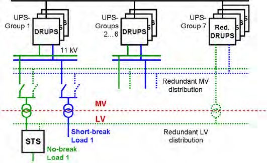
Contents

1    Scope                                                                     3
2    Power Demand and Distribution in today’s Mission Critical Applications   3
3    Limits of LV Distribution in High Power Applications and the Solution     4
4    Integration of UPS-Systems in the MV-Distribution                         5
5    Redundancy Concepts                                                       6
6    Space and Losses are Key Factors for large Systems                        7
7    A MV-UPS serving Air Field Lighting                                      9
8    Power Supply of a 35 MW Semiconductor Fab                                10
9    Redundant MV-UPS at a High Rise Data Centre                              11
10   Conclusion                                                               12
11   References                                                               12

2
1 Scope

The tendency towards Mega Data Centres in the internet and IT business requires an
increasing demand of high reliability power at single locations. More and more large critical
industrial processes rely on a power quality level which can not be provided by the public grid.
The distribution of the electrical power within those installations is realized in medium voltage
(MV) technology because a low voltage (LV) distribution with its high current levels is
physically and economically limited. Likewise a centralized high power uninterruptible power
supply (UPS) system represents a reasonable technological solution, particularly if designed
as a medium voltage UPS or integrated Diesel-rotary-UPS (DRUPS).
Medium voltage UPS technology reduces distribution losses downstream of the UPS and
reduces space due to the lower number of transformers required. Short circuit currents are
limited to a manageable value while the reliability of the power distribution is kept on a high
level when using a high quality UPS system.
The MV distribution allows paralleling of several high power UPS or DRUPS systems on one
common output bus in an N+x configuration and thus avoiding the use of an extensive number
of low voltage switching devices to create redundancy.
The modular design of a line interactive UPS simply allows a replacement of the grid-to-load
interface from low voltage to medium voltage components, keeping the basic parts of the UPS
and the storage the same as for LV applications. In this way the good and familiar experience
with the functionality and maintainability of a reliable LV UPS is maintained.
The paper describes the design of a MV UPS unit and its integration into a redundant MV UPS
system. Space and electrical loss aspects are presented as well as configurations realized in
the field for a Data Centre, an Airport and a Semiconductor Fab.

2 Power Demand and Distribution in today’s Mission Critical
    Applications

Fast growing E-commerce over the last decade forced a rapid rise both in space and electrical
power required to operate data centres. The power density in kilowatt per square metre then
gets higher and cooling power becomes a critical issue. Operators and customers of those
data centres expect a safe and reliable power supply covered by an uninterruptible power
supply (UPS) system. Often, dictated by the risk of thermal runaway, the entire electrical

3
power needed is covered by UPS. Whereas a typical data centre in the early nineties required
some one to three megawatts, today ten to twenty megawatts per installation is not rare.
Also industrial enterprises like semiconductor fabrication, chemical and food industry require
more often a safe power supply because major production losses caused by mains
interruptions can not be tolerated. Single locations have grown larger with a demand on a safe
power supply up to 40 MVA. In addition the production area is often wide spread and
distribution of a high amount of electrical power throughout the location is necessary.
Long distances in the power distribution also have to be overcome in applications like airport,
runway lighting.

3 Limits of LV Distribution in High Power Applications and the
    Solution

At low voltage system levels of 400 volts or 480 volts a maximum capacity of approximately
5 MVA at the common bus is reached very soon. The limitation to 5 MVA is given by the
current capability of bus bars and breakers of about 6000 amps on one side and the short
circuit capability of the switchboards of typically 100 kA on the other side. Higher ratings of
both will let the costs and the dimensions of the switchgear increase dramatically while the
component availability in the market is very limited.
Additionally, high currents require high copper cross sections and cause rather high resistive
losses, both resulting in increasing costs for power transmission.
A way to reduce the currents and to enable a further increase of the power is the move to a
medium voltage (MV) system level. At a typical MV level of 13.2 kV, which is quite common in
the US, the maximum system power rises up to 27 MVA using a standard MV breaker size of
1200 amps and up to 57 MVA with a breaker size of 2500 amps. Medium voltage levels go up
as high as 34.5 kV, allowing a system power rating of up to 70 MVA.
Power distribution using UPSs follow the same electrical rules: Paralleling of UPS modules at
a low voltage level on a common bus is subject to exactly the same limitations. Figure 1
illustrates a possible situation:
    -   The left side shows a group of paralleled UPS modules.
        The addition of a 4th module results in an overload situation (shown in red) of the
        secondary winding of the supply transformer and the downstream bus work.

    -   In the middle the UPS group has been moved to the MV side of the transformer,
        eliminating the overload situation at the bus work attached to the UPS modules. But

4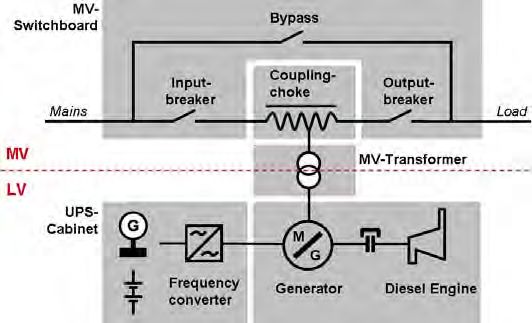
staying with one MV-transformer only this will still overload its secondary winding and
        the LV bus work.

    -   On the right side also parts of the distribution have been moved to the MV side and
        there are three separate transformers used to supply the load. Splitting the LV
        distribution into three separated paths eliminates the overload situation for the
        transformer and the LV bus work.

Figure 1    Paralleling of UPS modules in a high power distribution

4 Integration of UPS-Systems in the MV-Distribution

An obvious way for integrating one ore more standard low voltage UPS modules into a MV
distribution is adding a transformer both at the input and at the output side. These additional
step-up and step-down transformers increase the total number of components, require
additional space and reduce the efficiency of the entire power supply system.

By using an integrated MV-UPS both transformers can be omitted. As shown in Figure 2
further components can be saved if a high power UPS replaces four or five standard dual
conversion LV UPS modules. This configuration offers space savings around the power supply
system and operates at higher efficiency.

Figure 2    MV-UPS technology reduces the total number of components

5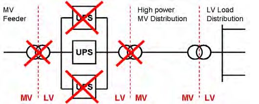
From the different UPS configurations on the market, the line interactive UPS offers the best
choice for integration into a MV system. Figure 3 provides an overview:
- The MV breakers and the coupling choke as the link between mains and load replace
the corresponding LV parts and will fit into the MV switchboard.
- The MV-transformer is an additional part and represents the interface to the remaining
standard LV UPS components.
These standard LV UPS components consist of a synchronous motor-generator which
provides continuous and stabilized power for the load, a frequency converter which connects
the energy storage and an optional Diesel engine attached via a mechanical clutch. The
energy storage may be a chemical battery or a space saving flywheel (POWERBRIDGE) for
bridging short mains interruptions, until the Diesel engine has taken over the load.
A major advantage of such a configuration is the fact that all low voltage components including
the entire control electronic and the operation software are taken from standard and long term
proven LV units.
Figure 3 Design of an integrated MV Diesel Rotary UPS (DRUPS) Type UBTD, showing
the electrical (single line diagram) and the physical (grey boxes)
arrangement of the systems components.
5 Redundancy Concepts
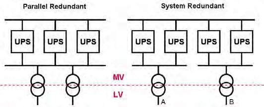
A high quality power supply for mission critical applications presumes a redundancy concept.
For LV designs there are some well known and proven concepts like the N+1 parallel
redundant concept or the N+N system redundant configuration with two redundant A and B
feeders where dual corded loads can be connected to. Without major effort, these concepts
can directly be adapted to a MV layout. They represent simple and clearly arranged
6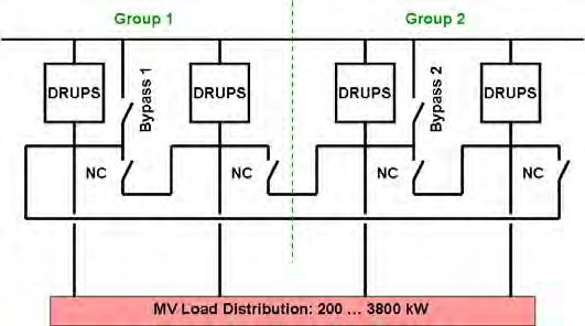
installations, keeping the systems manageable for operators and maintenance personnel.
Figure 4 shows single line diagrams of such systems. Again, the power distribution from the
UPS location to the load transformers is done in medium voltage.

Figure 4     MV-UPS modules in redundant system configurations

A new modern concept to achieve redundancy while limiting the short circuit power is the
Isolated Parallel System (IP-System). The loads are individually fed by separate UPS modules
loaded to a certain degree below full load. A module failure will cause the assigned load to be
fed from a common IP-bus, which is contributed by each of the UPS modules via an IP-Choke.
Figure 5 shows the basic layout of a Medium Voltage IP-System, which allows the realization
of a highly reliable power supply system that offers some benefits compared to the above two
systems [1].

Figure 5     MV-UPS modules integrated in an IP-System

6 Space and Losses are Key Factors for large Systems

One of the major cost issues in a data centre or a production facility is floor space. Reducing
the space for infrastructure equipment like power supplies results in additional space for IT or
manufacturing equipment. Often the available area for the UPS system is given and limited,
particularly in existing buildings, but the required power is increasing. High power UPS
modules with kinetic energy storage in LV or MV technology are well suited to overcome this
challenge.

7
In Table 1 a space comparison between various LV and MV redundant concepts is shown.
These comparisons are based on a load requirement of 10 MVA in total and a feeding voltage
level of 13.2 kV. Typical values for the foot print for static and rotary UPS modules, 5 minute
batteries and switchgear cabinets are taken from manufacturer brochures. MV transformer
and choke are of cast resin dry type with foot prints taken from real projects. The entire
system consists of 7 groups of 1670 kVA each, realized with 3 static UPS units in parallel or
1 rotary unit per group. Each static unit is equipped with a 5 minute battery, the rotary unit with
flywheel storage. Redundancy is achieved by the 7th group, so the configuration is 6+1.
Table 1 Comparison of space required of a 10 MVA, 13.2 kV, N+1 redundant UPS
system in different design concepts
A comparison of the 1st and the 2nd line in Table 1 shows, that the total space required by the
system increases by approximately 33 % if the static LV UPS units are arranged between a
step-up and a step-down transformer. A drastic reduction in space is achieved by using a
rotary UPS both in LV and MV, as shown in lines 3 and 4.
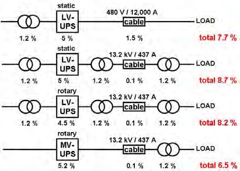
Besides the foot print the electrical losses are an important point to look at, too. Particularly at
long distribution distances in large industry facilities or wide spread airport areas distribution
losses become an issue. A comparison with the above configurations including a cable of 100
meters (328 ft) between UPS and load is shown in Figure 6. The typical losses for UPSs and
transformers are taken from brochures. The losses for the cable have been calculated by
using an adequate type of cable suitable for the current. The LV cable in this example
generates 1.5 % losses (line 1) whereas the MV cable has 0.1 % losses only. The step-up
step-down solution requires another 2.4 % losses for the transformers (line 2), so this is not
the ideal way. The high power one module rotary UPS generates 0.5 % less losses (line 3) but
by removing the step-up step-down transformers the losses decrease substantially (line 4).
Accumulated to losses per year the difference between the last two examples is more than
1 million kilowatt-hours or approx. 100,000 US$.
8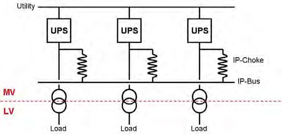
For longer distribution lengths the influence of the cable will rise, which again would give a
better result for the MV distribution.

Figure 6        Comparison of losses of a 10 MVA, 13.2 kV UPS distribution in different
                design concepts

Regarding investment costs the MV UPS and the MV switchgear need to be balanced against
transmission cabling and distribution. MV UPS modules and MV switchgear are obviously
more cost intensive than LV components. These higher costs can partially be compensated by
utilising less copper for the distribution, especially in case of long and complex distribution
networks.
If a MV solution is required for technical reasons, the usage of real MV UPS modules is more
cost effective and more efficient than any integration of standard LV UPS modules in a MV
distribution.

7 A MV-UPS serving Air Field Lighting

Classic applications for high reliability power supplies are safety relevant installations at
airports like airfield lighting, radar systems and control towers. These critical loads are spread
over a wide area across the airfield and the electrical distribution is often realized in medium
voltage.

An example is shown in Figure 7, where a total load of 3.8 MW is served by a MV supply
system at a voltage level of 20 kV consisting of four 1670 kVA Diesel UPS modules in a
parallel redundant configuration. The total length of the MV network is 56 kilometres
(35 miles). The UPS is inserted in series in the existing network. The four DRUPS are
arranged in two groups of two paralleled units each. Depending on the load requirements the
switchgear allows operation as n+1 or as system-system redundant.

9
Figure 7 DRUPS configuration for an airport runway lighting supply
8 Power Supply of a 35 MW Semiconductor Fab
The second example shows the power supply system of a semiconductor fab [2] which
includes a cogeneration plant of nine generator sets with natural gas engines, 3.9 MW each.
Both electricity and heat power is transported over several hundred meters from the energy
plant to the production facility. The voltage level is entirely 20 kV. The role of the UPS system
is interfacing the high quality supply bus with the raw utility bus in order to provide back up
from utility while blocking all grid born disturbances. As a second task the UPS with its
flywheel storage provides stabilisation power for a constant voltage and frequency level during
transient conditions. The unique mode of operation of the flywheel storage allows delivery and
absorption of full power unlike other UPS systems. The ability of bi-directional power flow
enables an excellent frequency control especially under transient conditions, keeping the
whole systems frequency within tight limits. A single line diagram of the principal layout is
shown in Figure 8.
Figure 8 Combining cogeneration and grid backup to a high quality power supply for
a semiconductor fabrication
109 Redundant MV-UPS at a High Rise Data Centre
The third example, to be seen in Figure 9, explains the power supply of a large data centre.
The entire load is almost 40 MVA, split into 28.8 MVA no break and 10.8 MVA short break
load. The supply system is configured as isolated redundant at a voltage level of 11 kV. The
UPS units are arranged in six primary groups of three modules each plus one redundant
group of four modules to provide back up power in case of a failure of one of the six primary
groups. So the total number of UPS units is 22, each of them laid out as a MV Diesel UPS,
providing 1600 kVA of no break and 600 kVA of short break power.
The further down stream distribution is performed in medium voltage to the individual floors of
the data centre and ends in supply transformers complemented by static transfer switches
close to the IT equipment. The isolated redundant back up line is realized with two alternative
power supply paths to the loads: First on the MV level with automatic transfer switches (ATS)
upfront the supply transformers and second on the LV level directly feeding the static transfer
switches (STS) connected to the loads.
Figure 9 Single line of a redundant 40 MVA high quality power supply system for an
internet data centre
10 Conclusion
Increasing power density and increasing total power demand at single sites combined with
rising requirement for high reliability power in IT business and production facilities are today’s
trends. The power supply system has to respond with suitable UPS and distribution designs.
As on the one hand, high power low voltage systems lead to current limitation in the
distribution and as on the other hand often long distances need to be bridged, the step to
medium voltage level is a suitable technical solution. MV systems reduce cable size and
11losses which increases the efficiency of the distribution network. Additionally, the utilization of
integrated high power MV UPS modules reduces the number of components to a minimum.
Basic parts of those modules are taken from standard and proven low voltage equipment,
including control hard- and software. The MV UPS enable a clearly laid out high power system
configuration, keeping its complexity within manageable limits.
11 References
[1] Frank Herbener
Iso-Parallel UPS Configuration
http://www.piller.com/
[2] Stephan Schroeter
Präzisions Power (German language)
E&M Magazine, 15th February 2007
12You can also read