MELLANOX SPECTRUM 1U SWITCH SYSTEMS HARDWARE USER MANUAL - 10/25/40/50/100GBE OPEN ETHERNET SWITCH SYSTEMS MODELS: SN2700, SN2740, SN2410, SN2100 ...
←
→
Page content transcription
If your browser does not render page correctly, please read the page content below
Mellanox Spectrum® 1U Switch
Systems Hardware User Manual
10/25/40/50/100GbE Open Ethernet Switch Systems Models: SN2700, SN2740, SN2410, SN2100, SN2010

Exported on Apr/20/2020 07:09 PM                                                Mellanox Technologies
https://docs.mellanox.com/x/Cw1p

NOTE:
THIS HARDWARE, SOFTWARE OR TEST SUITE PRODUCT (“PRODUCT(S)”) AND ITS RELATED DOCUMENTATION
ARE PROVIDED BY MELLANOX TECHNOLOGIES “AS-IS” WITH ALL FAULTS OF ANY KIND AND SOLELY FOR THE
PURPOSE OF AIDING THE CUSTOMER IN TESTING APPLICATIONS THAT USE THE PRODUCTS IN DESIGNATED
SOLUTIONS. THE CUSTOMER'S MANUFACTURING TEST ENVIRONMENT HAS NOT MET THE STANDARDS SET BY
MELLANOX TECHNOLOGIES TO FULLY QUALIFY THE PRODUCT(S) AND/OR THE SYSTEM USING IT. THEREFORE,
MELLANOX TECHNOLOGIES CANNOT AND DOES NOT GUARANTEE OR WARRANT THAT THE PRODUCTS WILL
OPERATE WITH THE HIGHEST QUALITY. ANY EXPRESS OR IMPLIED WARRANTIES, INCLUDING, BUT NOT LIMITED
TO, THE IMPLIED WARRANTIES OF MERCHANTABILITY, FITNESS FOR A PARTICULAR PURPOSE AND
NONINFRINGEMENT ARE DISCLAIMED. IN NO EVENT SHALL MELLANOX BE LIABLE TO CUSTOMER OR ANY
THIRD PARTIES FOR ANY DIRECT, INDIRECT, SPECIAL, EXEMPLARY, OR CONSEQUENTIAL DAMAGES OF ANY
KIND (INCLUDING, BUT NOT LIMITED TO, PAYMENT FOR PROCUREMENT OF SUBSTITUTE GOODS OR SERVICES;
LOSS OF USE, DATA, OR PROFITS; OR BUSINESS INTERRUPTION) HOWEVER CAUSED AND ON ANY THEORY OF
LIABILITY, WHETHER IN CONTRACT, STRICT LIABILITY, OR TORT (INCLUDING NEGLIGENCE OR OTHERWISE)
ARISING IN ANY WAY FROM THE USE OF THE PRODUCT(S) AND RELATED DOCUMENTATION EVEN IF ADVISED OF
THE POSSIBILITY OF SUCH DAMAGE.

                             Mellanox Technologies
                             350 Oakmead Parkway Suite 100
                             Sunnyvale, CA 94085, U.S.A.
                             www.mellanox.com
                             Tel: (408) 970-3400
                             Fax: (408) 970-3403

© Copyright 2020. Mellanox Technologies Ltd. All Rights Reserved.
Mellanox® and the Mellanox logo are registered trademarks of Mellanox Technologies, Ltd.
Additional trademarks used in this document are listed under http://www.mellanox.com/page/trademarks.
All other trademarks are property of their respective owners.

2                                                                                                       Mellanox Technologies
Table of Contents
1          Ordering Information ............................................................................................................................................... 7
1.1             SN2700 Ordering Part Numbers ........................................................................................................................7
1.2             SN2410 Ordering Part Numbers ........................................................................................................................7
1.3             SN2100 Ordering Part Numbers ........................................................................................................................8
1.4             SN2010 Ordering Part Numbers ........................................................................................................................9
2          Introduction............................................................................................................................................................ 10
2.1             Speed and Switching Capabilities .................................................................................................................... 11
2.2             Management Interfaces, PSUs and Fans ........................................................................................................12
2.3             Features ...........................................................................................................................................................12
2.4             Certifications.....................................................................................................................................................12
3          Installation ............................................................................................................................................................. 13
3.1             System Installation and Initialization ................................................................................................................13
3.2             Safety Warnings ...............................................................................................................................................13
3.3             Air Flow ............................................................................................................................................................16
3.4             Package Contents ............................................................................................................................................17
3.5             19” System Mounting Options ..........................................................................................................................17
3.6             SN2700 Static Rail Kit ......................................................................................................................................17
3.6.1                Removing the System from the Rack......................................................................................................... 21
3.7             SN2700 Telescopic Rail Kit ..............................................................................................................................21
3.7.1                Removing the System from the Rack......................................................................................................... 24
3.8             SN2740/SN2410 Static Rail Kit ........................................................................................................................25
3.9             SN2100/SN2010 Side by Side Mounting Rail Kit .............................................................................................27
3.10            SN2100/SN2010 Static Single Switch Rail Kit .................................................................................................31
3.11            Cable Installation..............................................................................................................................................33
3.11.1               Splitter (Breakout) Cables and Adapters .................................................................................................... 35
3.11.1.1                  Using Splitter (Breakout) Cables with Mellanox Onyx (MLNX-OS) ....................................................... 35
3.11.1.2                  Using Splitter (Breakout) Cables with Cumulus Linux........................................................................... 35
3.11.1.3                  SN2700 and SN2740 Splitting Options ................................................................................................. 35
3.11.1.4                  SN2410 Splitting Options ...................................................................................................................... 36
3.11.1.5                  SN2100 Splitting Options ...................................................................................................................... 36
3.11.1.6                  SN2010 Splitting Options ..................................................................................................................... 36
3.12            Initial Power On ................................................................................................................................................37
3.13            System Bring-Up ..............................................................................................................................................38
3.13.1               Configuring Network Attributes Using Mellanox Onyx (MLNX-OS) ............................................................ 38
3.13.1.1                  Manual Host Configuration.................................................................................................................... 38
3.13.1.2                  Disable Dynamic Host Configuration Protocol (DHCP)......................................................................... 41

3                                                                                                                                                   Mellanox Technologies
3.13.1.3                  Remote Connection with Mellanox Onyx (MLNX-OS) .......................................................................... 42
3.13.2               Configuring Network Attributes Using Cumulus Linux................................................................................ 42
3.13.2.1                  Remote Connection with Cumulus Linux .............................................................................................. 42
3.14            FRU Replacements ..........................................................................................................................................42
3.14.1               Power Supply ............................................................................................................................................. 42
3.14.2               Fans ........................................................................................................................................................... 43
4          Interfaces............................................................................................................................................................... 45
4.1             Data Interfaces .................................................................................................................................................45
4.1.1                Supported Passive Cables in SN2010bM .................................................................................................. 46
4.2             Speed ...............................................................................................................................................................46
4.3             RS232 (Console)..............................................................................................................................................46
4.4             Management ....................................................................................................................................................46
4.5             USB ..................................................................................................................................................................47
4.6             Reset Button.....................................................................................................................................................47
4.7             Status and Port LEDs.......................................................................................................................................47
4.8             LED Notifications..............................................................................................................................................47
4.8.1                System Status LED .................................................................................................................................... 48
4.8.2                Fan Status LED .......................................................................................................................................... 50
4.8.3                Power Supply Status LEDs ........................................................................................................................ 51
4.8.4                Unit Identification LED................................................................................................................................ 53
4.8.5                Bad Port LED ............................................................................................................................................. 53
4.8.6                Port LEDs ................................................................................................................................................... 54
4.9             Inventory Information........................................................................................................................................55
5          Software Management .......................................................................................................................................... 57
5.1             Upgrading Software..........................................................................................................................................57
5.1.1                Mellanox Onyx (MLNX-OS) Software Upgrade.......................................................................................... 57
5.1.2                Switch Firmware Update ............................................................................................................................ 57
5.1.3                Cumulus Linux Software Upgrade.............................................................................................................. 57
6          Troubleshooting..................................................................................................................................................... 58
7          Specifications ........................................................................................................................................................ 60
7.1             SN2700 Series .................................................................................................................................................60
7.2             SN2740 Series .................................................................................................................................................61
7.3             SN2410 Series .................................................................................................................................................62
7.4             SN2100 Series .................................................................................................................................................64
7.5             SN2010 Series .................................................................................................................................................65
8          Appendixes............................................................................................................................................................ 67
8.1             Accessory and Replacement Parts ..................................................................................................................67
8.2             Thermal Threshold Definitions .........................................................................................................................68

4                                                                                                                                                   Mellanox Technologies

8.3         Interface Specifications ....................................................................................................................................68
8.3.1            QSFP28 Pin Description ............................................................................................................................ 68
8.3.2            SFP28 Pin Description ............................................................................................................................... 71
8.3.3            RJ45 to DB9 Harness Pinout ..................................................................................................................... 72
8.3.4            RJ45 to RJ45 Harness .............................................................................................................................. 73
8.4         Disassembly and Disposal ...............................................................................................................................73
8.4.1            Disassembly Procedure ............................................................................................................................. 73
8.4.2            Disposal...................................................................................................................................................... 74
9       Document Revision History ................................................................................................................................... 75

5                                                                                                                                              Mellanox Technologies

Relevant for Models: SN2700, SN2740, SN2410, SN2100 and SN2010

About this Manual
This manual describes the installation and basic use of Mellanox Ethernet switches based on the Mellanox Spectrum IC device.
Ordering Information
See Ordering Information.
Intended Audience
This manual is intended for IT managers and system administrators.
Related Documentation

                              Document                                                   Description

    Mellanox Onyx (MLNX-OS) User Manual                      This document contains information regarding the configuration and
                                                             management of the Mellanox Onyx (MLNX-OS) software. See http://
                                                             www.mellanox.com/page/mlnx_onyx.

    Cumulus Linux User Guide                                 This document contains information regarding the configuration and
                                                             management of the Cumulus® Linux® software. See https://
                                                             docs.cumulusnetworks.com/display/DOCS.

    Open Network Install Environment (ONIE) Quick Start      See https://github.com/opencomputeproject/onie/wiki/Quick-Start-
    Guide                                                    Guide/.

    Hands-on workshops                                       Cumulus on-site/remote training: https://academy.mellanox.com/en/
                                                             cumulus-linux/
                                                             Mellanox Onyx on-site/remote training: https://
                                                             academy.mellanox.com/en/network-pro-private/

    On-site/remote services                                  http://www.mellanox.com/globalservices/index.php/project-delivery-
                                                             services-on-site-ethernet-kick-start-package/
                                                             For any tailor-made service, contact services-sales@mellanox.com.

Revision History
A list of the changes made to this document are provided in Document Revision History.

6                                                                                                        Mellanox Technologies
1 Ordering Information
The following table lists ordering information for the available systems.
Please pay attention to the airflow direction when ordering your system. For more details, see Air Flow.

1.1 SN2700 Ordering Part Numbers
      OPN                                                        Marketing Description

    MSN2700-      Mellanox Spectrum based 40GbE, 1U Open Ethernet Switch with Mellanox Onyx (MLNX-OS), 32 QSFP28
    BS2F          ports, 2 Power Supplies (AC), x86 CPU, Standard depth, P2C airflow, Rail Kit, RoHS6

    MSN2700-      Mellanox Spectrum 40GbE 1U switch w/Cumulus Linux, 32 QSFP28 ports, 2 AC PSUs, x86 2-core, standard
    BS2FC         depth, P2C airflow, Rail Kit, RoHS6, (Cumulus License Key is required)

    MSN2700-      Mellanox Spectrum based 40GbE 1U Open Switch with ONIE, 32 QSFP28 ports, 2 Power Supplies (AC),
    BS2FO         Standard depth, x86 CPU, P2C airflow, Rail Kit, RoHS6

    MSN2700-      Mellanox Spectrum based 40GbE, 1U Open Ethernet Switch with Mellanox Onyx (MLNX-OS), 32 QSFP28
    BS2R          ports, 2 Power Supplies (AC), x86 CPU, Standard depth, C2P airflow, Rail Kit, RoHS6

    MSN2700-      Mellanox Spectrum 40GbE 1U switch w/Cumulus Linux, 32 QSFP28 ports, 2 AC PSUs, x86 2-core, standard
    BS2RC         depth, C2P airflow, Rail Kit, RoHS6, (Cumulus License Key is required)

    MSN2700-      Mellanox Spectrum based 100GbE, 1U Open Ethernet Switch with Mellanox Onyx (MLNX-OS), 32 QSFP28
    CS2F          ports, 2 Power Supplies (AC), x86 CPU, Standard depth, P2C airflow, Rail Kit, RoHS6

    MSN2700-      Mellanox Spectrum 100GbE 1U switch w/Cumulus Linux, 32 QSFP28 ports, 2 AC PSUs, x86 2-core, standard
    CS2FC         depth, P2C airflow, Rail Kit, RoHS6, (Cumulus License Key is required)

    MSN2700-      Mellanox Spectrum based 100GbE 1U Open Switch with ONIE, 32 QSFP28 ports, 2 Power Supplies (AC),
    CS2FO         Standard depth, x86 CPU, P2C airflow, Rail Kit, RoHS6

    MSN2700-      Mellanox Spectrum based 100GbE, 1U Open Ethernet Switch with Mellanox Onyx (MLNX-OS), 32 QSFP28
    CS2R          ports, 2 Power Supplies (AC), x86 CPU, Standard depth, C2P airflow, Rail Kit, RoHS6

    MSN2700-      Mellanox Spectrum 100GbE 1U switch w/Cumulus Linux, 32 QSFP28 ports, 2 AC PSUs, x86 2-core, standard
    CS2RC         depth, C2P airflow, Rail Kit, RoHS6, (Cumulus License Key is required)

    MSN2700-      Mellanox Spectrum based 100GbE 1U Open Ethernet switch with ONIE, 32 QSFP28 ports, 2 power supplies
    CS2RO         (AC), x86 CPU, standard depth, C2P airflow, Rail Kit

    MSN2700-      Mellanox Spectrum based 100GbE, 1U Open Ethernet Switch with ONIE, 32 QSFP28 ports, 2 power-supplies
    CBBFO         (DC), x86 CPU, short depth, P2C airflow, Rail Kit

1.2 SN2410 Ordering Part Numbers
      OPN                                                       Marketing Description

    MSN2410-     Mellanox Spectrum 10GbE/100GbE switch w/Cumulus Linux, 48 SFP28 ports + 8 QSFP28 ports, 2 AC PSUs, x86
    BB2FC        2-core, short depth, P2C air flow, Rail Kit, (Cumulus License Key is required)

7                                                                                                          Mellanox Technologies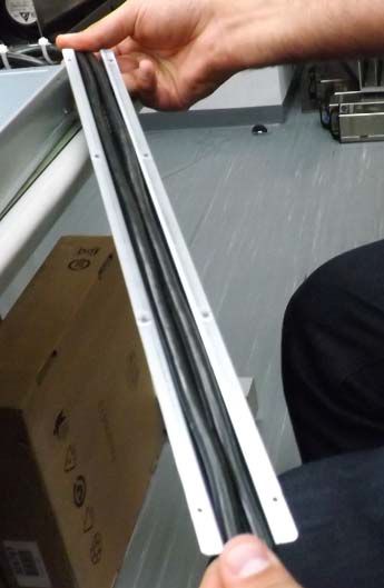
OPN                                                Marketing Description

    MSN2410-   Mellanox Spectrum based 10GbE/100GbE 1U Open Ethernet switch with ONIE, 48 SFP28 ports, 8 QSFP28 ports,
    BB2FO      2 power supplies (AC), x86 dual core, Short depth, P2C airflow, Rail Kit, RoHS6

    MSN2410-   Mellanox Spectrum based 10GbE/100GbE 1U Open Ethernet switch with Mellanox Onyx (MLNX-OS), 48 SFP28
    BB2R       ports, 8 QSFP28 ports, 2 power supplies (AC), x86 dual core, Short depth, C2P airflow, Rail Kit, RoHS6

    MSN2410-   Mellanox Spectrum based 10GbE/100GbE 1U Open Ethernet switch with ONIE, 48 SFP28 ports and 8 QSFP28
    BB2RO      ports, 2 power supplies (AC), x86 CPU, short depth, C2P airflow, Rail Kit

    MSN2410-   Mellanox Spectrum based 10GbE/100GbE 1U Open Ethernet switch with Cumulus Linux, 48 SFP28 ports and 8
    BB2RC      QSFP28 ports, 2 power supplies (AC), x86 CPU, short depth, C2P airflow, Rail Kit

    MSN2410-   Mellanox Spectrum based 10GbE/100GbE 1U Open Ethernet switch with Cumulus Linux, 48 SFP28 ports and 8
    BBBFC      QSFP28 ports, 2 power supplies (DC), x86 CPU, short depth, P2C airflow, Rail Kit

    MSN2410-   Mellanox Spectrum based 25GbE/100GbE 1U Open Ethernet switch with Mellanox Onyx (MLNX-OS), 48 SFP28
    CB2F       ports, 8 QSFP28 ports, 2 power supplies (AC), x86 dual core, Short depth, P2C airflow, Rail Kit, RoHS6

    MSN2410-   Mellanox Spectrum 25GbE/100GbE switch w/Cumulus Linux, 48 SFP28 ports + 8 QSFP28 ports, 2 AC PSUs, x86
    CB2FC      2 core, short depth, P2C air flow, Rail Kit, (Cumulus License Key is required)

    MSN2410-   Mellanox Spectrum based 25GbE/100GbE 1U Open Ethernet switch with ONIE, 48 SFP28 ports, 8 QSFP28 ports,
    CB2FO      2 power supplies (AC), x86 dual core, Short depth, P2C airflow, Rail Kit, RoHS6

    MSN2410-   Mellanox Spectrum based 25GbE/100GbE 1U Open Ethernet switch with Mellanox Onyx (MLNX-OS), 48 SFP28
    CB2R       ports, 8 QSFP28 ports, 2 power supplies (AC), x86 dual core, Short depth, C2P airflow, Rail Kit, RoHS6

    MSN2410-   Mellanox Spectrum 25GbE/100GbE switch w/Cumulus Linux, 48 SFP28 ports + 8 QSFP28 ports, 2 AC PSUs, x86
    CB2RC      2 core, short depth, C2P air flow, Rail Kit, (Cumulus License Key is required)

    MSN2410-   Mellanox Spectrum based 25GbE/100GbE 1U Open Ethernet switch with ONIE, 48 SFP28 ports, 8 QSFP28 ports,
    CB2RO      2 power supplies (AC), x86 dual core, Short depth, C2P airflow, Rail Kit, RoHS6

    MSN2410-   Mellanox Spectrum based 25GbE/100GbE 1U Open Ethernet switch with Cumulus Linux, 48 SFP28 ports and 8
    CBBRC      QSFP28 ports, 2 power supplies (DC), x86 CPU, short depth, C2P airflow, Rail Kit

1.3 SN2100 Ordering Part Numbers
      OPN                                                Marketing Description

    MSN2100-   Mellanox Spectrum 40GbE 1U switch w/Cumulus Linux, 16 QSFP28 ports, 2 AC PSUs, x86 2 core, short depth,
    BB2FC      P2C airflow, Rails to be purchased separately, (Cumulus License Key is required)

    MSN2100-   Mellanox Spectrum based 40GbE 1U Open Switch with ONIE, 16 QSFP28 ports, 2 AC PSUs, x86 2-core, short
    BB2FO      depth, P2C airflow, Rail Kit must be purchased separately, RoHS6

    MSN2100-   Mellanox Spectrum based 40GbE, 1U Open Ethernet Switch with Mellanox Onyx (MLNX-OS), 16 QSFP28 ports,
    BB2R       2 AC PSUs, x86 2-core, short depth, C2P airflow, Rail Kit must be purchased separately, RoHS6

    MSN2100-   Mellanox Spectrum 40GbE 1U switch w/Cumulus Linux, 16 QSFP28 ports, 2 AC PSUs, x86 2-core, short depth,
    BB2RC      C2P airflow, Rails to be purchased separately, (Cumulus License Key is required)

8                                                                                                 Mellanox Technologies
OPN                                                   Marketing Description

    MSN2100-   Mellanox Spectrum based 40GbE 1U Open Ethernet switch with ONIE, 16 QSFP28 ports, 2 power supplies (AC),
    BB2RO      x86 CPU, short depth, C2P airflow. Rail Kit must be purchased separately

    MSN2100-   Mellanox Spectrum based 100GbE, 1U Open Ethernet Switch with Mellanox Onyx (MLNX-OS), 16 QSFP28
    CB2F       ports, 2 AC PSUs, x86 2-core, short depth, P2C airflow, Rail Kit must be purchased separately, RoHS6

    MSN2100-   Mellanox Spectrum 100GbE 1U switch w/Cumulus Linux, 16 QSFP28 ports, 2 AC PSUs, x86 2-core, short depth,
    CB2FC      P2C airflow, Rails to be purchased separately, (Cumulus License Key is required)

    MSN2100-   Mellanox Spectrum based 100GbE 1U Open Switch with ONIE, 16 QSFP28 ports, 2 AC PSUs, x86 2-core, short
    CB2FO      depth, P2C airflow, Rail Kit must be purchased separately, RoHS6

    MSN2100-   Mellanox Spectrum based 100GbE, 1U Open Ethernet Switch with Mellanox Onyx (MLNX-OS), 16 QSFP28
    CB2R       ports, 2 AC PSUs, x86 2-core, short depth, C2P airflow, Rail Kit must be purchased separately, RoHS6

    MSN2100-   Mellanox Spectrum 100GbE 1U switch w/Cumulus Linux, 16 QSFP28 ports, 2 AC PSUs, x86 2-core, short depth,
    CB2RC      C2P airflow, Rails to be purchased separately, (Cumulus License Key is required)

    MSN2100-   Mellanox Spectrum based 100GbE 1U Open Ethernet switch with ONIE, 16 QSFP28 ports, 2 power supplies
    CB2RO      (AC), x86 CPU, short depth, C2P airflow. Rail Kit must be purchased separately

1.4 SN2010 Ordering Part Numbers
      OPN                                                    Marketing Description

    MSN2010-   Mellanox Spectrum-based 25GbE/100GbE, 1U Open Ethernet Switch with Mellanox Onyx, 18 SFP28 and 4
    CB2F       QSFP28 ports, 2 Power Supplies (AC), short depth, x86 quad core, P2C airflow, Rail Kit must be purchased
               separately

    MSN2010-   Mellanox Spectrum-based 25GbE/100GbE 1U switch w/Cumulus Linux, 18 SFP28 and 4 QSFP28 ports, 2 AC
    CB2FC      PSUs, x86 4-core, short depth, P2C airflow, Rails to be purchased separately, (Cumulus License is provided at no
               cost with purchase of SUP-SN2010-CL-XX)

    MSN2010-   Mellanox Spectrum-based 25GbE/100GbE, 1U Open Ethernet Switch with ONIE, 18 SFP28 ports and 4 QSFP28
    CB2FO      ports, 2 Power Supplies (AC), x86 quad core, short depth, P2C airflow, Rail Kit must be purchased separately

    MSN2010-   Mellanox Spectrum-based 25GbE/100GbE, 1U Open Ethernet Switch with Mellanox Onyx, 18 SFP28 ports and 4
    CB2R       QSFP28 ports, 2 Power Supplies (AC), short depth, x86 quad core, C2P airflow, Rail Kit must be purchased
               separately

    MSN2010-   Spectrum-based 25GbE/100GbE 1U switch w/Cumulus Linux, 18 SFP28 and 4 QSFP28 ports, 2 AC PSUs, x86
    CB2RC      4-core, short depth, C2P airflow, Rails to be purchased separately, (Cumulus License is provided at no cost with
               purchase of SUP-SN2010-CL-XX)

    MSN2010-   Mellanox Spectrum based 25GbE/100GbE 1U Open Ethernet switch with ONIE, 18 SFP28 ports and 4 QSFP28
    CB2RO      ports, 2 power supplies (AC), x86 CPU, short depth, C2P airflow. Rail Kit must be purchased separately

9                                                                                                        Mellanox Technologies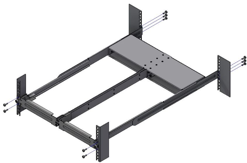
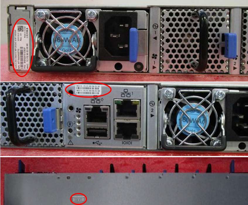
2 Introduction
Mellanox Spectrum® based 1U switch systems are an ideal spine and Top of Rack (ToR) solution, allowing maximum flexibility, with
port speeds spanning from 10Gb/s to 100Gb/s per port, and port density that enables full rack connectivity to any server at any speed.
The uplink ports allow a variety of blocking ratios that suit any application requirement. Powered by the Mellanox Spectrum ASIC,
the systems carry whopping switching and processing capacities in a compact 1U form factor.
Keeping with the Mellanox tradition of setting performance record switch systems, the Mellanox Spectrum-based systems introduce
the world’s lowest latency for 100GbE switching and routing elements, and do so while having the lowest power consumption in the
market. They enable the use of 10, 25, 40, 50 and 100GbE in a large scale without changing power infrastructure facilities.
The Mellanox Spectrum-based 1U switch systems are a part of Mellanox’s complete end-to-end solution, which provides 10GbE
through 100GbE interconnectivity within the data center. Other devices in this solution include ConnectX®-4 based network interface
cards, and LinkX® copper or fiber cabling/transceivers. This end-to-end solution is topped with NEO, a management application that
relieves some of the major obstacles standing in the way when deploying a network. NEO enables a fully certified and interoperable
design, speeds up time to service and RoI. The systems introduce hardware capabilities for multiple tunneling protocols that enable
increased reachability and scalability for today’s data centers. Implementing MPLS, NVGRE and VXLAN tunneling encapsulations in
the network layer of the data center allows more flexibility for terminating a tunnel by the network, in addition to termination on the
server endpoint.
While Mellanox Spectrum provides the thrust and acceleration that powers the switch systems, they get yet another angle of
capabilities, running with a powerful x86-based processor, which allows them to not only be the highest performing switch fabric
elements, but also grants them the ability to incorporate a Linux running server into the same device. This opens up multiple
application aspects of utilizing the high CPU processing power and the best switching fabric, to create a powerful machine with
unique appliance capabilities that can improve numerous network implementation paradigms. The Mellanox Spectrum-based 1U
switch systems support the Open Network Install Environment (ONIE) for zero touch installations of network operating systems.
While all Ethernet systems can be purchased preloaded with Mellanox Onyx (MLNX-OS), the SN2000 switches (in both the 100GbE
and the 40GbE versions) are offered, in addition, with Cumulus Linux support, as an alternative operating system. For a full list of all
available ordering options, see Ordering Information.
SN2700 Front View

SN2740 Front View

SN2410 Front View

SN2100 Front View

10                                                                                                            Mellanox Technologies
SN2010 Front View

SN2700 and SN2410 Rear View

SN2740 Rear View

SN2100 Rear View

SN2010 Rear View

2.1 Speed and Switching Capabilities
The table below describes maximum throughput and interface speed per system model.

     System Model           10/25GbE SFP28 Interfaces*        40/50/56/100GbE QSFP28 Interfaces*      Max Throughput

 SN2700                                 64                                    32                   6.4Tb/s
                             (using QSFP to SFP splitter
                                      cables)

11                                                                                                 Mellanox Technologies
System Model 10/25GbE SFP28 Interfaces* 40/50/56/100GbE QSFP28 Interfaces* Max Throughput
SN2740 64 32 6.4Tb/s
(using QSFP to SFP splitter
cables)
SN2410 Total 64, 48SFP+16 8 4Tb/s
(using QSFP to SFP splitter
cables)
SN2100 64 16 3.2Tb/s
(using QSFP to SFP splitter (or 32 50GbE interfaces when using
cables) QSFP to 2xQSFP splitter cables)
SN2010 34 4 1.7Tb/s
(using QSFP to SFP splitter (or 8 50GbE interfaces when using
cables) QSFP to 2xQSFP splitter cables)
*The system can support different interfaces and speed rates using QSFP+ to SFP+ adapters or hybrid cables. For further information,
see Splitter (Breakout) Cables and Adapters.
2.2 Management Interfaces, PSUs and Fans
The table below lists the various management interfaces, PSUs and fans per system model.
System Model USB MGT Console PSU Fan
SN2700 Rear Rear (2 ports) Rear 2 units 4 units
SN2740 Front Front (1 port) Front 2 units 4 units
SN2410 Rear Rear (2 ports) Rear 2 units 4 units
SN2100 Front (mini USB) Front (1 port) Front 2 units (non- 4 units (non-
replaceable) replaceable)
SN2010 Front Front (1 port) Front 2 units (non- 4 units (non-
replaceable) replaceable)
2.3 Features
For a full feature list, please refer to the system’s product brief. Go to http://www.mellanox.com. In the main menu, click on Products
> Ethernet Switch Systems, and select the desired product page.
2.4 Certifications
The list of certifications (such as EMC, Safety and others) per system for different regions of the world is located on the Mellanox
website at http://www.mellanox.com/page/environmental_compliance.
12 Mellanox Technologies3 Installation
3.1 System Installation and Initialization
Installation and initialization of the system require attention to the normal mechanical, power, and thermal precautions for rack-
mounted equipment.
The rack mounting holes conform to the EIA-310 standard for 19-inch racks. Take precautions to guarantee proper
ventilation in order to maintain good airflow at ambient temperature.
Unless otherwise specified, Mellanox products are designed to work in an environmentally controlled data center with low
levels of gaseous and dust (particulate) contamination.
The operation environment should meet severity level G1 as per ISA 71.04 for gaseous contamination and ISO 14644-1
class 8 for cleanliness level.
The installation procedure for the system involves the following phases:
Step Procedure See
1 Follow the safety warnings Safety Warnings
2 Pay attention to the air flow consideration within the system Air Flow
and rack
3 Make sure that none of the package contents is missing or Package Contents
damaged
4 Mount the system into a rack enclosure 19" System Mounting Options
5 Power on the system Initial Power On
6 Perform system bring-up System Bring-Up
7 [Optional] FRU replacements FRU Replacements
3.2 Safety Warnings
Prior to the installation, please review the safety warnings. Note that not all warnings may apply to all models.
Safety warnings are provided here in the English language. For safety warnings in other languages, refer to the 1U Switch
Installation Safety Instructions document available on mellanox.com.
Safety Warnings (English)
Installation Instructions
Read all installation instructions before connecting the equipment to the power source.
Bodily Injury Due to Weight
13 Mellanox TechnologiesUse enough people to safely lift this product.
Heavy Equipment
This equipment is heavy and should be moved using a mechanical lift to avoid injuries.
Risk of Electric Shock!
• With the fan module removed power pins are accessible within the module cavity.
Do not insert tools or body parts into the fan module cavity.
• For AC powered switch systems: Disconnecting one power supply only disconnects one module. To isolate the unit
completely, all connected power supplies must be disconnected.
Over-temperature
This equipment should not be operated in an area with an ambient temperature exceeding the maximum recommended: 45°C
(113°F). Moreover, to guarantee proper ventilation, allow at least 8cm (3 inches) of clearance around the ventilation openings.
Stacking the Chassis
The chassis should not be stacked on any other equipment. If the chassis falls, it can cause bodily injury and equipment damage.
Redundant Power Supply Connection - Electrical Hazard
This product includes a redundant power or a blank in its place. In case of a blank power supply, do not operate the product with
the blank cover removed or not securely fastened.
Double Pole/Neutral Fusing
This system has double pole/neutral fusing. Remove all power cords before opening the cover of this product or touching any
internal parts.
Multiple Power Inlets
Risk of electric shock and energy hazard. The PSUs are all independent. Disconnect all power supplies to ensure a powered
down state inside of the switch platform.
During Lightning - Electrical Hazard
During periods of lightning activity, do not work on the equipment or connect or disconnect cables.
Copper Cable Connecting/Disconnecting
Copper cables are heavy and not flexible, as such they should be carefully attached to or detached from the connectors. Refer to
the cable manufacturer for special warnings/instructions.
14 Mellanox TechnologiesRack Mounting and Servicing
When this product is mounted or serviced in a rack, special precautions must be taken to ensure that the system remains stable.
In general you should fill the rack with equipment starting from the bottom to the top.
Equipment Installation
This equipment should be installed, replaced, and/or serviced only by trained and qualified personnel.
Equipment Disposal
Disposal of this equipment should be in accordance to all national laws and regulations.
Local and National Electrical Codes
This equipment should be installed in compliance with local and national electrical codes.
Installation Codes
This device must be installed according to the latest version of the country national electrical codes. For North America,
equipment must be installed in accordance to the applicable requirements in the US National Electrical Code and the Canadian
Electrical Code.
Battery Replacement
Warning: Replace only with UL Recognized battery, certified for maximum abnormal charging current not less than 4mA. There
is a risk of explosion should the battery be replaced with a battery of an incorrect type. Dispose of used batteries according to the
instructions.
UL Listed and CSA Certified Power Supply Cord
For North American power connection, select a power supply cord that is UL Listed and CSA Certified, 3 - conductor, [16
AWG], terminated with a molded plug rated at 125 V, [13 A], with a minimum length of 1.5m [six feet] but no longer than 4.5m.
For European connection, select a power supply cord that is internationally harmonized and marked “”, 3 - conductor,
minimum 1.0 mm2 wire, rated at 300 V, with a PVC insulated jacket. The cord must have a molded plug rated at 250 V, 10 A.
Installation codes
This device must be installed according to the latest version of the country national electrical codes. For North America,
equipment must be installed in accordance to the applicable requirements in the US National Electrical Code and the Canadian
Electrical Code.
Interconnection of Units
Cables for connecting to the unit RS232 and Ethernet Interfaces must be UL certified type DP-1 or DP-2. (Note- when residing
in non LPS circuit)
Overcurrent Protection
A readily accessible Listed branch circuit overcurrent protective device rated 20 A must be incorporated in the building wiring.
Do Not Use the Switch as a Shelf or Work Space
Caution: Slide/rail mounted equipment is not to be used as a shelf or a work space. The rails are not intended for sliding
the unit away from the rack. It is for permanent installation at final resting place only, not used for service and maintenance
15 Mellanox TechnologiesWEEE Directive
According to the WEEE Directive 2002/96/EC, all waste electrical and electronic equipment (EEE) should be collected
separately and not disposed of with regular household waste. Dispose of this product and all of its parts in a responsible
and environmentally friendly way.
Country of Norway Power Restrictions
This unit is intended for connection to a TN power system and an IT power system of Norway only.
3.3 Air Flow
The following information does not apply to SN2100/SN2010. In the SN2100/SN2010 systems, the fan units are non-
replaceable.
Mellanox systems are offered with two air flow patterns:
• Power (rear) side inlet to connector side outlet - marked with blue power supplies/fans FRUs’ handles.
Air Flow Direction Marking - Power Side Inlet to Connector Side Outlet
• Connector (front) side inlet to power side outlet - marked with red power supplies/fans FRUs’ handles.
Air Flow Direction Marking - Connector Side Inlet to Power Side Outlet
All servers and systems in the same rack should be planned with the same airflow direction.
All FRU components need to have the same air flow direction. A mismatch in the air flow will affect the heat dissipation.
The table below provides an air flow color legend and respective OPN designation.
Direction Description and OPN Designation
Connector side inlet to power side outlet. Red latches are placed on the power inlet
side.
OPN designation is “-R”.
16 Mellanox TechnologiesDirection Description and OPN Designation
Power side inlet to connector side outlet. Blue latches are placed on the power inlet
side.
OPN designation is “-F”.
3.4 Package Contents
Before installing your new system, unpack it and check against the parts list below that all the parts have been sent. Check the parts
for visible damage that may have occurred during shipping.
The SN2700 and SN2410 package content is as follows:
• 1 – System
• 1 – Rail kit
• 1 – Power cable for each power supply unit – Type C13-C14
• 1 – Cable retainer for each power supply unit
• 1 – DB9 to RJ-45 2m harness
• 1 - RJ-45 to RJ-45 2m harness
The SN2100/SN2010 package content is as follows:
• 1 – System
• 1 – Power cable for each power supply unit – Type C13-C14
• 1 – DB9 to RJ-45 2m harness
A designated rail kit for the SN2100/SN2010 systems can be purchased separately.
If anything is damaged or missing, contact your sales representative at support@mellanox.com.
3.5 19” System Mounting Options
• By default, the SN2700 systems are shipped with the static rail kit described SN2700 Static Rail Kit.
• The SN2410 and SN2740 systems are shipped with the static rail kit described in SN2740/SN2410 Static Rail Kit.
• For the telescopic rail kit installation instructions (can be used with SN2700 only), see SN2700 Telescopic Rail Kit.
• The SN2100/SN2010 system is shipped without a rail kit and a designated rail kit can be purchased separately. For installation
instructions, see SN2100/SN2010 Side by Side Mounting Rail Kit.
• SN2100/SN2010 Static Single Switch Rail Kit
3.6 SN2700 Static Rail Kit
Kit OPN Rack Size and Rack Depth Range
MTEF-KIT-A Short (17”-24”) or Standard (24”-34”)
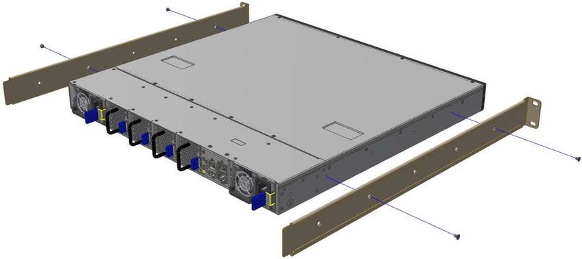
The following parts are included in the static rail kit (see figure below):
• 2x Rack mount rails (A)
17 Mellanox Technologies• 2x Rack mount brackets (B)
• 2x Rack mount blades (C)
• 8x M6 Standard cage nuts¹ ² and 8x M6 Standard pan-head Phillips screws¹ (D)
• 4x Phillips100 DEG F.H TYPE-I ST.ST 6-32 X 1/4 screws with a round patch (E)
¹ Other threads are available by special order: M5, 10-32, 12-24. ² G-type cage-nut is available by special order.
Rack Rail Kit Parts
Prerequisites:
Before mounting the system to the rack, select the way you wish to place the system. Pay attention to the airflow within the rack
cooling, connector and cabling options.
While planning how to place the system, consider the two installation options shown in the figure below, and review the following
points:
• Make sure the system air flow is compatible with your installation selection. It is important to keep the airflow within the rack
in the same direction.
• Note that the part of the system to which you choose to attach the rails (the front panel direction, as demonstrated in Option 1
or the FRUs direction, as demonstrated in Option 2) will determine the system’s adjustable side. The system’s part to which
the brackets are attached will be adjacent to the cabinet.
• The FRU side is extractable. Mounting the rack brackets inverted to the FRU side (Option 2) will allow you to slide the FRUs,
in and out.
Installation Option 1 & Option 2
18 Mellanox TechnologiesTo mount the system into the rack:
At least two people are required to safely mount the system in the rack.
1. Attach the left and right rack mount rails (A) to the switch, by gently pushing the switch chassis’ pins through the slider key
holes, until locking occurs.
2. Secure the chassis in the rails by screwing 2 flat head Phillips screws (E) in the designated points with a torque of 1.5±0.2
Nm.
19 Mellanox TechnologiesAttaching the Rails to the Chassis
3. Attach the left and right rack mount brackets (B) to the switch, by gently pushing the switch chassis’ pins through the slider
key holes, until locking occurs. Secure the system in the brackets by screwing the remaining 2 flat head Phillips screws (E) in
the designated points with a torque of 1.5±0.2 Nm.
Attaching the Brackets to the Chassis
4. Install 8 cage nuts in the desired slots of the rack: 4 cage nuts in the non-extractable side (in the top and bottom holes only)
and 4 cage nuts in the extractable side.
Installing the Cage Nuts
While each rack U (unit) consists of three holes, the cage nut should be installed vertically with its ears engaging the
top and bottom holes only.
While your installation partner is supporting the system’s weight, perform the following steps:
5. Mount the system into the rack enclosure, and attach the brackets installed on the system to the rack’s posts. Secure the
brackets to the rack’s posts by inserting four M6 screws in the designated cage nuts, as described in the figure below. Do not
tighten the screws yet.
20 Mellanox TechnologiesAttaching the Brackets to the Rack
6. Slide the two blades into the left and right rails, and adjust them to fit your rack's depth. Use four M6 screws (D) to fix the
blades into the rack. Do not tighten the screws yet.
Sliding the Blades in the Rails
7. Secure the system in the rack by tightening the 8 screws inserted in Step 5 and Step 6 with a torque of 4.5±0.5 Nm.
3.6.1 Removing the System from the Rack
To remove a unit from the rack:
1. Turn off the system and disconnect it from peripherals and from the electrical outlet.
While your installation partner is supporting the system’s weight:
2. Loosen the screws attaching the brackets to the rack. Do not remove them yet.
3. Loosen the screws attaching the blades to the rack, and pull the blades towards you, while your partner is holding the system.
4. Extract the loosened screws from Step 2 and dismount the system from the rack.
5. Remove the rails and brackets from the chassis by unscrewing 8 screws.
3.7 SN2700 Telescopic Rail Kit
The telescopic rail kit is not included in the system’s package, and can be purchased separately.
There are two installation kit options:
• Standard depth systems should be mounted using the standard rail kit.
• Short depth systems can be mounted using either of the rail kits.
Kit OPN Rack Size and Rack Depth Range
MTEF-KIT-B Short: 17"-24" (43.1 to 61 cm)
MTEF-KIT-S Standard: 24"-34" (61 to 86.3 cm)
The following parts are included in the rail kit package (see figure below):
• 1x Right inner rail (A) +2x Outer rails (C) - Bundled
• 1x Left inner rail (B) + 2x Outer rails (D) - Bundled
21 Mellanox Technologies• 10x M6 Standard cage nuts¹ ² and 10x M6 Standard pan-head Phillips screws¹ (E)
• 2x Phillips100 DEG F.H TYPE-I ST.ST 6-32 X 1/4 screw with a round patch (F)
¹ Other threads are available by special order: M5, 10-32, 12-24. ² G-type cage-nut is available by special order.
Rack Rail Kit Parts
Prerequisites
The rails must be separated prior to the installation procedure.
To separate the rails:
1. Extend the rail assembly by pulling the extension outwards (D).
2. Extract rail A from rail C by pushing it outside from the rear part of the assembly. To allow complete separation of rail A from
rail C, press the quick-release latch.
Rails Separation
Before mounting the system to the rack, select the way you wish to place the system. Pay attention to the airflow within the rack
cooling, connector and cabling options.
While planning how to place the system, review the following points:
• Make sure the system air flow is compatible with your installation selection. It is important to keep the airflow within the rack
in the same direction.
22 Mellanox Technologies• In case there are cables that cannot bend within the rack, or in case more space is needed for cable bending radius, it is
possible to recess the connector side or the FRU side by 3” or 4” (7.62 or 10.16cm) by optional placement of the system’s
rails.
• The FRU side is extractable. Mounting the sliding rail inverted to the system will allow you to slide the FRU side of the
system, in and out.
To mount the system into the rack:
1. Insert 10 cage nuts into the desired slots of the rack: 4 cage nuts in the non-extractable side and 6 cage nuts in the extractable
side.
Installing the Cage Nuts
2. Mount both of the outer rails (C+D) into the rack (as illustrated below), and use 8 standard pan-head screws (E) to fix them to
the rack. Do not tighten the screws yet.
Mounting the Outer Rails into the Rack
3. If cable accommodation is required, route the power cable and/or Eth cable through either of the outer rails.
4. Attach left and right inner rails (A+B) to the switch sides, by gently pushing the switch chassis’ pins through the slider key
holes, until locking occurs.
Attaching the Inner Rails
5. Secure the chassis in the inner rails by screwing the 2 flat head Phillips screws (F) in the designated points with a torque of
1.5±0.2 Nm.
Securing the Chassis in the Inner Rails
23 Mellanox Technologies6. Slide the switch into the rack by carefully pushing the inner rails into the outer rails installed on the rack.
Sliding the Switch into the Rack
7. When fully inserted, fix the switch by closing the remaining 2 screws in the middle and tightening the 8 screws inserted in
Step 2 with a torque of 4.5±0.5 Nm.
3.7.1 Removing the System from the Rack
To remove a unit from the rack:
1. Turn off the system and disconnect it from peripherals and from the electrical outlet.
2. Unscrew the two M6 screws securing the front of the inner rails’ ears to the outer rails and to the rack.
3. Pull the unit out until braking is felt. For safety purposes, the locking mechanism will not allow a complete removal of the unit
at this stage.
Pulling the Unit Outwards
4. Press on the locking spring (appears in red in the figure below) on both sides simultaneously, and continue pulling the unit
towards you until it is fully removed.
24 Mellanox TechnologiesLocking Mechanism
3.8 SN2740/SN2410 Static Rail Kit
By default, the system is sold with the standard-depth rail kit. The short-depth rail kit can be supplied upon request.
Kit OPN Rack Size and Rack Depth Range
MTEF-KIT-BP Short: 19.7"-23.6" (50 to 60 cm)
MTEF-KIT-SP Standard: 23.6"-31.5" (60 to 80 cm)
The following parts are included in the static rail kit (see figure below):
• 2x Rack mount rails (A)
• 2x Rack mount blades (B)
• 8x M6 Standard cage nuts¹ ² and 8x M6 Standard pan-head Phillips screws¹ (C)
• 4x Phillips100 DEG F.H TYPE-I ST.ST 6-32 X 1/4 screw with around patch (D).
¹ Other threads are available by special order: M5, 10-32, 12-24. ² G-type cage-nut is available by special order.
Rack Rail Kit Parts
Prerequisites
Before mounting the system to the rack, select the way you wish to place the system. Pay attention to the airflow within the rack
cooling, connector and cabling options.
While planning how to place the system, consider the two installation options shown in the Installation Options figure below, and
review the following points:
25 Mellanox Technologies• Make sure the system air flow is compatible with your installation selection. It is important to keep the airflow within the rack
in the same direction.
• Note that the part of the system to which you choose to attach the rails (the front panel direction, as demonstrated in Option 1
or the FRUs direction, as demonstrated in Option 2) will determine the system’s adjustable side. The system’s part to which
the blades are attached, will be adjacent to the cabinet.
• In case there are cables that cannot bend within the rack, or in case more space is needed for cable bending radius, it is
possible to recess the connector side or the FRU side by 3.5" (8.9 cm), by optional placement of the system’s rails.
• The FRU side is extractable. Mounting the rack blades inverted to the FRU side (Option 2) will allow you to slide the FRUs,
in and out.
Installation Options
To mount the system into the rack:
At least two people are required to safely mount the system in the rack.
1. Attach the left and right rack mount rails (A) to the switch, and secure the chassis in the rails by screwing 2 flat head Phillips
screws (D) in the designated points on each side (a total of 4 screws). To tighten the screws, use a torque of 1.5±0.2 Nm.
Attaching the Rails to the Chassis
26 Mellanox Technologies2. Install 8 cage nuts (C) in the desired slots of the rack: 4 cage nuts in the non-extractable side and 4 cage nuts in the extractable
side. Note that while each rack U (unit) consists of three holes, the cage nut should be installed vertically with its ears
engaging the top and bottom holes only.
Installing the Cage Nuts
While your installation partner is supporting the system’s weight, perform steps 3, 4 and 5:
3. On the rear side of the cabinet, install the two blades (B) in the selected rack unit, using four M6 screws (C). Do not tighten the
screws yet.
Attaching the Rails to the Rack
4. Slide the two blades into the left and right rails, and adjust them to fit your rack's depth. Use four M6 screws (D) to fix the
blades into the rack. Do not tighten the screws yet.
Sliding the Blades in the Rails
5. Secure the system in the rack by tightening the 8 screws inserted in Step 3 and Step 4 with a torque of 4.5±0.5 Nm.
3.9 SN2100/SN2010 Side by Side Mounting Rail Kit
The installation process is demonstrated on an SN2100 system, but applies to the SN2010 series as well.
A designated rail kit for the SN2100/SN2010 systems can be purchased separately.
This section is relevant to short-depth systems that allow such a form of installation only.
Kit OPN Rack Size and Rack Depth Range
MTEF-KIT-D Rack installation kit for SN2100/SN2010 series short depth 1U switches, allows installation of one or two
switches side-by-side into standard depth racks.
The following parts are included in the rail kit (see figure below):
• 1 metal frame for two systems (A)
• 2 system mounting blades with 8 screw holes - the kit contains enough rails to install 2 systems (B)
27 Mellanox Technologies• 2 system mounting blades with 7 screw holes - the kit contains enough rails to install 2 systems (C)
• 2 blank (installed) covers (D)
• 30 flat head 4-40 screws - the kit contains enough screws to install 2 systems (E)
• 2 frame rail slides (F)
• 10 (+2 spare units) M6 pan head screws (G)
• 10 (+2 spare units) M6 spring washers (H)
• 10 (+2 spare units) M6 spring steel cage nuts (I)
• 6 (+2 spare units) cable-ties (J)
Rack Rail Kit Parts
Prerequisites
Before mounting the system to the rack, select the way you wish to place the system. Pay attention to the airflow within the rack
cooling, connector and cabling options.
• The installation kits come with enough system mounted rails and flat head screws to install two systems.
• The 2 system metal frame will fit into racks with from 23.6” (600mm) to 31.5” (800mm) space between the vertical supports.
• You may choose to install your system in the right or in the left part of the metal frame. The following instructions apply to
installation in the right part. For installation in the frame’s left part, follow the same instructions, while replacing “right” with
“left”, and vice versa.
To mount the system into the rack:
At least two people are required to safely mount the system in the rack.
1. Insert the SE (single ended) plugs to the dedicated inlets in the system’s rear panel.
2. Carefully position the SE (single ended) cables one on top of the other, and use three cable ties to pair them together (shown in
figure).
While pairing the cables, make sure the cables are paired in symmetry to the switch, in order to avoid damaging the
cables.
Coupling the Cables with Cable-ties
28 Mellanox TechnologiesCoupled Cables - Rear View
3. Place the coupled cables in the designated area within the right flat blade (the blade with 7 screw holes).
Cables within the Rail
In the next step you will be attaching the mounting rails to the switch sides. Before doing that, make sure the cables
are laid properly within them. Avoid using excessive pressure, as it can damage the cables.
4. While holding the cables stably together in the blade’s rail with one hand, use your other hand to secure the blades to the
chassis. Screw the right blade with eight 4-40 flathead screws, and the left blade with seven 4-40 flathead screws. The
recommended torque is 0.49-0.54 Nm.
Attach the Blades to the System
Attached Rail with Threaded Cables - Top View
29 Mellanox Technologies5. Slide the two frame slides into the dedicated rails in the metal frame.
Sliding the Frame Sliders into the Rails
6. Step 6. Install ten cage nuts in the desired slots of the rack: three cage nuts in the front part of each cabinet post, and two cage
nuts in the rear part of each cabinet post.
Installing the Cage Nuts
7. Attach the frame to the rack by using ten spacer cage nuts, and screw ten M6 pan head screws - four in the front part of the
rack, and 6 in its rear part. The recommended torque is 6.55-7.35 Nm. See figure above.
8. Place the frame in the cabinet.
Attaching the Frame to the Rack
30 Mellanox TechnologiesYou can also read