Minimum Standard for Utility Identification and Protection on Road Projects - NZTA
←
→
Page content transcription
If your browser does not render page correctly, please read the page content below
Minimum Standard for Utility
Identification and Protection on
Road Projects
Developed through industry collaboration
September 2020
VERSION 2

WAKA KOTAHI                                MINIMUM STANDARD FOR UTILITY IDENTIFICATION AND
                                                         PROTECTION ON ROAD PROJECTS // i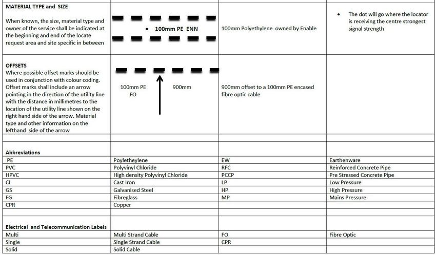
Copyright information
This publication is copyright © Waka Kotahi NZ Transport Agency (Waka Kotahi). Material in it may be reproduced
for personal or in-house use without formal permission or charge, provided suitable acknowledgement is made to
this publication and Waka Kotahi as the source. Requests and enquiries about the reproduction of material in this
publication for any other purpose should be made to:
Manager, Information
Waka Kotahi
Private Bag 6995
Wellington 6141
The permission to reproduce material in this publication does not extend to any material for which the copyright is
identified as being held by a third party. Authorisation to reproduce material belonging to a third party must be
obtained from the copyright holder(s) concerned.

Disclaimer
Waka Kotahi has endeavoured to ensure material in this document is technically accurate and reflects legal
requirements. However, the document does not override governing legislation. Waka Kotahi does not accept
liability for any consequences arising from the use of this document. If the user of this document is unsure whether
the material is correct, they should refer directly to the relevant legislation and contact Waka Kotahi.

This document is available on Waka Kotahi website at www.nzta.govt.nz

WAKA KOTAHI                                                        MINIMUM STANDARD FOR UTILITY IDENTIFICATION AND
                                                                                 PROTECTION ON ROAD PROJECTS // ii
Document management plan
Purpose
This management plan outlines the updating procedures and contact points for the document.
Document information
Amendments and review strategy
All corrective action/improvement requests (CAIRs) suggesting changes will be acknowledged by the document
owner.
COMMENTS FREQUENCY
Amendments
Updates incorporated immediately they occur. As required
(minor revisions)
Review Amendments fundamentally changing the content or structure of the
document will be incorporated as soon as practicable. They may Two yearly
(major revisions) require coordinating with the review team timetable.
Other information (at document owner’s discretion)
There will be occasions, depending on the subject matter, when amendments will need to be worked through by the
review team before the amendment is actioned. This may cause some variations to the above noted time frames.
WAKA KOTAHI MINIMUM STANDARD FOR UTILITY IDENTIFICATION AND
PROTECTION ON ROAD PROJECTS // iiiRecord of amendment
AMENDMENT NUMBER DESCRIPTION OF CHANGE EFFECTIVE DATE UPDATED BY
•
•
•
Acknowledgements
Key contributors included:
• James Mear | State Highway H&S Programme Manager – NZ Transport Agency
• Dave Bain | McConnell Dowell
• Ian Cox | New Zealand Utilities Advisory Group (NZUAG)
• ILM Forum | Powerco, Chorus, Water NZ, Civil Contractors, Enable, Rotorua Council
• Trevor Lord | Lord Civil
• Nick Gluvas | MWH
• Paula Lock | Opus
WAKA KOTAHI MINIMUM STANDARD FOR UTILITY IDENTIFICATION AND
PROTECTION ON ROAD PROJECTS // ivTable of Contents
Document management plan ...................................................................................................... iii
Record of amendment ................................................................................................................. iv
Acknowledgements ..................................................................................................................... iv
Table of Contents .......................................................................................................................... 1
1. INTRODUCTION ............................................................................................................................ 2
2.BACKGROUND ............................................................................................................................... 2
3.SCOPE ............................................................................................................................................ 2
4.BENEFITS OF A MINIMUM STANDARD FOR UTILITY IDENTIFICATION AND PROTECTION . 3
4.1 Improve safety for workers and others ................................................................................. 3
4.2 Avoid unexpected utility conflicts ......................................................................................... 3
4.3 Avoid damage to your brand and reputation ....................................................................... 3
5.COORDINATED APPROACH TO PLANNING AND APPLYING MINIMUM STANDARDS ........... 3
5.1 Responsibilities ....................................................................................................................... 3
5.2 Training and education ........................................................................................................... 4
5.3 Potential utility conflicts ......................................................................................................... 4
5.4 Strikes and consequences ..................................................................................................... 4
6.METHODS AND PROCESSES FOR LOCATING UTILITIES ......................................................... 4
6.1 Preferred methods for excavation ......................................................................................... 4
6.2 Processes for locating utilities .............................................................................................. 5
6.3 Planning for a site mark-out................................................................................................... 6
6.4 Marking out a site .................................................................................................................... 7
6.5 Use GPR to confirm target size ............................................................................................. 8
Appendix A: Responsibilities for identifying utilities ................................................................ 9
Appendix B: References ............................................................................................................. 11
Appendix C: Definition of Terms ............................................................................................... 12
Appendix D: Utility survey quality levels .................................................................................. 14
Appendix E: Utility mark-out standards ................................................................................... 16
Appendix F: Utility location briefing form ................................................................................ 17
Appendix G: Permit to excavate (example) .............................................................................. 20
Appendix H: Cable and pipe tracer features and specifications ............................................ 23
Appendix I: Ground penetrating radar (GPR) features and specifications ........................... 24
WAKA KOTAHI MINIMUM STANDARD FOR UTILITY IDENTIFICATION AND
PROTECTION ON ROAD PROJECTS // 11. INTRODUCTION
This document provides a minimum standard for utility identification and protection on road projects in New Zealand. It
has been produced by an industry working group representing utilities, contractors and designers.
In this document, you will read about:
• the benefits of using a minimum standard for utility identification
• a coordinated approach to application and planning
• methods and processes for locating underground utilities
• relevant measures for health, safety and the environment
2. BACKGROUND
Recent investigations into utility strikes and a Waka Kotahi workshop with key stakeholders found that the civil
construction industry has significant gaps in its approach to identifying and protecting utilities on road projects.
The current industry-wide approach to providing utility information and avoiding utility strikes is an issue for designers,
construction teams and utility network owners. This has a subsequent impact on safety, reputational and financial risk
to individual organisations and the community.
3. SCOPE
It is intended that this document complement rather than compete with existing utility procedures already in use in
New Zealand. Examples include New Zealand Utilities Advisory Group (NZUAG) National Code of Practice for Utility
Operators' Access to Transport Corridors, and WorkSafe NZ guidelines.
While the NZUAG Code of Practice, WorkSafe NZ guidelines and other New Zealand utility-specific regulations
provide a solid legislative framework, they do not provide detailed information on how best practice can be achieved.
The minimum standard for utility identification and protection applies to all those involved in the design process, and
to all phases of the design. It provides a focused approach that must be integrated into Waka Kotahi investigation,
design and construction processes. These minimum standards also apply to Waka Kotahi Network Outcomes
contracts.
This minimum standard document will:
• ensure every person working within a Waka Kotahi roading corridor and/or project area understands their role and
responsibilities in relation to health and safety and utilities
• provide processes to allow effective communication and coordination of utility related activities between asset
owners, designers and contractors
• define the process for ensuring the accurate mapping, location and depiction of utilities in three dimensions
• ensure all technical issues, timing and costs associated with utility design and construction are fully incorporated
into Waka Kotahi project scope and budget.
Waka Kotahi, along with the NZUAG and other New Zealand business partners, has the qualified personnel and
technology required to initiate this minimum standard without additional investment or the need to ‘reinvent the wheel’.
As part of the design process, consideration must be given to health and safety throughout the life cycle of the asset.
This includes reviewing how the asset can be constructed, operated, maintained, decommissioned or demolished
safely.
WAKA KOTAHI MINIMUM STANDARD FOR UTILITY IDENTIFICATION AND
PROTECTION ON ROAD PROJECTS // 24. BENEFITS OF A MINIMUM STANDARD FOR UTILITY
IDENTIFICATION AND PROTECTION
A minimum standard allows for the proactive and safe identification and protection of utilities that are located within
existing or proposed Waka Kotahi road corridors. An informed engineering design can then be carried out before
commencing project works.
The benefits include better safety, fewer utility conflicts, and protection of your brand and reputation.
4.1 Improve safety for workers and others
Accurate information about the location of utilities lets you keep excavation or grading work away from known utilities.
This minimises potential damage to the utility and reduces serious health and safety risks that may result in death,
personal injury, property damage, or releases of product into the environment.
4.2 Avoid unexpected utility conflicts
Conflicts and unsafe excavation can be avoided when construction plans accurately show the exact location of
utilities. This also reduces:
• project delays caused by redesign when construction can’t follow the original design due to utility conflicts
• construction delays caused by cutting, damaging, or discovering unidentified utility lines
• contractor claims for delays resulting from unexpected encounters with utilities.
Sometimes utilities are sited close to each other or interact with each other. This knowledge helps you highlight cost-
effective opportunities to make improvements.
4.3 Avoid damage to your brand and reputation
The repercussion of utility strikes can be significant when reported in media. When there are no utility strikes, the risk
to corporate, professional, or individual reputation can be avoided.
5. COORDINATED APPROACH TO PLANNING AND
APPLYING MINIMUM STANDARDS
A coordinated and systematic approach to minimum standards during the application and planning stages gives you
confidence in the location and depth of underground utilities before exposing or working around them. This reduces
potential strikes on utility networks.
This section describes:
• who is responsible for each part of the project
• what training and education to arrange before the project
• how to deal with potential utility conflicts you identify
• what to do if there is a utility strike.
5.1 Responsibilities
Everyone involved in the project has responsibilities throughout the project lifecycle:
• Programme business case and indicative business case – Transport Planners, Utility Operator and Design
Lead
• Detailed business case – Transport Planners, Project Manager, Designers and Utility Operator
• Pre-implementation – Project Manager, Designers, Corridor Access Manager and Utility Operator
• Implementation – Principal Contractor, Utility Operator, Engineer to Contract, Client Agent Manager and
Corridor Access Manager.
WAKA KOTAHI MINIMUM STANDARD FOR UTILITY IDENTIFICATION AND
PROTECTION ON ROAD PROJECTS // 3The table found in Appendix A sets out the responsibilities at each stage of the lifecycle.
5.2 Training and education
Before starting work on the site, project managers, site engineers, supervisors, operators, spotters, and all other staff
engaged on the project must be adequately trained and competent in:
• reading utility plans
• locating utilities
• health and safety matters relevant to the utilities they will be working around.
Training should be provided by a recognised industry professional. Daily site toolbox meetings must include the
procedures for locating, exposing and working around all utilities within the area covered by the permit to excavate.
5.3 Potential utility conflicts
If you identify a potential conflict during assessment or detailed design stages, confirm the utility locations with the
utility location providers. This will allow you to positively identify the utility and provide locations that are accurate to at
least Quality Level B as detailed in Appendix D.
Provide details of the protection, relocation or upgrade of affected utilities in the design report and construction
methodology as part of the project documentation.
All principal contractors, their subcontractors and all personnel employed or engaged by those parties must apply the
following procedures set out in this minimum standard.
5.4 Strikes and consequences
The person responsible (see Appendix A) must raise an incident report where a strike occurs on any utility. If any
processes or procedures have not been followed, the person responsible must also raise a non-compliance report.
Waka Kotahi must be promptly notified in writing following any utility strike (however it occurs).
Each principal contractor and its sub-contractors must undertake their own internal investigation following a utility strike.
They must keep Waka Kotahi updated on the progress of any such investigation. If requested, they must provide
copies of any reports to Waka Kotahi.
Each party is expected to have its own disciplinary procedures in place and to follow them in the event that conduct is
established that warrants disciplinary action.
If a utility is hit or compromised, or a notifiable event occurs, the delivery team and sub-contractor staff involved in the
event must undergo compulsory drug and alcohol testing.
A formal return-to-work process must follow any recordable utility strike, reportable utility incident, or notifiable event.
The project manager or their representative authorising the return to work must be satisfied that remedial action has
been taken and an investigation has been initiated.
6. METHODS AND PROCESSES FOR LOCATING UTILITIES
This document, together with Waka Kotahi minimum standard for hydro excavation, outlines the key considerations
required for efficient and cost effective hydro excavation and location by ground penetrating radar (GPR).This section
describes the:
• preferred methods for excavation
• processes for locating utilities
• planning for a site mark-out
• marking out a site.
6.1 Preferred methods for excavation
The work crew, led by the principal contractor’s project engineer, are responsible for making sure the appropriate
tools and methods for locating and working around underground utilities are used on their project.
WAKA KOTAHI MINIMUM STANDARD FOR UTILITY IDENTIFICATION AND
PROTECTION ON ROAD PROJECTS // 4Hydro or vacuum excavation is the preferred method for positively identifying utilities and working around utilities on
Waka Kotahi sites.
The project engineer should carry out a formal risk analysis when hydro or vacuum excavation is not practical.
Reasons not to hydro or vacuum excavate should be recorded in the Job Safety and Environmental Analysis (JSEA).
Permits should not generally allow machinery or hand digging within 1.5 metres of a utility that is indicated on a
drawing. If digging within 1.5 metres of a utility is necessary, the permit should require a formal risk analysis.
Use network-approved measures (such as ‘goalposts’ or ‘tiger tails’) to physically stop machines coming into contact
with any overhead lines.
Use engineered standard support and protection solutions for utilities that are exposed or fragile, particularly those
that span across or along trenches. This includes AC pipes and oil-filled electrical or telecommunication cables.
6.2 Processes for locating utilities
Use GPR or radio-frequency cable and pipe tracers to locate the utility indicated on a drawing. Hydro or air excavation
is the preferred methods to visually identify the utility. The project engineer should choose which method is most
appropriate.
Positively identify the utility and record its attributes before excavation begins within 1.5 metres of that utility - as
specified in the pre-dig documentation.
Locating underground utilities includes collating information from a range of sources. Check for information from all of
the following sources:
• surface observations such as marks, covers, trenches, depressions, or outlets
• building features relevant to termination of utilities
• visible utilities (such as drains in sumps), bollards of all types, lamp-posts, and hydrants
• anecdotal history of area (e.g. previous site uses, road widening evidence)
• Dial Before You Dig records for the site
• plans and records provided by the utility owners known to have underground utilities on the site
• detail provided by surface-based geophysical technologies including GPR, cable and pipe tracers, sondes,
pipe cameras, water hammer devices, ferrous-metal locators (for buried hatch covers), and hydraulic/vacuum
excavation.
The amount of information obtained from the above sources may vary depending on local site conditions and the
Quality Level required.
WAKA KOTAHI MINIMUM STANDARD FOR UTILITY IDENTIFICATION AND
PROTECTION ON ROAD PROJECTS // 56.3 Planning for a site mark-out
• Ensure the site requiring mark-out is clearly identified and that the required Quality
Level is defined before beginning work (refer Appendix D)
• Organise traffic management if required
• Plan for weather conditions - work is best carried out when there is no rain
• Obtain all plans and records before arriving on site (Dial Before You Dig)
• Review plans for completeness and confirm any details not clearly described (e.g. plan
scale or clutter at any given point) before arriving on site
• Consider appropriate survey pattern/strategy
• Plan for an optimum outcome by taking into account influencing local site conditions
(e.g. hilly terrain, uneven ground, known site issues)
• Assess all physical attributes and conduct a risk assessment
• Reconcile these with the details previously obtained to ensure completeness on site
arrival
WAKA KOTAHI MINIMUM STANDARD FOR UTILITY IDENTIFICATION AND
PROTECTION ON ROAD PROJECTS // 66.4 Marking out a site
• Confirm horizontal positions of (1) metallic assets using pipe and cable tracer, and (2)
non-metallic assets by laying tracer wires concurrently.
• Correlate positions with plans supplied.
• Confirm depths with GPR that delivers a clear location to a typical depth of two
metres and provides level of accuracy specified in utilities briefing form.
• Do not call depths with cable and pipe tracer unless cross-correlated with equipment
manufacturer’s recommended nulling technique.
• Enhance target clarity by ensuring survey depth window is nominally twice the
penetration depth.
• Signal strength of targets should be used to confirm or correlate target material (e.g.
metal vs non-metal).
• GPR survey pattern should cross all targets perpendicularly to ensure no errors in
depth readings.
• Ensure a cross-correlation with surface markers and identifying features for each
given utility type.
• If unknown targets are observed on a given trace, confirm by running parallel
sweeps at least one metre to each side to assess correlation of target line.
• Record relevant unusual underground features observed in the course of the survey
- with site report. These may include buried man-made targets such as flat-topped
surface features, covered tram tracks, slumpage, voids, or earthquake damage.
• Mark all identified targets on site to descriptors and colours as specified in Appendix
E, noting the Quality Level of any identifications not made to Quality Level B.
• Be aware of the risk of false targets when working with GPR near large trees.
• Review work against risk assessment and consider whether any changes to the
planned work or to the risk assessment are required.
WAKA KOTAHI MINIMUM STANDARD FOR UTILITY IDENTIFICATION AND
PROTECTION ON ROAD PROJECTS // 76.5 Use GPR to confirm target size
Use the GPR to confirm the actual target size conforms the target size expected. Remember to use the GPR in a
‘contextual’ fashion, observing signs of isolated trenches or disturbances with expected target location.
6.5.1 Record data obtained during a site mark out
Permanently mark all identified targets as described in Appendix E. Unless otherwise instructed, record them using
survey GPS to a resolution of +/- 100 mm (or better) in the horizontal plane. Record at a resolution of +/- 50mm (or
better) in the vertical and horizontal plane for utilities exposed in the location process.
The location contractor is responsible for ensuring the satellite coverage at the site is appropriate for the GPS survey
technique and that the data is recorded correctly.
Transfer saved GPS data to Waka Kotahi database within three working days of the mark-out.
6.5.2 Brief excavation crews before excavation
If excavation work will follow the location and mark out process, the location contractor must brief the project engineer
and site supervisor formally and fully on:
• the nature of the underground utilities
• the depths and positions of utilities (with accuracy statements on all points taken)
• special features of the site noted in the survey
• any unknown targets observed
• any other matters identified in the risk assessment.
The briefing must also include any control measures put in place to eliminate or minimise risks.
6.5.3 Operator requirements
A single operator is generally sufficient for a mark-out. Larger sites may require a second operator for improved
efficiency.
The project commissioner must be satisfied that the locate provider(s) is suitably qualified. All operators must provide
evidence of training in underground utility location by a recognised industry professional. If the locate is carried out for
design purposes, evidence must be provided to the project design lead. Alternatively if the locate is carried out as part
of construction, then evidence must be provided to the principal contractor’s project engineer.
In cases where more than one operator is required, the operators must consult and cooperate on assessing and
recording any risks and developing any relevant control measures.
WAKA KOTAHI MINIMUM STANDARD FOR UTILITY IDENTIFICATION AND
PROTECTION ON ROAD PROJECTS // 8Appendix A: Responsibilities for identifying utilities
•
•
•
•
•
•
•
•
•
•
•
•
•
•
• •
•
•
•
•
• •
•
•
•
• •
•
• •
•
•
•
• •
•
•
•
•
•
WAKA KOTAHI MINIMUM STANDARD FOR UTILITY IDENTIFICATION AND
PROTECTION ON ROAD PROJECTS // 9•
• •
•
•
•
•
•
•
•
•
•
•
•
•
•
•
•
WAKA KOTAHI MINIMUM STANDARD FOR UTILITY IDENTIFICATION AND
PROTECTION ON ROAD PROJECTS // 10Appendix B: References
The list of industry codes of practice and guides listed below are not comprehensive.
• TR Lord and Associates Ltd t/a LORD Civil
• LOCATE-SAFE® Buried utility location and identification method - brochure
• Waka Kotahi Survey specification Z-16: Z Series - State highway professional services contract proforma
manual
WAKA KOTAHI MINIMUM STANDARD FOR UTILITY IDENTIFICATION AND
PROTECTION ON ROAD PROJECTS // 11Appendix C: Definition of Terms
For the purpose of this document the following definitions apply:
• Utility location: The coordinated application of information on a given site from as many sources as possible, and
the marking out (to a range of prescribed tolerances) on the ground surface. The location process includes the
identification of the utility types expected at the site, and noting any other items that might also be of a utility
nature. The process provides for a range of confidences (Quality Levels) to be allocated to each item or cluster of
underground utilities, depending upon the nature of the information sources.
• Quality Levels: A series of four prescribed descriptions derived from Australian Standard AS5488: 2013 that have
been interpreted by Waka Kotahi to tighter tolerances of depth and positional accuracy from the various sources of
information for determining the final marked out location of underground utilities to a given confidence level (refer
Appendix D). The Quality Levels range from D to A, with the latter having the highest confidence levels in the
certainty of the depth, nature, and position of any underground infrastructure identified.
• Plans: The paper or electronic records of underground utilities for a given site. These plans are usually provided
by the owner/s of utilities at that site. The plans:
o may contain records of depth, route run, cross-sectional details, measurements off identified datum, and
depths
o are to be regarded only as guides to the location of the underground utilities to which they pertain
o must have been sourced from the asset owner within the past 30 days
o are generally obtained from the Dial Before You Dig service (0800 248 344).
• Ground penetrating radar (GPR): Is a device that is mounted on a wheeled cart structure in close proximity to
the surface of the ground. It contains at least a transmit antenna, a receive antenna, associated radar electronics,
an odometer to trigger the transmitting function at regular intervals, and a suitable display/controller device.
Typically the GPR uses frequencies between 250MHz (megahertz) to 1000 MHz. It can also be calibrated to
consider ground conditions and proved accurate depth information.
The GPR should be operated by a trained person who understands how to interpret the results from the survey in
the context of local conditions they observe, and by correlating the output with anticipated target shapes and
outlines.
• Pipe and cable tracer: A device to trace and determine the horizontal position of underground utilities of a metallic
nature. The device consists of two separate devices, a transmitter, and a receiver.
Each device will:
o Allow the use of at least two frequencies (1) a low frequency approx. 512 Hz or 815Hz to allow for physical
coupling to metallic items that are de-energised, and (2) a high frequency approx. 82 kHz (kilohertz) that is
used to induce signal into a metallic utility when placed above and parallel to it.
o Have transmitter powers in the range of 1-10 watts. The transmitter may also be equipped with a clamp-type
antenna as an option, allowing a nominal 82kHz signal to be induced into a specific utility, which the clamp
is placed around.
o A sonde, operating at 512 or 815 Hz, connected to a camera or drain rod and pushed up a pipe, may also
be used as the transmitting source.
WAKA KOTAHI MINIMUM STANDARD FOR UTILITY IDENTIFICATION AND
PROTECTION ON ROAD PROJECTS // 12• Mark-out: The recording on the ground surface at the nominated survey site of horizontal positions of all centre
lines corresponding to the horizontal position of each underground utility, along with a brief descriptor of each utility
type. Depth to the top of each utility can also be recorded.
o Marks on the ground are laid up in various colours of spray paint according to the guideline in Appendix E.
Indications of the extent of contiguous targets such as ducts laid by one asset owner can also be recorded in
the mark-out detail.
o If the final mark-out is being done for planning purposes significantly ahead of construction work, or if
specifically sought by Waka Kotahi, it can be recorded by manual use of a GPS unit having horizontal spatial
accuracy of +/100 mm or better (or +/- 50 mm in depth and position if working on Waka Kotahi Q/L B accuracy
mark out).
• Potholing: Digging one or more small-scale test holes to locate underground utilities to Quality Level A. Can be
completed using hydro or vacuum excavation, as opposed to careful hand digging.
WAKA KOTAHI MINIMUM STANDARD FOR UTILITY IDENTIFICATION AND
PROTECTION ON ROAD PROJECTS // 13Appendix D: Utility survey quality levels
This guideline is consistent with New Zealand regulation (NZUAG Code of Practice Oct 2011 and Utilities Access Act
2010), Australia Standard AS5488 (Draft) for Sub Surface Utility Information, and the USA’s ASCE 38-02 Standard
Guideline for the Collection and Depiction of Subsurface Utility Data. Section 2.8 of the NZUAG Code of Practice
contains the framework and New Zealand context for these requirements.
Quality Level D
Utility attribute information from Waka Kotahi GIS spatial viewer shall include:
a) utility owner,
b) an indication of the utility type, and
c) an indicative location of the visible and subsurface features of the utility. Tolerance does not apply to an indicative
location that is attributed to quality level D.
Quality Level C
Quality Level C is described as a surface feature correlation or an interpretation of the approximate location and
attributes of a subsurface utility asset using a combination of existing records (and/or anecdotal evidence) and a site
survey of visible evidence. The minimum requirement for Quality Level C is geospatial position in the local coordinate
system**.
Attribute information
Quality Level C attribute information shall include:
a) utility owner;
b) an indication of the utility type;
c) an interpolation of the location and direction of the subsurface utility using visible features or SURVEY
ACCURATE coordinates if available, as points of reference;
d) feature codes of visible features including but not limited to pits, access chambers, poles, valves and hydrants,
and
e) the location of visible features measured in terms of spatial positioning with a maximum horizontal tolerance of
±200 mm.
Quality Level B
Quality Level B provides relative subsurface feature location in three dimensions. The minimum requirement for
Quality Level B is geospatial position in the local coordinate system and datum**.
Attribute information
Quality level B attribute information shall include:
a) utility owner;
b) an indication of the utility type;
c) the location of visible features measured geospatially with a maximum horizontal tolerance of ±100 mm; and
d) the location of subsurface features measured geospatially with a maximum horizontal tolerance of ±100 mm and
maximum vertical tolerance of ±100 mm. Where there are contiguous utilities (e.g. a cluster of Chorus ducts) an
indication of the horizontal extent of these shall be recorded to a minimum of Quality Level C.
WAKA KOTAHI MINIMUM STANDARD FOR UTILITY IDENTIFICATION AND
PROTECTION ON ROAD PROJECTS // 14Quality Level A
Quality Level A is the highest quality level and consists of the positive identification of the attribute and location of a
subsurface utility at a point to absolute geospatial accuracy in three dimensions. It is the only quality level that defines
a subsurface utility as ‘validated’.
Where the whole line segment cannot be verified by line of sight, Quality Level A shall not be attributed to the line
segment between validated points.
Attribute information
Quality Level A attribute information shall include:
a) utility owner;
b) the utility
Type
Status (in service or unknown)
Material
Size, and
configuration
c) feature codes of visible and subsurface features including but not limited to pits, access chambers, poles, valves,
hydrants; and
d) the location of points surveyed on visible surface and subsurface features measured in terms of absolute spatial
positioning with a maximum horizontal and vertical tolerance of ±50 mm
Local Coordinate System Waka Kotahi: New Zealand Geodetic Datum 2000 – Local projection (as relevant to each
project area)
Local Vertical Datum Waka Kotahi: Local Datum
**
WAKA KOTAHI MINIMUM STANDARD FOR UTILITY IDENTIFICATION AND
PROTECTION ON ROAD PROJECTS // 15Appendix E: Utility mark-out standards
Service COLOUR Network Operator Marking Convention
(Examples)
Electrical, lighting, traffic signals ORANGE
Lines, cables and ducting Electricity ORN
Street lights and Traffic Signals CCC
Telecommunications
Lines, cables and ducting Telecom/Chorus (CHOR) CHOR
PURPLE
CHORUS
Vodafone VOD)
VOD
Vodafone
Ultra-fast broadband PURPLE
Fibre optic cables UFB Operator UFB
YELLOW GAS GAS
Gas
Potable water BLUE
Water Authority H2O
Wastewater RED
Wastewater Authority WW
Stormwater GREEN Stormwater Authority SW
Preliminary mark out All services for preliminary design or Must use colour codes for construction mark out –
(Not for construction) White investigation only No exceptions
WAKA KOTAHI MINIMUM STANDARD FOR UTILITY IDENTIFICATION AND
PROTECTION ON ROAD PROJECTS // 16Appendix F: Utility location briefing form
Project ID Your project ID here 10XXX
Project Name Your project name/description here
From Type your name here
Contact Details Type your desk and mobile phone numbers here
Date Type date here
Requested Due Date Type date information is required by. Be realistic!
Project Purpose Expand
Deliverables Clarify format data is returned in; eg 12d file, excel sheet with xyz, CAD file
hand drawn sketch, photographs, etc
Known issues? eg fuel pipeline, level 2 road, Waka Kotahi road, private access required,
known site contact (provide contact details), etc
References
WAKA KOTAHI MINIMUM STANDARD FOR UTILITY IDENTIFICATION AND
PROTECTION ON ROAD PROJECTS // 17Quality level
Utility attribute information shall include:
A B C D
1. utility owner ✓ ✓ ✓ ✓
2. indication of the utility type ✓ ✓ ✓ ✓
3. indication of the utility status (in service or unknown) ✓
4. indication of the utility material ✓
5. indication of the utility size ✓
6. indication of the utility configuration ✓
7. indicative location of the visible and subsurface features of the
utility ✓ ✓
8. interpolation of the location and direction of the subsurface utility
using visible features or GPS coordinates if available, as points of ✓
reference
9. feature codes of visible features including but not limited to pits,
access chambers, poles, valves and hydrants ✓ ✓ ✓
10. the location of visible features measured in terms of spatial
positioning with a maximum horizontal tolerance of 50mm 100mm 200mm NA
11. feature codes of visible and subsurface features including but not
limited to pits, access chambers, poles, valves, hydrants ✓ ✓
12. subsurface feature vertical tolerance 50mm 100mm NA NA
13. subsurface feature horizontal tolerance 50mm 100mm 200mm NA
Note: Quality Level A is the highest quality level and consists of the positive identification of the attribute and location
of a subsurface utility at a point to an absolute accuracy in three dimensions. It is the only quality level that defines a
subsurface utility as ‘validated’. Where the whole line segment cannot be verified by line of sight, Quality Level A
shall not be attributed to the line segment between validated points.
WAKA KOTAHI MINIMUM STANDARD FOR UTILITY IDENTIFICATION AND
PROTECTION ON ROAD PROJECTS // 18Location ID #1 Street House # Type of utility targeted: Original or make Quality Level Notify Engineer Other i.e. different level
e.g. pressure main, safe pavement A/B/C when digging of accuracy (state) etc.
laterals, all, etc O/M Y/N
10999-PH-001 Magdala Place 1 lateral O A N
10XXX-PH-001
10XXX-PH-002
10XXX-PH-003
10XXX-PH-004
10XXX-PH-005
10XXX-PH-006
10XXX-PH-007
10XXX-PH-008
10XXX-PH-009
10XXX-PH-010
10XXX-PH-011
10XXX-PH-012
10XXX-PH-013
10XXX-PH-014
In addition, a clearly annotated proposed plan must also be attached and contain the following information:
• project name and project number
• street addresses and house numbers
• all known utilities shown
• clearly marked location of the proposed pothole and/or scan areas
• the type of the proposed investigation works (laterals, mains, etc).
11Note: Typical pothole ID# format: 10XXX-PH-YYY, where 10XXX is the project number (Waka Kotahi assigned) and YYY is the sequential counter,
starting at 001.
WAKA KOTAHI MINIMUM STANDARD FOR UTILITY IDENTIFICATION AND
PROTECTION ON ROAD PROJECTS // 19Appendix G: Permit to excavate (example)
Waka Kotahi Agency Project No _______________________
Waka Kotahi Project Name _______________________
SITE COPY / OFFICE COPY (circle one)
Construction Contractor: PERMIT No:
Permit request
Location of excavation (clearly identify boundary of excavation area):
Description/purpose of excavation:
Name of contractor/subcontractor:
Start date of work:
Permit expiry date:
Is the work notifiable? ❑ Yes ❑ No (If yes send notification to healthsafety.notification@worksafe.govt.nz)
• Will work be within 1.5 metres of any underground utility? ❑ Yes ❑ No
• Will work be within 4 metres of overhead lines? ❑ Yes ❑ No
• Within minimum safe distances for excavation near poles or stay wires (5 metres)? ❑ Yes ❑ No
(New Zealand Electrical Code of Practice for Electrical Safe Distances (NZECP 34:2001)
• Are there gas mains within 5 metres of the works? ❑ Yes ❑ No
• Is there fibre optic cable within 5 metres of the works? ❑ Yes ❑ No
• Are there traffic signals within 50 metres of the works? ❑ Yes ❑ No
Underground utilities
Approval to work attached and stand over by electrical network arranged for 66Kv, 33Kvor 11Kv on site? ❑ Yes ❑ N/A
Any requirements/safeguards to be observed:
Telecommunication approval issued in regards to within 5 metres of fibre optic cable and attached? ❑ Yes ❑ N/A
Any requirements/safeguards to be observed:
Gas provider contacted in regards to work within 5 metres of gas mains ❑ Yes ❑ N/A
Any requirements/safeguards to be observed:
Traffic Signals team contacted in regards to work within 50m of traffic signals ❑ Yes ❑ N/A
WAKA KOTAHI MINIMUM STANDARD FOR UTILITY IDENTIFICATION AND
PROTECTION ON ROAD PROJECTS // 20Overhead utilities
Approval to work within 4 metres of overhead lines or 5 metres of poles and stay wires issued by electricity network and attached?
❑ Yes ❑ N/A
Any requirements/safeguards to be observed:
New Zealand Electrical Code of Practice for Electrical Safe Distances (NZECP 34:2001
WorkSafe NZ
WorkSafe NZ (www.business.govt.nz/worksafe/) notified? ❑ Yes ❑ N/A
Service plans / utility as builts
Service plan expiry date (30 days from date of issue):
Service plans obtained by: Signature: Date:
Permit issued to: Signature: Date:
Permit authorised by: Project Manager Signature: Date:
Handover person: Signature: Date:
Utility location
Traced and marked by: Signature: Date:
Company:
Comments:
Excavation pre-start
As the person responsible for the above mentioned work, I will inform all associated personnel bound by this Permit of their duties and ensure compliance
site specific excavation requirements as stated in the JSEA.
Site Engineer: Signature: Date:
I will undertake non-destructive pot-holing to visually identify all utilities shown in this permit prior to works commencing.
(refer Excavation procedure agreement)
Subcontractor Foreman: Signature: Date:
Excavator Operator: Signature: Date:
WAKA KOTAHI MINIMUM STANDARD FOR UTILITY IDENTIFICATION AND
PROTECTION ON ROAD PROJECTS // 21Permit extension (if required)
Works still within boundaries of the existing permit: ❑ Yes ❑ No (If no request a new permit)
Service plans still valid (no other contractors have moved or added utilities within site)? ❑ Yes ❑ No
Permit extended to: Authorised by: Signature:
Permit close out
Job complete and site left secure and safe ❑ Yes ❑ No
Service plans withdrawn from site and discarded or archived ❑ Yes ❑ No
Closed out by: Site Engineer Signature: Date:
Excavation Procedure Agreement
The below procedure must be followed when working around utilities on Waka Kotahi sites.
1. Where a utility locate provider has been used, site engineer must walk over site with the locate provider to review
their findings.
2. Site engineer and subcontractor’s supervisor/foreman to confirm that utility plan and that any utilities marked
onsite are in agreement
3. Contractor is responsible for contacting site engineer at least two hours prior to excavation works
commencing.
4. All underground utilities must be potholed by hydro or air excavation, hand excavation, or a combination of
both. Pick axes and crow bars must not be used except for breaking up surface seal.
5. All utilities found by potholing must be visually identified as the utility that is on the drawing.
6. No mechanical excavator is allowed to work within 2 metres of a utility if it has not been potholed and
positively identified by an engineer and subcontractor foreman/spotter.
7. An engineer must be present when any excavation work takes place around electrical cables, gas lines or
fibre optic cables.
8. When excavating close to any underground utility, a competent spotter must be present to guide the
excavator operator, after it has been potholed.
9. When working close to overhead lines a competent spotter must be present to guide the excavator operator.
If the spotter needs to step away, the excavator must stop work until the spotter returns.
10. Where appropriate, ‘tiger tails’ will be fixed to overhead lines. The electricity network will make an
assessment on whether ‘tiger tails’ are appropriate.
11. Where possible, overhead lines may be relocated temporarily.
Waka Kotahi, Principal Contractor:
Failure to follow these procedures may result in disciplinary action being taken against the individual/s
responsible.
Subcontractors:
Failure to follow these procedures will result in excavator operator and spotter being re-inducted. Repeat
offenders will be removed from site.
Subcontractor’s representatives (Foreman and Operator):
Signed: Signed:
Date: Date:
Principal Contractor representative
Signed:
Date:
WAKA KOTAHI MINIMUM STANDARD FOR UTILITY IDENTIFICATION AND
PROTECTION ON ROAD PROJECTS // 22Appendix H: Cable and pipe tracer features and specifications
There is a range of technology available in an extensive variety of packages. The professional location
contractor should include the following minimum requirements in the package:
• Transmitter with a power of at least 5 watts, preferably 10 watts, capable of maintaining this into a direct
connection impedance of 10 kilohms. The transmitter power setting should be adjustable.
• Transmitter frequencies of at least 815Hz and 82 kHz, but possibly including other frequencies such as 8
kHz and 33 kHz.
• 100 mm clamp-style antenna accessory and direct-connect leads, and earth stake accessory.
• Ample supply of transmitter batteries for the day or a rechargeable transmitter.
• Receiver with the frequency capability to match the above transmitter, and additional modes of 50Hz and RF.
• Push-button depth modes on receivers are an option but should not be used to determine depths formally.
WAKA KOTAHI MINIMUM STANDARD FOR UTILITY IDENTIFICATION AND
PROTECTION ON ROAD PROJECTS // 23Appendix I: Ground penetrating radar (GPR) features and specifications
To allow the best combination of penetration depth and identification of weaker reflecting targets (e.g. air-filled
ducts), all surveys carried out must be at a frequency that provides the levels of accuracy specified in Appendix
D.
Ideally the GPR antenna should be shielded to minimise the effects of surrounding surface features. As different
frequencies offer an advantage in data clarity, the operating frequency of the equipment should be optimised
according to the locate requirements.
GPR units must have practical, quick, and simple to use onscreen means to confirm the propagation speed of
the GPR signal in ground at every point at which a depth reading is taken.
Ideally the operator should be able to set depth ranges and gain on the GPR display. This should be adjustable
in real time without having to re-trace the surveyed data once a change has been made.
A filter to remove horizontal stratigraphy on the display is a useful feature.
While trace recording is not required for Waka Kotahi locations, the facility to save and later download a given
underground feature noted by the operator is encouraged. Associated fudicial marks on the display are an
advantage.
WAKA KOTAHI MINIMUM STANDARD FOR UTILITY IDENTIFICATION AND
PROTECTION ON ROAD PROJECTS // 24You can also read