A Low Cost Approach to Disturbed Soil Detection Using Low Altitude Digital Imagery from an Unmanned Aerial Vehicle - MDPI
←
→
Page content transcription
If your browser does not render page correctly, please read the page content below
drones
Article
A Low Cost Approach to Disturbed Soil Detection
Using Low Altitude Digital Imagery from an
Unmanned Aerial Vehicle
Elizabeth Parrott 1, * , Heather Panter 2 , Joanne Morrissey 3       and Frederic Bezombes 1
 1   Faculty of Engineering and Technology, Liverpool John Moores University, James Parsons Building,
     Byrom Street, Liverpool L3 3AF, UK; f.bezombes@ljmu.ac.uk
 2   Liverpool Centre for Advanced Policing, Liverpool John Moores University, John Foster Building,
     80-98 Mount Pleasant, Liverpool L3 5UZ, UK; h.a.panter@ljmu.ac.uk
 3   School of Life Sciences, Faculty of Science and Engineering, Anglia Ruskin University, East Road,
     Cambridge CB1 1PT, UK; joanne.morrissey@anglia.ac.uk
 *   Correspondence: e.parrott@2012.ljmu.ac.uk

 Received: 9 May 2019; Accepted: 19 June 2019; Published: 21 June 2019

 Abstract: Until recently, clandestine burial investigations relied upon witness statements to determine
 target search areas of soil and vegetation disturbance. Due to this, remote sensing technologies are
 increasingly used to detect fresh clandestine graves. However, despite the increased capabilities of
 remote sensing, clandestine burial searches remain resourcefully intensive as the police have little
 access to the technology when it is required. In contrast to this, Unmanned Aerial Vehicle (UAV)
 technology is increasingly popular amongst law enforcement worldwide. As such, this paper explores
 the use of digital imagery collected from a low cost UAV for the aided detection of disturbed soil sites
 indicative of fresh clandestine graves. This is done by assessing the unaltered UAV video output using
 image processing tools to detect sites of disturbance, therefore highlighting previously unrecognised
 capabilities of police UAVs. This preliminary investigation provides a low cost rapid approach to
 detecting fresh clandestine graves, further supporting the use of UAV technology by UK police.

 Keywords: forensic science; unmanned aerial vehicle; clandestine burial; grave detection; airborne;
 image processing; policing

1. Introduction
     For the purposes of this study, a clandestine burial will be defined as the intentional concealment
of complete or partial human remains, usually a victim of homicide [1]. With this in mind, the most
common methods of body disposal include; covering (31.4%), burying (21%) and leaving in isolated
places (14.2%) [2]. A study of 29 UK clandestine burial cases shows that clandestine burials are
usually less than one metre deep and constructed using common garden tools [3]. Consequently,
these fresh graves appear rushed, haphazard and visible due to characteristic disturbance of soils and
vegetation [3–7].
     Previous researchers of clandestine burials [8] have used a two-fold search process to determine
grave location. A two-fold search process firstly relies upon crucial planning and intelligence to
determine a target search area to locate visual anomalies. This is to ensure secondary search methods,
such as line searches [9], cadaver dogs [10], probing [7] and geophysical techniques such as Ground
Penetrating Radar (GPR) [11–17], are more efficient and cost effective [5,18].
     Yet, current methods of clandestine burial searches remain costly as police resources are spent on
determining grave location guided by witness statements [4,12,19]. Due to this, state-of-the-art remote
sensing techniques such as aerial photography using Unmanned Aerial Vehicles (UAVs) are replacing

Drones 2019, 3, 50; doi:10.3390/drones3020050                                    www.mdpi.com/journal/drones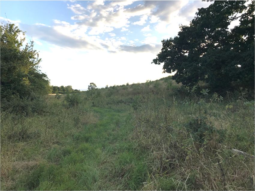
Drones 2019, 3, 50                                                                                  2 of 12

the reliance upon witness statements by determining the approximate grave location through the rapid
detection of visual anomalies [18,20,21]. In this context, remote sensing is the acquisition of data about
an object or scene without physically touching it [22].
      Current remote sensing techniques used in the search for clandestine graves include the use of
sensors mounted on-board satellites, manned aircraft and UAVs, for the purpose of capturing imagery
or collecting other data for analysis [20]. Satellite imagery is the most traditional remote sensing
technique used to detect ground disturbance [23], previously, satellite imagery has been used with
success to detect burials in mass grave scenarios [19,24,25]. However, more suited for identifying single
clandestine burials is the use of full-scale manned aircraft to provide real-time aerial photography due
to the reduction of cloud cover compared to satellite imagery. Within an archaeological context, aerial
photography from manned aircraft is an established technique used to record sites of disturbance
and/or capture visual anomalies [26–28]. Common successful approaches include the use of invisible
near infrared (NIR) photography to capture anomalies caused by potential buried material [29–31].
Although airborne hyperspectral imaging may be useful from a spectral point of view, the data still
lack the necessary spatial resolution (4.7–5.2 m) to detect single targets [19]. However, whilst the image
resolution obtained from full-scale aircraft is often much better suited compared to satellites, manned
aircraft are still operationally costly and access is limited amongst law enforcement agencies. Despite
these limitations, in an investigative context, airborne systems are still more commonly favoured over
traditional geophysical techniques [32] as they limit unnecessary footfall, which minimizes crime scene
alteration [20].
      In contrast to this, UAV technology has gained popularity amongst law enforcement agencies
as a low cost aerial support tool [33,34]. Due to its capability for fast deployment with limited
demands upon police resources. While the literature surrounding the use of UAVs for clandestine
burial detection is generally limited [20,21,35], questions have been raised regarding their practical
usage in large scale homicide investigations, with regards to the detection of buried remains. As such,
Murray et al. (2018) have written an exhaustive review on the use of the use of UAVs and multiple
sensors for the detection of clandestine graves and surface remains [21]. With regard to this, current
UAV clandestine burial detection methods only extend the reach of the traditional photographer
without improving efficiency [33], as these approaches still require the manual analysis of every
captured image or significant computation to undergo convolutional neural network or deep learning
approaches. In addition, these previous approaches have required specific image capture devices
and modified or custom UAV payloads, unlike the unmodified common commercial systems (e.g.,
DJI Mavic, Phantom, and Inspire Series) which have been purchased within UK policing. As such,
the method outlined in this paper uses a standard commercial UAV system (DJI F550 Flame-wheel),
equipped with an unmodified Red-Green-Blue (RGB) camera and video processing algorithm to
determine whether an unmodified UAV, equivalent to UK police systems, can be used as a low cost tool
for the aided detection of disturbed soil sites on shrub and grasslands, indicative of fresh clandestine
burials. With the overall aim of improving operational productivity of shallow grave and clandestine
burial searches.
      Crucially, this approach uses a non-invasive visual based search method, that is comparably
low-cost (£700) to other remote sensing techniques (e.g., hyperspectral imaging £5000–£100,000 or
laser scanning £30,000+), with the ability to also adopt an exclusionary search approach [18,36,37].
The intention is not to replace the investigator or forensic professional, but to reduce demands upon
resources and increase efficiency, by introducing new technology alongside established techniques.
Ultimately, the physical analysis of the disturbed soil sites will remain the task of the practitioner,
however; the proposed process used in this study highlights how the initial search process can become
less resourcefully intensive.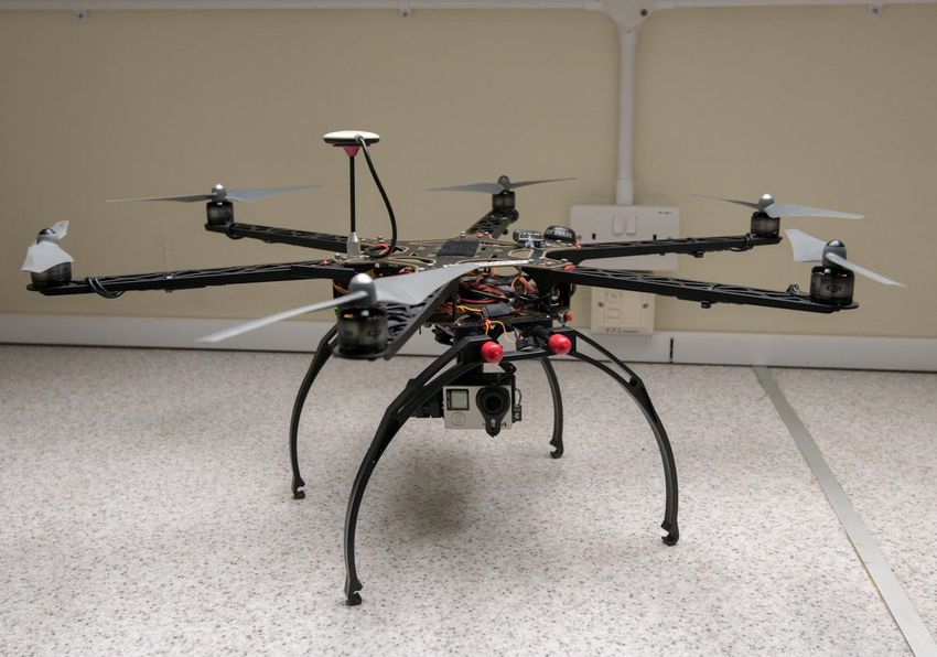
Drones 2019, 3, 50 3 of 12
Drones 2019, 3, x FOR PEER REVIEW 3 of 13
2. Materials
2. Materials and Methods
and Methods
2.1. Study Site
A large area of isolated grass and shrub land south of Chester, England
England was selected as the study
site. This area of land consists of a clay
site. clay rich
rich soil
soil covered
covered by
by dense
dense shrub
shrub land,
land, trees
trees and
and aa small
small stream.
stream.
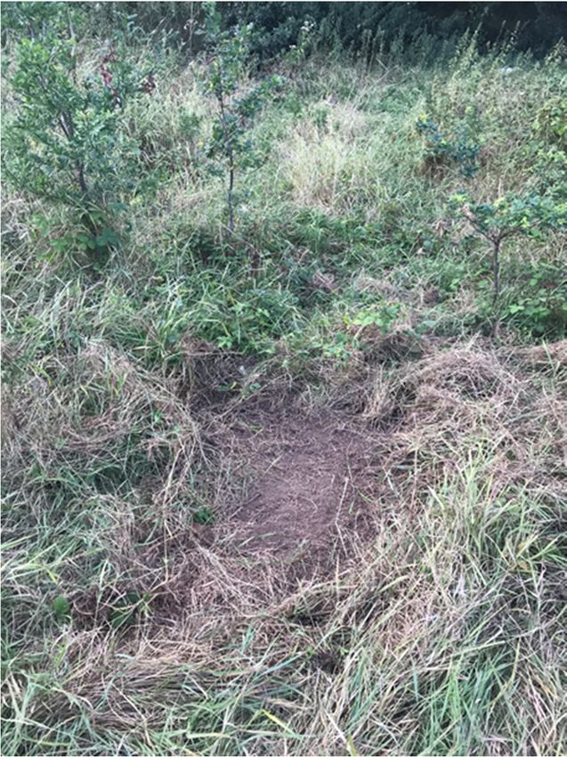
The vegetation
The vegetation was
wasover
over11mmtall
tallin
insome
someparts
partsmaking
makingthe
thegrave
graveobscured
obscuredfrom
fromline
lineofofsight
sight even
even atat
a
a small distance during a traditional foot search (Figure
small distance during a traditional foot search (Figure 1). 1).
Figure
Figure 1. A photograph
1. A photograph taken
taken standing
standing alongside
alongside the
the simulated
simulated grave
grave position.
position.
An
An approximate
approximate1 1mm square patch
square of land
patch was selected
of land randomly
was selected withinwithin
randomly this testthis
sitetest
and site
roughly
and
dug over using a common garden shovel, to simulate the presence of a recent clandestine
roughly dug over using a common garden shovel, to simulate the presence of a recent clandestine burial
(Figure 2). No human
burial (Figure 2). Noor animalor
human material
animalwas placedwas
material into placed
the simulated grave
into the due to the
simulated Human
grave due Tissue
to the
Act (2004) and restrictions from the landowner. The use of a common garden shovel
Human Tissue Act (2004) and restrictions from the landowner. The use of a common garden shovel and approximate
m2 approximate
1and simulated grave1 mwas to replicate
2 simulated thewas
grave visual appearance
to replicate theofvisual
clandestine burials
appearance ofoutlined
clandestinein analyses
burials
of 29 UK cases [3].
outlined in analyses of 29 UK cases [3].Drones 2019, 3, 50 4 of 12
Drones 2019, 3, x FOR PEER REVIEW 4 of 13
Figure 2. The simulated grave site partially recovered with disturbed
recovered with disturbed vegetation.
vegetation. Approximately m22
Approximately11 m
in size.
2.2. UAV Platform
2.2. UAV Platform and
and Data
Data Capture
Capture
A
A DJI F550 Flame-wheel
DJI F550 Flame-wheel hexacopter
hexacopterequipped
equippedwith
withan
anunmodified
unmodifiedRGB RGBcamera
cameracontrolled
controlledbyby a
agimbal
gimbal was used to capture all of the airborne video data (Figure 3). The DJI F550
was used to capture all of the airborne video data (Figure 3). The DJI F550 Flame-wheel Flame-wheel is a
is a commercially
commercially available
available UAVUAV kit measuring
kit measuring 550 diagonally
550 mm mm diagonally
across,across,
with awith a frame
frame weightweight
of 478 of
g,
478 g, and a maximum take-off mass of 2400 g [38]. The DJI F550 Flame-wheel was
and a maximum take-off mass of 2400 g [38]. The DJI F550 Flame-wheel was equipped with a DJI equipped with a
DJI Naza M V2 flight controller connected to a global positioning system (GPS)
Naza M V2 flight controller connected to a global positioning system (GPS) module and power module and power
management unit (PMU).
management unit (PMU). TheThe propulsion system consisted
propulsion system consisted of
of six
six DJI
DJI 2312E
2312E 920
920 kV
kV motors
motors and
and six
six
DJI E420 electronic speed controllers (ESCs). The UAV was powered with a 14.8 V (four
DJI E420 electronic speed controllers (ESCs). The UAV was powered with a 14.8 V (four cell) Lithiumcell) Lithium
Polymer
Polymer battery and remotely
battery and operated via
remotely operated via an
an FrSky
FrSky Taranis
Taranis X9D
X9D 2.4
2.4 GHz
GHz Transmitter
Transmitter bound
bound to to aa
FrSky
FrSky X8R
X8R Receiver. The propellers
Receiver. The propellers fitted
fitted to
to the
the UAV
UAV were
were self-tightening
self-tightening DJI
DJI 9443 9-inch propellers.
9443 9-inch propellers.
A GoPro Hero 4 (Black Edition) was mounted to the UAV using a Tarot 2-axis brushless gimbal
to ensure image stabilisation. The gimbal also allowed for the manual angular positional control
of the camera during flight using the pilot’s transmitter to obtain views from selected angles and
orientations. During image acquisition, the gimbal was kept positioned parallel to the ground to
obtain good coverage of the search area. For all data capture, the GoPro video footage was captured at
25 frames per second (fps) in protune mode at a 4 K (3840 × 2160) resolution and all the video footage
was recorded in approximately four and a half minutes. Initially, a separate test flight was conducted
to capture a calibration image of a disturbed soil site within the survey area, to obtain comparative
threshold values to compare to potential visual anomalies discovered during data capture within the
target area. To conduct data collection the UAV was manually flown at altitudes of approximately
2, 5, 10 and 20 m above ground level (AGL) in raster patterns over the search area to maximise the
site coverage and capture data for analysis. Although in the UK the UAV could be flown up to 400 ft
according to Civil Aviation Authority (CAA) legislation [39], these altitudes were selected to provide a
broad dataset and examine the algorithm performance at different flying heights, whilst still beingDrones 2019, 3, 50 5 of 12
able to cover large areas. The data capture was conducted during the British summertime in the late
afternoon;
Drones 2019, 3,weather conditions
x FOR PEER during the image acquisition were dry but overcast.
REVIEW 5 of 13
Figure 3.
Figure DJI F550
3. DJI F550 Flame-wheel
Flame-wheel drone
drone with
with gimbal
gimbal and
and camera
camera used
used for
for data
data collection.
collection.
2.3. Video Processing
A GoPro Hero 4 (Black Edition) was mounted to the UAV using a Tarot 2-axis brushless gimbal
The data
to ensure image processing was performed
stabilisation. The gimbal using
alsoMATLAB version
allowed for R2017b angular
the manual and functions from control
positional the image of
processing
the 2019, 3,and
camera
Drones computer
during
x FOR flight
PEER vision
using toolboxes.
REVIEW the pilot’sAn overview to
transmitter of the algorithm
obtain views is included
from in Figure
selected angles4.6and
of 13
orientations. During image acquisition, the gimbal was kept positioned parallel to the ground to
obtain good coverage of the search area. For all data capture, the GoPro video footage was captured
at 25 frames per second (fps) in protune mode at a 4 K (3840 × 2160) resolution and all the video
footage was recorded in approximately four and a half minutes. Initially, a separate test flight was
conducted to capture a calibration image of a disturbed soil site within the survey area, to obtain
comparative threshold values to compare to potential visual anomalies discovered during data
capture within the target area. To conduct data collection the UAV was manually flown at altitudes
of approximately 2, 5, 10 and 20 m above ground level (AGL) in raster patterns over the search area
to maximise the site coverage and capture data for analysis. Although in the UK the UAV could be
flown up to 400 ft according to Civil Aviation Authority (CAA) legislation [39], these altitudes were
selected to provide a broad dataset and examine the algorithm performance at different flying
Figure 4. A basic overview of the video processing algorithm used for disturbed soil detection.
heights,Figure
whilst4.still
A basic
beingoverview of the video
able to cover processing
large areas. The algorithm usedwas
data capture for disturbed
conducted soil detection.
during the British
summertime in the late afternoon; weather conditions during the image acquisition
Before completing the workflow outlined within Figure 4, a still image was selected from were dry but
the
Before completing the workflow outlined within Figure 4, a still image was selected from the
overcast.
test flight to obtain comparative threshold values for all subsequent video processing, this process
test flight to obtain comparative threshold values for all subsequent video processing, this process
assessed and recorded the colour components of the CIE 1976 L*a*b* colourspace [40] within the test
assessed
2.3. Video and recorded the colour components of the CIE 1976 L*a*b* colourspace [40] within the test
Processing
flight video frame. All subsequent analysis was then completed using these obtained threshold values
flight video frame. All subsequent analysis was then completed using these obtained threshold
as follows
The data(Figure 4); the video
processing was was uploaded
performed intoMATLAB
using the MATLAB workspace
version R2017band anda functions
single imagefromframe
the
values as follows (Figure 4); the video was uploaded into the MATLAB workspace and a single image
was extracted and stored in the workflow as a 2D array. Next, the motion blur was
image processing and computer vision toolboxes. An overview of the algorithm is included in Figure removed from the
frame was extracted and stored in the workflow as a 2D array. Next, the motion blur was removed
image by de-interlacing the single frame. The image colour space was converted from RGB to the CIE
4.
from the image by de-interlacing the single frame. The image colour space was converted from RGB
1976 L*a*b*colourspace, which is a numerical colour representation of the image colour space where L*
to the CIE 1976 L*a*b*colourspace, which is a numerical colour representation of the image colour
is Lightness and a* and b* are respectively the green-red and blue-yellow colour components. The CIE
space where L* is Lightness and a* and b* are respectively the green-red and blue-yellow colour
1976 L*a*b* colourspace was used as during development it distinguished the most difference between
components. The CIE 1976 L*a*b* colourspace was used as during development it distinguished the
the simulated grave site and surrounding vegetation. The three-channel threshold determined from
most difference between the simulated grave site and surrounding vegetation. The three-channel
threshold determined from the test flight data was applied to the image resulting in a binary (bit)
mask. The resulting bit mask was then eroded (Speckle noise filtering, Figure 4) to remove any
speckle noise of less than three pixels in diameter, this ensured only larger objects in the mask more
likely to be graves remained and smaller noise artefacts were discarded. Then the size and positionDrones 2019, 3, 50 6 of 12
the test flight data was applied to the image resulting in a binary (bit) mask. The resulting bit mask
was then eroded (Speckle noise filtering, Figure 4) to remove any speckle noise of less than three pixels
in diameter, this ensured only larger objects in the mask more likely to be graves remained and smaller
noise artefacts were discarded. Then the size and position of any remaining objects in the bit mask
were assessed and noted. If after filtering, no objects were discovered the next image was assessed.
Otherwise, a red bounding box was drawn over the disturbed soil site in the original image. This
entire process was encompassed within a loop to sequentially analyse images every 12 frames, a time
interval equivalent to approximately 0.5 ms one after another.
3. Results
To ensure all results were equally comparable, the algorithm parameters were not changed during
the course of the experiment and so the analysis of every image was identical. Consequently, the
disturbed soil site was highlighted and detected successfully across the video where the simulated
gravesite was present in the image frame. Figures 5–9 show this successful detection of the same grave
location selected randomly from different perspectives and altitudes extracted at different points in the
dataset. Use of a gimbal mounted underneath the UAV enabled the camera to be positioned facing
downwards, to ensure that the gravesite was recorded directly from above without obstruction from tall
vegetation and excessive motion blur. Erosion of speckle noise within the image was essential to lower
the likeliness of false positives from small-misinterpreted objects in the camera view; consequently, no
false
Dronespositives were
2019, 3, x FOR identified
PEER REVIEW within the datasets. 7 of 13
Figure
Figure 5. An example
5. An example algorithm
algorithm output
output image
image with
with the
the disturbed
disturbed soil
soil site
site detected
detected in
in the
the lower
lower right
right
region of the image. Recorded at an altitude of approximately 10 m above ground
region of the image. Recorded at an altitude of approximately 10 m above ground level (AGL). A level (AGL). A stream
can be seen
stream can on
be the leftonhand
seen the side of theside
left hand image
of and
the aimage
faint vehicle trackway
and a faint running
vehicle top torunning
trackway bottom top
across
to
the image is visible on the left side of the disturbed soil site.
bottom across the image is visible on the left side of the disturbed soil site.Figure 5. An example algorithm output image with the disturbed soil site detected in the lower right
region of the image. Recorded at an altitude of approximately 10 m above ground level (AGL). A
Dronesstream
2019, 3, can
50 be seen on the left hand side of the image and a faint vehicle trackway running top to7 of 12
bottom across the image is visible on the left side of the disturbed soil site.
Figure
Figure 6. 6. An example
example algorithm
algorithmoutput
outputimage
imagewith
withthe
thedisturbed
disturbedsoil
soilsite detected
site within
detected within thethe
centre of
centre
the image. Recorded at an altitude of approximately 15 m AGL. A stream can be seen
of the image. Recorded at an altitude of approximately 15 m AGL. A stream can be seen on the left on the left hand
side of the of
imageimage
and a and
faintavehicle trackway running top to top
bottom across across
the image
the is visible on the
Droneshand
2019, side
3, x FORthePEER REVIEW faint vehicle trackway running to bottom image is visible
8 of 13
left sideleft
on the of side
the disturbed soil site.soil site.
of the disturbed
Figure 7.
Figure 7. An
An example
examplealgorithm
algorithmoutput image
output imagewith the the
with disturbed soil site
disturbed soildetection in the in
site detection upper
the region
upper
region of the image. Recorded at approximately 20 m AGL. A stream can be seen on the left handofside
of the image. Recorded at approximately 20 m AGL. A stream can be seen on the left hand side the
image and a faint vehicle trackway running top to bottom across the image is visible on the
of the image and a faint vehicle trackway running top to bottom across the image is visible on the leftleft side of
the disturbed
side soil site.soil site.
of the disturbedFigure 7. An example algorithm output image with the disturbed soil site detection in the upper
region of the image. Recorded at approximately 20 m AGL. A stream can be seen on the left hand side
of the image and a faint vehicle trackway running top to bottom across the image is visible on the left
Drones 2019, 3, 50 8 of 12
side of the disturbed soil site.
Figure 8. An example algorithm output image with the disturbed soil site detected in the lower right
Figure 8. An example algorithm output image with the disturbed soil site detected in the lower right
region of the image. Recorded at an altitude of approximately 10 m AGL. A stream can be seen on
region of the image. Recorded at an altitude of approximately 10 m AGL. A stream can be seen on the
Dronesthe left3,hand
2019,
left handx FOR
side ofREVIEW
side PEER
the image and a faint vehicle trackway running top to bottom across the image is
of the image and a faint vehicle trackway running top to bottom across the image is9 of 13
visible on the left side of the disturbed soil site.
visible on the left side of the disturbed soil site.
Figure 9. An example algorithm output image with the disturbed soil site detected in the lower left
Figure 9. An example algorithm output image with the disturbed soil site detected in the lower left
region of the image. Recorded at an altitude of approximately 20 m AGL. A faint vehicle trackway
region of the image. Recorded at an altitude of approximately 20 m AGL. A faint vehicle trackway
running top to bottom across the image is visible on the left side of the disturbed soil site.
running top to bottom across the image is visible on the left side of the disturbed soil site.
4. Discussion
4. Discussion
The results of this preliminary investigation show that a UAV equipped with an unmodified
The
digital resultscan
camera, of this preliminary
provide low costinvestigation showdetection
soil disturbance that a UAV equipped
when withaan
paired with unmodified
custom video
digital camera, can provide low cost soil disturbance detection when paired with a custom
processing algorithm. This approach uses systems equivalent to UAV devices currently owned by video
UK
and international police departments, with the intention of improving the operational productivity by
processing algorithm. This approach uses systems equivalent to UAV devices currently owned of
UK andpersons
missing international policeinvestigations,
and homicide departments, through
with the
the intention
rapid, low of
costimproving the operational
and non-invasive detection
productivity
of of missing
visual anomalies persons
indicative and homicide
of clandestine investigations, through the rapid, low cost and non-
burials.
invasive detection of visual anomalies indicative of clandestine burials.
Aerial photographs have long been used to detect visual anomalies in an investigative and
archaeological context [3,6,29–31] and the increasing incorporation of UAVs within policing,
alongside the method outlined in this paper can further aid these investigations. The recent
investment of UAV technology by UK and international law enforcement enables even the smallestDrones 2019, 3, 50 9 of 12
Aerial photographs have long been used to detect visual anomalies in an investigative and
archaeological context [3,6,29–31] and the increasing incorporation of UAVs within policing, alongside
the method outlined in this paper can further aid these investigations. The recent investment of UAV
technology by UK and international law enforcement enables even the smallest law enforcement
agencies to have constant aerial support [33]. With regard to this, the value of UAV technology within
law enforcement is becoming increasingly realised worldwide with new capabilities including crime
scene photography [33], scene reconstruction [34] and safety assessment [41] being reported frequently
within academia and international media, despite some public privacy concerns [42].
With regards to clandestine burial detection all previous academic work has relied upon the use
of custom or modified payloads, such as the addition of filters [35] or the modification of commercial
cameras [29] to achieve positive results. As such, law enforcement is limited with implementing these
approaches as these agencies lack the expertise or funding required to purchase or modify highly
specific UAV devices. This is a more prevalent issue in the UK as many UK Police UAV systems use
integrated payloads. With this in mind, the aim of this experiment was to use an unmodified UAV
system equivalent to current Police UAV devices to develop any unrecognised capabilities without the
requirement of in-house modification or the purchase of unique systems.
Even though aerial photographs have been assessed in the literature [18] as an effective tool
for detecting unmarked and clandestine graves within rural areas, all remote sensing methods have
limited capabilities in heavy woodland (with the exception of some laser scanning technologies able to
penetrate vegetation, however, the ground plane can only be extracted during post processing [20]).
With regard to this, UAV technology has advanced manoeuvrability compared to manned aircraft
and National Police Air Service (NPAS) helicopters, which may make UAVs more suited to operate in
some sparsely wooded environments. However, research suggests that body disposal is statistically
more likely to be away from urban environments [43] and on diggable terrain away from rocks and
trees [5,9].
While this shrub land dataset proved a successful environment for disturbed soil detection, the
image-processing algorithm was reliant on the presence of light and a known soil comparison. This was
to record the colour differences of disturbed soil anomalies on undisturbed shrub land. Although in this
experiment a test flight was conducted to capture a comparative image of the soil colour, this approach
could be replicated by manually digging a small area in proximity to the take-off zone to expose the
soil colour and capture a comparative image upon take off using the same camera and settings on the
UAV. In addition to these limitations, mechanical properties and environmental conditions may also
limit some UAV operations. As for example, the low cost (£700) DJI F550 Flame-wheel used in this
experiment cannot operate in high winds or heavy rain. Although, these operating conditions are
similar to the fair weather DJI Mavic Series (£1349) popular amongst UK police. Other commercial
systems better suited for adverse weather conditions are available but at a significantly greater expense
(£65,000) [44]. In addition to this, the approach outlined in this paper only considers the detection
of fresh clandestine graves through the detection of visual anomalies. As such, future work should
be undertaken to assess the suitability of this algorithm on burials that have undergone significant
taphonomic change as outlined within the literature [20].
The unique perspective offered by UAV technology from this approach allows investigators to
interpret aerial spatial information and prioritise target search locations. This allows investigators to
limit unnecessary footfall within any potential scene by pre-determining cordon limits and agreeing
entry/exit points which may aid in the preservation of tyre marks, clothing and weapons that may
have otherwise been destroyed or compromised during traditional foot searches [4]. Although soil
disturbance captured via RGB aerial photography is not solely indicative of clandestine burials, as it
can only provide spatial context and shapes of disturbances, this technology is much cheaper than more
burial specific hyperspectral imagery [19]. While hyperspectral cameras are suitable for commercial
UAVs, their cost and usability hinders their uptake amongst law enforcement and forensic practitioners.
As UAV specific hyperspectral cameras are still an emerging technology and not widely available asDrones 2019, 3, 50 10 of 12
integrated payloads, their popularity is lacking in policing. Therefore, many commercially available
hyperspectral cameras often require increasingly costly UAV systems which must be custom designed
and built at great expense, unlike the systems owned by UK Police.
From this research, future technological considerations include the assessment of different flight
paths through the use of automated flight thorough waypoint flying (a method of automated path
planning based upon GPS coordinates), to increase automation in the system. Arguably future image
processing could be completed in the field providing access to a laptop preinstalled with MATLAB,
rather than processing occurring sometime later in a lab. In addition, this approach examined every
12 frames of the original video, in the future further research could down sample of the video data
further to provide on scene real time results when working in the field. However, the use of RGB video
footage over the site does provide full coverage of the environment with considerable overlap that
can be used to create three-dimensional (3D) models of the crime scene, as is increasingly common
within forensic science for reconstruction and evidentiary purposes [45]. With this in mind, to maintain
full-site coverage future research could increase the camera resolution to allow the pilot to fly higher
without the loss of image clarity whilst also using automatic sequenced photographing of the site
rather than video to obtain a large site coverage without high computational load.
However, it is important to note that the detection of a disturbed soil site with RGB camera remote
sensing does not guarantee the presence of a clandestine burial, and simply identifies a potential
anomaly that should be investigated further. Notably, this process has further forensic implications
beyond the detection of buried remains. For example, the same method could be implemented in
large-scale crime scene searches for weapons, money, and other evidentiary items.
5. Conclusions
From this preliminary investigation, the use of RGB equipped UAVs as a method for aiding
detection of disturbed soil sites seems promising. These initial results have highlighted the benefits
of integrating UAV technology alongside traditional ground based search techniques to improve
operational productivity. This study has highlighted how systems equivalent to UK police devices can
be modified to enable rapid, low cost and non-invasive effective clandestine burial detection.
In the future, further studies should be conducted within areas of differing soil and vegetation
types to highlight additional practicality improvements for clandestine burial investigations. Critically,
this method adopts the exclusionary search principal which reduces operational costs and surveying
time by quickly determining visual anomaly locations within large search areas. Beneficially, UAVs can
assess hard to reach environments from above being deployed quickly without the expense of full-size
aircraft and improved spatial resolution compared to satellite imagery. These capabilities and the
rapid non-invasive approach outlined within this paper can significantly improve police operational
productivity when searching for a clandestine grave.
Although this detection method is not burial specific and the algorithm performance is reliant
upon daylight, the low cost and off the shelf accessibility of this method as opposed to other spectral
imaging devices, make this technology easier to implement and low cost for efficient search results.
Even though this approach currently only uses a low cost RGB camera similar to equipment owned by
UK police, the image-processing algorithm implemented, would be as equally suited to other more
expensive imaging devices which may be purchased in the future, which in turn may require larger
more expensive custom UAVs. To conclude, this study has contributed to the advancement of current
police UAV applications for the purpose of improving efficiency of clandestine burial investigations.
This has been achieved without the requirement of in-house modification or the purchase of unique
systems. This approach provides further evidence supporting the use of police UAVs internationally.
Author Contributions: Conceptualization, E.P. and F.B.; Methodology, E.P. and F.B.; Software, E.P.; Validation,
E.P. and F.B.; Formal Analysis, E.P., F.B. and H.P.; Investigation, E.P., F.B. and H.P.; Data Curation, E.P. and F.B.;
Writing—Original Draft Preparation, E.P.; Writing—Review and Editing, F.B., H.P. and J.M.; Supervision, F.B., H.P.
and J.M.Drones 2019, 3, 50 11 of 12
Funding: This research received no external funding.
Acknowledgments: I would like to acknowledge the support of the Liverpool John Moores University
Scholarship conferred by Professor Robin Leatherbarrow, Pro-Vice Chancellor for Research, Scholarship and
Knowledge Transfer.
Conflicts of Interest: The authors declare no conflict of interest.
References
1. Ruffell, A.; Pringle, J.K.; Forbes, S. Search protocols for hidden forensic objects beneath floors and within
walls. Forensic Sci. Int. 2014, 237, 137–145. [CrossRef] [PubMed]
2. Preuß, J.; Strehler, M.; Dressler, J.; Riße, M.; Anders, S.; Madea, B. Dumping after homicide using setting in
concrete and/or sealing with bricks—Six case reports. Forensic Sci. Int. 2006, 159, 55–60. [CrossRef] [PubMed]
3. Hunter, J.; Cox, M. Forensic Archaeology: Advances in Theory and Practice; Routledge: Abingdon, UK, 2005;
ISBN 0415273110.
4. Boyd, R.M. Buried Body Cases. FBI Law Enforc. Bull. 1979, 48, 1–7.
5. Harrison, M.; Donnelly, L.J. Locating Concealed Homicide Victims: Developing the Role of Geoforensics.
In Criminal and Environmental Soil Forensics; Springer: Dordrecht, The Netherlands, 2009; pp. 197–219.
6. France, D.L.; Griffin, T.J.; Swanburg, J.G.; Lindemann, J.W.; Clark Davenport, G.; Trammell, V.; Armbrust, C.T.;
Kondratieff, B.; Nelson, A.; Castellano, K.; et al. A Multidisciplinary Approach to the Detection of Clandestine
Graves. J. Forensic Sci. 1992, 37, 1445–1458. [CrossRef]
7. Owsley, D.W. Techniques for Locating Burials, with Emphasis on the Probe. J. Forensic Sci. 1995, 40, 735–740.
[CrossRef]
8. Heron, C.; Hunter, J.; Knupfer, G.; Martin, A.; Pollard, M. Studies in Crime: An Introduction to Forensic
Archaeology; Routledge: Abingdon, UK, 2013.
9. Killam, E.W. The Detection of Human Remains; Charles C Thomas Publisher, Ltd.: Springfield, MA, USA, 2004;
ISBN 9780398074838.
10. Rebmann, A.; David, E. Cadaver Dog Handbook: Forensic Training and Tactics for the Recovery of Human Remains,
1st ed.; CRC Press: Boca Raton, FL, USA, 2012; ISBN 9781466519978.
11. Ruffell, A. Searching for the IRA “Disappeared”: Ground-penetrating Radar Investigation of a Churchyard
Burial Site, Northern Ireland. J. Forensic Sci. 2005, 50, 414–425. [CrossRef]
12. Larson, D.O.; Vass, A.A.; Wise, M. Advanced Scientific Methods and Procedures in the Forensic Investigation
of Clandestine Graves. J. Contemp. Crim. Justice 2011, 27, 149–182. [CrossRef]
13. Dupras, T.; Schultz, J.; Wheeler, S.; Williams, L.; Wrona, R.J.; Wheeler, S.M.; Williams, L.J. Forensic Recovery of
Human Remains, 2nd ed.; CRC Press: Boca Raton, FL, USA, 2011; ISBN 978-1-4398-5030-5.
14. Jackson, A.R.W.; Jackson, J.M. Forensic Science; Pearson Prentice Hall: Gosport, UK, 2008; ISBN 0131998803.
15. Schultz, J.J. Using Ground-Penetrating Radar to Locate Clandestine Graves of Homicide Victims Forming
Forensic Archaeology Partnerships with Law Enforcement. Homicide Stud. 2007, 11, 15–29. [CrossRef]
16. Schultz, J.J.; Collins, M.E.; Falsetti, A.B. Sequential Monitoring of Burials Containing Large Pig Cadavers
Using Ground-Penetrating Radar. J. Forensic Sci. 2006, 51, 607–616. [CrossRef]
17. Pringle, J.K.; Jervis, J.; Cassella, J.P.; Cassidy, N.J. Time-Lapse Geophysical Investigations over a Simulated
Urban Clandestine Grave. J. Forensic Sci. 2008, 53, 1405–1416. [CrossRef]
18. Pringle, J.K.; Ruffell, A.; Jervis, J.R.; Donnelly, L.; Mckinley, J.; Hansen, J.; Morgan, R.; Pirrie, D.; Harrison, M.
The use of geoscience methods for terrestrial forensic searches. Earth Sci. Rev. 2012, 144, 108–123. [CrossRef]
19. Kalacska, M.E.; Bell, L.S.; Arturo Sanchez-Azofeifa, G.; Caelli, T. The Application of Remote Sensing for
Detecting Mass Graves: An Experimental Animal Case Study from Costa Rica. J. Forensic Sci. 2009, 54,
159–166. [CrossRef] [PubMed]
20. Blau, S.; Sterenberg, J.; Weeden, P.; Urzedo, F.; Wright, R.; Watson, C. Exploring non-invasive approaches to
assist in the detection of clandestine human burials: Developing a way forward. Forensic Sci. Res. 2018, 3,
320–342. [CrossRef]
21. Bryce Murray, B.; Derek, T.; Anderson, D.T.; Daniel, J.; Wescott, D.J.; Robert Moorhead, R.; Melissa, F.;
Anderson, M.F. Survey and Insights into Unmanned Aerial-Vehicle-Based Detection and Documentation of
Clandestine Graves and Human Remains. Hum. Biol. 2018, 90, 45–61. [CrossRef] [PubMed]
22. Konecny, G. Geoinformation; CRC Press: Boca Raton, FL, USA, 2002; ISBN 9781466574632.Drones 2019, 3, 50 12 of 12
23. Ruffell, A.; Mckinley, J. Forensic geoscience: Applications of geology, geomorphology and geophysics to
criminal investigations. Earth Sci. Rev. 2005, 69, 235–247. [CrossRef]
24. Brilis, G.M.; Gerlach, C.L.; Van Waasbergen, R.J. Remote Sensing Tools Assist in Environmental Forensics.
Part I: Traditional Methods. J. Environ. Forensics 2000, 1, 63–67. [CrossRef]
25. Kalacska, M.; Bell, L.S. Remote Sensing as a Tool for the Detection of Clandestine Mass Graves. Can. Soc.
Forensic Sci. J. 2006, 39, 1–13. [CrossRef]
26. Ceraudo, G. Aerial Photography in Archaeology. In Good Practice in Archaeological Diagnostics: Non-Invasive
Survey of Complex Archaeological Sites; Springer: New York, NY, USA, 2013; pp. 11–30.
27. Moriarty, C.; Cowley, D.C.; Wade, T.; Nichol, C.J. Deploying multispectral remote sensing for multi-temporal
analysis of archaeological crop stress at Ravenshall, Fife, Scotland. Archaeol. Prospect. 2019, 26, 33–46.
[CrossRef]
28. Agudo, P.; Pajas, J.; Pérez-Cabello, F.; Redón, J.; Lebrón, B.; Agudo, P.U.; Pajas, J.A.; Pérez-Cabello, F.;
Redón, J.V.; Lebrón, B.E. The Potential of Drones and Sensors to Enhance Detection of Archaeological
Cropmarks: A Comparative Study between Multi-Spectral and Thermal Imagery. Drones 2018, 2, 29.
[CrossRef]
29. Verhoeven, G.J. Imaging the invisible using modified digital still cameras for straightforward and low-cost
archaeological near-infrared photography. J. Archaeol. Sci. 2008, 35, 3087–3100. [CrossRef]
30. Verhoeven, G.J. Providing an archaeological bird’s-eye view—An overall picture of ground-based means
to execute low-altitude aerial photography (LAAP) in Archaeology. Archaeol. Prospect. 2009, 16, 233–249.
[CrossRef]
31. Verhoeven, G.J. Near-Infrared Aerial Crop Mark Archaeology: From its Historical Use to Current Digital
Implementations. J. Archaeol. Method Theory 2012, 19, 132–160. [CrossRef]
32. Pringle, J.K.; Jervis, J.R.; Hansen, J.D.; Jones, G.M.; Cassidy, N.J.; Cassella, J.P. Geophysical Monitoring of
Simulated Clandestine Graves Using Electrical and Ground-Penetrating Radar Methods: 0–3 Years After
Burial. J. Forensic Sci. 2012, 57, 1467–1486. [CrossRef] [PubMed]
33. Robinson, E.M. Chapter 9—Special Photography Situations. In Crime Scene Photography, 3rd ed.;
Robinson, E.M., Ed.; Academic Press: San Diego, CA, USA, 2016; pp. 455–586. ISBN 978-0-12-802764-6.
34. Urbanová, P.; Jurda, M.; Vojtíšek, T.; Krajsa, J. Using drone-mounted cameras for on-site body documentation:
3D mapping and active survey. Forensic Sci. Int. 2017, 281, 52–62. [CrossRef] [PubMed]
35. Evers, R.; Masters, P. The application of low-altitude near-infrared aerial photography for detecting
clandestine burials using a UAV and low-cost unmodified digital camera. Forensic Sci. Int. 2018, 289, 408–418.
[CrossRef] [PubMed]
36. Chisum, W.J.; Turvey, B.E. Crime Reconstruction, 2nd ed.; Academic Press/Elsevier: Waltham, MA, USA, 2011;
ISBN 9780123864604.
37. Morgan, R.M.; Bull, P.A. The philosophy, nature and practice of forensic sediment analysis. Prog. Phys. Geogr.
Earth Environ. 2007, 31, 43–58. [CrossRef]
38. DJI. Available online: https://www.dji.com/uk/flame-wheel-arf (accessed on 21 February 2019).
39. Civil Aviation Authority. Available online: https://www.caa.co.uk/home/ (accessed on 21 February 2019).
40. Lab Color—MATLAB & Simulink. Available online: https://uk.mathworks.com/discovery/lab-color.html
(accessed on 25 February 2019).
41. Ndna, M.; Tss, D. Use of Unmanned Aerial Vehicles in Crime Scene Investigations—Novel Concept of Crime
Scene Investigations. Forensic Res. Criminol. Int. J. 2017, 4, 00094. [CrossRef]
42. Bentley, J.M. Policing the Police: Balancing the Right to Privacy against the Beneficial Use of Drone Technology.
Hastings Law J. 2018, 70, 249–296.
43. Rossmo, D.K. Geographic Profiling; CRC Press: Boca Raton, FL, USA, 2000; ISBN 978-0-8493-8129-4.
44. SkyRanger UAS|Aeryon. Available online: https://www.aeryon.com/skyranger/ (accessed on 9 April 2019).
45. Houck, M.M.; Crispino, F.; McAdam, T.; Houck, M.M.; Crispino, F.; McAdam, T. Crime Scene Reconstruction.
In The Science of Crime Scenes; Academic Press: Waltham, MA, USA, 2018; pp. 341–344. ISBN 978-0-12-849878-1.
© 2019 by the authors. Licensee MDPI, Basel, Switzerland. This article is an open access
article distributed under the terms and conditions of the Creative Commons Attribution
(CC BY) license (http://creativecommons.org/licenses/by/4.0/).You can also read