Insights of the Qualified ExoMars Laser and Mechanical Considerations of Its Assembly Process - MDPI
←
→
Page content transcription
If your browser does not render page correctly, please read the page content below
instruments

Article
Insights of the Qualified ExoMars Laser and
Mechanical Considerations of Its Assembly Process
Pol Ribes-Pleguezuelo 1, *,† , Denis Guilhot 2,† , Marta Gilaberte Basset 1,† , Erik Beckert 1 ,
Ramona Eberhardt 1 and Andreas Tünnermann 1
 1   Fraunhofer Institute for Applied Optics and Precision Engineering IOF, Albert-Einstein-Str. 7, 07745 Jena,
     Germany; marta.gilaberte.basset@iof.fraunhofer.de (M.G.B.); erik.beckert@iof.fraunhofer.de (E.B.);
     ramona.eberhardt@iof.fraunhofer.de (R.E.); andreas.tuennermann@iof.fraunhofer.de (A.T.)
 2   Worldsensing, C/ Viriat, 47 10th Floor, 08014 Barcelona, Spain; dguilhot@worldsensing.com
 *   Correspondence: pol.ribes@iof.fraunhofer.de
 †   These authors contributed equally to this work.

 Received: 1 April 2019; Accepted: 17 April 2019; Published: 19 April 2019

 Abstract: 1960 is the birth year of both the laser and the Mars exploration missions. Eleven years
 passed before the first successful landing on Mars, and another six before the first rover could explore
 the planet’s surface. In 2011, both technologies were reunited with the first laser landing on Mars as
 part of the ChemCam instrument, integrated inside the Curiosity Rover. In 2020, two more rovers
 with integrated lasers are expected to land on Mars: one through the National Aeronautics and Space
 Administration (NASA) Mars 2020 mission and another through the European Space Agency (ESA)
 ExoMars mission. The ExoMars mission laser is one of the components of the Raman Spectrometer
 instrument, which the Aerospace Technology National Institute of Spain (INTA) is responsible for.
 It uses as its excitation source a laser designed by Monocrom and manufactured in collaboration
 with the Fraunhofer Institute for Applied Optics and Precision Engineering (IOF). In this paper,
 we present for the first time the final flight module laser that has been installed in the rover’s onboard
 laboratory and validated to be shipped to Mars in 2020. Particular emphasis is given to mechanical
 considerations and assembly procedures, as the ExoMars laser assembly has required soldering
 techniques in contrast to the standard adhesive technologies used for most laser assembly processes
 in order to fulfill the environmental and optical requirements of the mission.

 Keywords: ExoMars laser; European Space Agency; Solderjet Bumping; Raman spectroscopy;
 Mars exploration

1. Introduction: Martian Exploration
      The first attempt to reach Mars took place in 1960, when the USSR launched the Marsnik 1 mission,
although this mission failed to approach the red planet [1]. The NASA Mariner 4 mission was the
first successful flight to approach Mars and the first 21 close shot photos of the planet were taken on
the 14th of July 1965, showing cratered areas. The Mariner 6 and Mariner 7 missions also returned
pictures of the planet during 1969, showing mainly cratered areas. In November 1971, photos taken by
the Mariner 9 mission revealed that the surface was not only covered by craters but also presented
dormant volcanoes and a huge rift across the surface of the planet [2].
      The first successful landing was achieved by the USSR on the 3rd of December 1971, although the
lander only worked on the surface for a few seconds. The 1975 Viking mission confirmed that some of
the meteors found on Earth originated on Mars and in 1997 the Mars Global Surveyor reached Mars to
reveal ancient signs of water [3].

Instruments 2019, 3, 25; doi:10.3390/instruments3020025                       www.mdpi.com/journal/instruments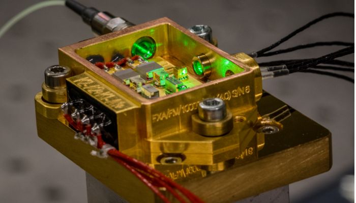
Instruments 2019, 3, 25                                                                          2 of 13

     Sojourner was the first rover to navigate on Mars, which it reached in July 1997 through the
NASA Mars Pathfinder mission [4]. It was followed in 2004 by Opportunity and Spirit, who provided
confirmation of the past presence of water on Mars. The communication was lost with Spirit in 2010
while Opportunity remained active until the beginning of 2019 [5].
     Curiosity landed on Mars in 2012 and is the only rover still active on Mars’ surface [6]. Its main
achievement has been finding evidence of a past habitable environment such as methane and organic
compounds. The European Space Agency (ESA) also sent the Schiaparelli lander as part of the ExoMars
mission in 2016. It crashed on the surface but was successfully able to transmit important data during
its descent which will enable successful landing of the Rover in the second half of the mission [7].
Indian missions have reached orbit but not yet the planet, while Japan and China have also tried to
reach Mars, albeit unsuccessfully to date. Both NASA and ESA have a mission to Mars planned for
2020 (Mars 2020 and ExoMars respectively).
     One of the key objectives of Martian exploration is to explore the possibility of past, present or
even future life on Mars in order to understand the evolution of our planet and to plan future manned
missions to the Red Planet. To do so, different spectroscopy approaches are being used. The laser
devices sent (or planned on being sent) use different design and scientific approaches specific to the
mission requirements and budgeting.

2. Martian Lasers

2.1. Specific Scientific Lasers for Mars Exploration
     In 2011, NASA sent the Curiosity Rover to Mars, which contained the ChemCam instrument,
which is capable of analysing the composition of rocks and soils samples up to 7 m away.
The ChemCam used the laser-induced breakdown spectroscopy (LIBS) technique, with a pulsed laser of
≥10 MW/mm2 power density that vaporized selected targets, and a spectrometer device to characterise
the generated plasma. The ChemCam laser emitted optical pulses at 1067 nm thanks to three
Neodymium-doped Potassium-Gadolinium Tungstate (Nd:KGW) crystals pumped independently by
three 700 W diode stacks. The lasers had an approximate mass of 600 g. The LIBS approach allowed
the ChemCam instrument to analyse the Martian surface samples but not to detect low presence of
organic molecules [8].
     The next NASA Mars mission, to be launched in 2020, will implement improved research devices
compared to those used in the Curiosity rover. The SuperCam, the successor of the ChemCam, can not
only perform LIBS but also Raman spectroscopy in a range up to 12 m away from the rover, to search
for organic compounds. The SuperCam laser (manufactured by Thales) uses a Neodymium-doped
Yttrium Aluminum Garnet (Nd:YAG) crystal instead of a Nd:KGW crystal. It emits two different
laser beams, one at 1064 nm for LIBS spectroscopy, and its frequency-doubled signal (532 nm) for
Raman spectroscopy [9]. Moreover, the NASA 2020 mission will implement the Scanning Habitable
Environments with Raman & Luminescence for Organics & Chemicals (SHERLOC) installed in a
robotic arm that uses an ultraviolet (UV) laser to perform proximity Raman. The SHERLOC is built
with a narrow linewidth 248.6 nm laser (∼400 g) generated from a Neon-Copper Transverse Excited
Hollow Cathode laser made by Photon Systems Inc. [10–12].
     The next European Martian mission, the ExoMars mission, will also be launched in 2020.
The instrument used differs from the NASA ChemCam in its capability to analyse Martian samples
extracted 2 meters below the surface, instead of performing distance and surface analysis. The next
ExoMars mission will carry an analytical laboratory, which includes two laser devices [13]:

•     The Mars Organic Molecule Analyser (MOMA) to conduct broad-range searches for
      organic molecules,
•     The Raman Laser Spectrometer (RLS) to identify mineral phases and search for the presence
      of carbon.
Instruments 2019, 3, 25                                                                                    3 of 13

     The MOMA uses a high-power ultraviolet laser emitting at 266 nm to study large molecules,
inorganic minerals and volatile organic molecules with an adjustable irradiance beam between 35 to
250 MW/cm2 . The laser crystal is pumped at 806 nm, resulting in a passively pulsed beam provided
by a Neodymium/Chromium Doped YAG (Nd:Cr:YAG) media. The resulting 1064 nm beam is then
frequency-quadrupled to 266 nm [14]. The designed laser device has a length of 13 cm and a mass of
113 g (pumping diodes and input fibre not included) [15].
     On the other hand, the ExoMars RLS, also operating inside the rover analytical laboratory, aims at
detecting a wide range of organic functional groups, which will help assess which samples should later
be analysed in depth by the MOMA instrument [13]. This laser device is an 808 nm diode-pumped
solid-state laser (DPSSL), intracavity frequency-doubled, and with an output emission wavelength of
532 nm. The laser design basically consists of two twin lasers mounted side by side for redundancy
purposes, two independent laser resonators with ceramic Nd:YAGs as active medium, pumped
by two independent laser-diodes, and two second-harmonic generator (SHG) Beta Barium Borates
(BBO) crystals.

2.2. Requirements for the ExoMars Laser
     The 2020 ExoMars rover from the ESA mission to Mars will, with the help of a mechanical drill,
extract samples from the planet subsurface down to a depth of two meters and proceed to their
subsequent analysis [16]. The RLS instrument performs the micro analysis of these samples once they
have been reduced to powder to precisely identify the mineral phases and detect potential organic
compounds. The Raman spectral range goes from 150 to 3800 cm−1 with a spectral resolution of 6 cm−1
below 2000 cm−1 [17]. To perform the Raman spectroscopy, a narrow 532 nm laser with the following
requirements had to be designed and assembled:

•     20 and 35 mW of optical output power,
•     Mass of less than 50 g,
•     Redundant design (two lasers assembled on the same breadboard),
•     Pulse width stability of 30 pm,
•     Irradiance of 0.8 and 1.2 kW/cm2 .

    Moreover, the space mission requires for the laser to withstand the following environmental
conditions [18]:

•     Thermal non-operational range between −60 ◦ C and +70 ◦ C,
•     Vibration and shock as seen in Table 1,
•     Space radiations.

         Table 1. Exomars mission vibration requirements for the laser unit. Table reproduced from [19].

                      Sine        5 Hz            1 g/1 g            In-plane/out-plane
                                 30 Hz           20 g/25 g
                                 100 Hz          20 g/25 g
                    Random   20 Hz to 40 Hz    +6 dB/OCT       In-plane/out plane during 120 s
                              40 to 450 Hz         0.16
                             450 to 2000 Hz    −6 dB/OCT
                                  grms              11
                     Shock       100 Hz            25 g              Performed per axis
                                 200 Hz           1500 g
                                10,000 Hz         1500 g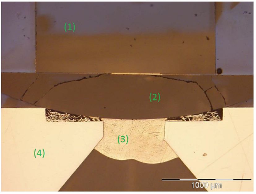
Instruments 2019, 3, 25                                                                                    4 of 13

3. Laser Design and Assembling Method

3.1. Laser Design
      To fulfill both optical and environmental requirements, the final design of the ExoMars DPSSL
developed by Monocrom S.L. (Figure 1) contains commercial CW (continuous-wave) q-mount diodes
emitting at 808 nm from Compound Photonics [20]. Micro-lens fast axis collimators (FAC) from
LIMO GmbH are used to obtain a high energy density on the first millimetre of the laser active
medium, a ceramic Nd(1%):YAG from Baikowski with a front facet HT808 nm and HR1064 nm
(High Transmission and High Reflection; respectively) coating and a back facet HT1064 nm and HR532
coating. This crystal choice allows intrinsically for a narrower output linewidth emission and provides
a better thermal conductivity [21]. The Second Harmonic Generation is performed by a BBO crystal
from Castech Inc with HT1064&532 nm coating on both sides. This material provides a higher doubling
efficiency, lower sensitivity to temperature changes, and higher radiation resistance levels than its
competitors [22]. Finally, a final output mirror made of fused silica with HR1064 nm and HT532 nm
coatings (Layertech GmbH) is used to complete the cavity.

      Figure 1. Exomars laser drawing with all the components assembled. (1) Pumping diodes. (2) FAC.
      (3) Active crystal. (4) SHG-BBO. (5) Fused Silica (FS) output laser cavity mirror. (6) Folding mirror.
      (7) Lambda half and polarization combiner cube. (8) Folding mirror in front of a power feedback
      photodiode. (9) Pinhole-mirror in front of an autofocus photodiode.

   The optical path of the laser beams after they exit the resonator cavities towards the Martian
samples to be analysed is defined by extra steering optics and a Mini-AVIM fibre from DIAMOND
GmbH [20]. The design includes the following optics:

•     a steering mirror to redirect the laser beam propagation at a 90◦ angle;
•     λ/2 waveplates to shift the laser beam polarization and be able to combine both beams through a
      polarizer cube;
•     a double polarization beam splitter, to steer the laser beam another 90◦ while redirecting 5% of
      the light to a power feedback-control photodiode (in charge of stabilizing the laser output power);
•     a pinhole-mirror element, used to couple both coaxial beams inside the output fiber while
      reflecting the back scattered light from the sample to an autofocus photodiode in charge of
      adjusting the focus of the light onto the Martian sample.

    Environmental Finite-Element-Method (FEM) simulations were performed by our partner
LIDAX and demonstrated that the assembly process did not induce any plastic strain or irreversible
deformation of the breadboards and components [19].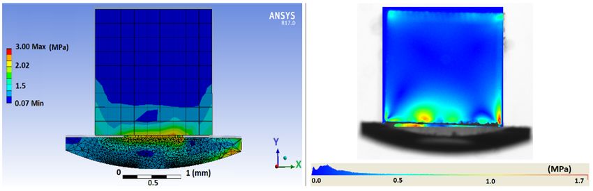
Instruments 2019, 3, 25                                                                               5 of 13

3.2. Assembling Method
      After gathering the RLS device scientific requirements relevant to investigate traces of life in
the Martian subsurface (especially laser wavelength, stability and power) and translating the optical
requirements into a suitable laser design, the next step was to assure that the final assembled laser
could withstand the stringent environmental requirements.
      The selected final Flight Module (FM) for the ExoMars mission is presented in Figure 1. During the
very first attempts, this laser was assembled using adhesive means. The glues (Masterbond UV22 and
Masterbond EP21TDCHT-LO) failed due to their organic composition as, although the laser resonators
could be initially aligned to fulfil the optical requirements, the components became misaligned over
time due to the tensions created by the drying of the adhesive [19]. To overcome this problem,
the assembly method was changed to a low-stress soldering technique called Solderjet Bumping.
Although Solderjet Bumping is considered a low-stress soldering technique, it can eventually provoke
a stress-induced birefringence effect on the soldered laser resonator components (∼mm range) that
could lead to fatal results. For that reason, an intense study to achieve the best soldering approach and
also to minimize the stress-induced birefringence had to be carried out.
      After positioning the Solderjet Bonding capillary (Figure 2) next to the joining geometry, using an
articulating robot arm, the solder alloy is melted by an infrared laser pulse and jetted out of the
capillary by applying nitrogen pressure. The irradiation produces reflow and melting of the solder
alloys. The infrared laser pulse energy is precisely tuned to adapt to the spherical solder preforms’
materials (tin-based lead-free solders, low melting indium alloys or high melting eutectic gold-tin,
gold-silicon, gold-germanium solders, etc.) and diameter [23]. The spherical solder preform diameters
can range from 40 µm to 760 µm. This process is particularly adapted to the soldering of fragile and
brittle materials, such as laser components, thanks to the limited thermal stress applied.

                                 (a)                                    (b)

      Figure 2. (a) Schematic of Solderjet Bumping process [20]. (b) Schematic of the three PVD layer
      system deposited on the optical components with the Solderjet bump bonded on the Au layer (not to
      scale) [20].

    By definition, a soldering process interconnects metallic materials. To solder non-metallic optical
components to the baseplate, lenses and laser crystal facets were coated with a metallic layer by
a physical vapour deposition (PVD) process, obtaining a solderable and wettable surface on the
components. The wetting surface on which the liquid solder droplets can be bonded is produced by
sputtering a three-layer systems using a titanium adhesion layer, a platinum diffusion barrier, and a
noble gold finish to prevent oxidization, as illustrated in Figure 2.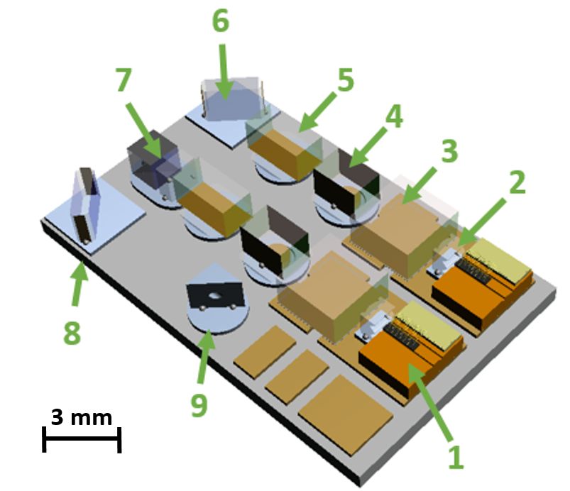
Instruments 2019, 3, 25                                                                            6 of 13

     To compensate for thermal expansion coefficient (CTE) mismatch between the different
components, which can affect the stability of the laser, most of the components were soldered on
KOVAR pads (see grey pads under the components in Figure 1). However, the laser diodes and laser
active medium crystals were assembled over copper pads (see orange pads under the components in
Figure 1) since they have low heat dissipation factors. The copper pads are originally bonded to an
aluminium nitride (AlN) base plate by Curamik. Therefore, some of the copper pads were chemically
removed to be replaced by pre-assembled KOVAR pads at IOF.

4. Laser Assembly Process

4.1. Alignment and Soldering Processes
      A DPSSL is composed by different optical components and materials, which require different
alignment accuracies and assembling methods. When the resonator cavity is short (in our case about
12 mm long), and even more so in the case of an intra-cavity SHG component that has to result
in a narrow line-width output wavelength (30 pm), special attention has to be payed to alignment
and assembly of the components. For the current ExoMars laser, different approaches have been
used, according to the criticality of each component’s alignment. The first differentiation can be done
between the active laser resonator components numbered from 1 to 5 in Figure 1, which need high
alignment resolution, and the passive components numbered from 6 to 9 in Figure 1 which are less
critical in terms of alignment.
      In the first category, we can differentiate between the components which have been soldered
to copper pads for better heat dissipation (pumping-diode and active media Nd:YAG, 1 and 3 in
Figure 1; respectively) and the components without heat dissipation needs (FAC lenses, BBOs and
output mirrors) that have been soldered over KOVAR pads. Once the aluminium nitride (AIN) ceramic
baseplate is prepared with the corresponding copper and KOVAR pads, the components are assembled
according to the different alignment and soldering requirements. The two ceramic Nd:YAGs are
soldered first because YAG is a really strong material [21] and because of its heat dissipation needs.
Fifteen 200 µm AuSn spherical preforms are bumped on their lower sides. Using a Fine Placer device,
the ceramics are then picked, positioned and soldered by applying a thermal ramp of 20 s, 360 ◦ C
and a pressure of 10 N. The Alfalight diodes are then positioned in a similar fashion and soldered
using a Sn95.5Ag3.9Cu0.6 (SAC305) 3.048 mm × 3.048 mm × 0.040 mm preform, which required
applying a temperature ramp up to 240 ◦ C for 10 s. The q-mount die bonding process was performed
at Monocrom s.l.
      For the correct components alignment, we used a reference HeNe laser pointing to the already
mounted Nd:YAG front facet. The HeNe laser was mounted 4.5 m away from the setup and the laser
beam was used for the initial components alignment by overlapping the position of the beam reflected
by each one of the components’ front facet. First, the FAC microlens was aligned, by holding it with a
vacuum gripper and moving it with a Pi Hexapod (F-206 Physik Instrumente GmbH) with a ±2.5◦
angular travel range in all 3 rotational degrees-of-freedom (DOF) and a resolution of 0.0001◦ .
      Next, the SHG-BBO and the output mirror were aligned. Their alignment resolution is very
critical (0.001◦ ) so a fused silica semi-spherical component is previously soldered to them to provide
smooth movement, increased stability and improved precision. Achieving the smallest spacing
possible between the components and the KOVAR pads (10 µm) allows possible tip and tilt alignment
(Figure 3) [23], and provides better control for the alignment and reduced movement during the actual
soldering. The components were aligned and soldered onto their respective KOVAR pads by using two
different Pi Hexapods (Figure 4). In this case, and because of the system capabilities, the AIN baseplate
was flipped upside down and the components soldered by applying Solderjet Bumps through the AIN
backside. The resulting assembly is seen in the components cross-section in Figure 5.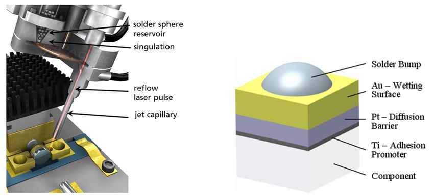
Instruments 2019, 3, 25                                                                                    7 of 13

      Figure 3. Misalignment study due to alloy shrinkage depending on a semi-sphere base radius (yellow)
      and KOVAR pad hole diameter (blue) [24]. The soldering alloy SAC305 is ejected onto the semi-sphere
      and the KOVAR pad though the pad conical aperture.

                                   (a)                                     (b)

      Figure 4. (a) Two Pi Hexoapods have been used to align the BBO and output mirror. Vacuum gripers
      were used for that purpose. (b) Detailed image with the two components being positioned after the
      Nd:YAG and on their respective KOVAR pads.

      Figure 5. Cross section of an output mirror after soldering. (1) Output mirror pre-soldered to the (2)
      semi-spherical body made of fused silica and (3) soldered by a 760 µm SAC305 alloy to the (4) KOVAR
      pad. All the components have been locally metallized with Ti/Pt/Au layer on the areas that have to
      be bonded.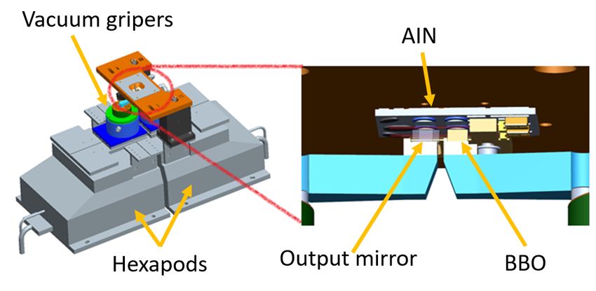
Instruments 2019, 3, 25                                                                                      8 of 13

     Once both redundant laser resonators have been aligned and soldered successfully, both beams
had to be propagated towards the coupling optics and into the output fiber. The steering optical
components (6 to 9 in Figure 1), which do not require heat dissipation, were soldered 30 µm over the
KOVAR pads by using 300 µm SAC305 bumps.
     Each of the different laser material components requires different soldering parameters for a
correct Solderjet Bumping soldering process. The necessary energy needs to be applied in order to
reflow the soldering alloys without damaging the optical components, while guaranteeing solder
robustness at the joints [25,26]. The Solderjet Bumping parametrization energy study results are
summarized in Table 2 where the different spherical preform sizes to bond the optical materials BBO,
YAG and FS to the different substrate materials KOVAR and copper are shown.

      Table 2. Solderjet Bumping energy necessary to reflow and melt the spherical preform alloys of different
      sizes for subsequent bonding of the different combinations of optical and substrate materials.

                                         300 µm Bump        400 µm Bump      760 µm Bump
                                          Energy (mJ)        Energy (mJ)      Energy (mJ)
                          BBO/KOVAR            150                205             389
                          YAG/Copper           217                232             398
                           FS/KOVAR            217                232             441

     Validation of the final assembled components was achieved by performing push tests using a
Zwick Roell Z020. The devices successfully passed equivalent mechanical load tests (Table 1) required
by the mission specifications [18].

4.2. Stress Analysis
     The obvious potential consequence of the soldering approach, and more specifically the
application of thermal energy to reflow the soldering alloys, is the generation of a crack or even
material abrasion inside the optical components. However, this was thouroughly studied during the
solderjet bumping laser parametrization process (results in Table 2), in order to avoid such damage on
the components. Even more, we created a stress analysis process using different softwares; ANSYS to
analyze the mechanical created stress and VirtualLab Fusion to later import the stress analysis and
identify whether the light propagation was affected by stress-induced birefringence effects [27].
     The induced stress could create a component birefringence effect that can be explained through
changes in the component reflective indexes by the following equation:

                                               Bij = B0,ij + 4 Bij ,                                             (1)

where the second-rank tensor B0,ij represents the free-of-stress indicatrix tensor, and 4Bij represents
the indicatrix changes produced due to induced stress, which can also be expressed as,

                                                 4 Bij = π ijkl σkl ,                                            (2)

where the fourth-rank tensor π ijkl is the piezo-optic constant tensor for each material, and σkl is the
second-rank tensor for the stress measured in ANSYS. The stress simulations in ANSYS were moreover
compared with experimental stress data measured by using a polarimeter device (Illis GmbH) as seen
in Figure 6.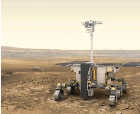
Instruments 2019, 3, 25                                                                               9 of 13

                              (a)                                           (b)

      Figure 6. (a) Soldering-induced stress applied on components simulation results (ANSYS). (b) Real
      created stress measured with a polarimeter device after components soldering [20].

    Once the resulting birefringence was calculated by obtaining Bij , we could calculate the dielectric
constant tensor eij with,
                                           [eij ] = [ Bij ]−1 ,                                      (3)

     eij was later imported in VirtualLab Fusion software, which was used to analyze the effects on the
different laser wavelength propagation’s across the stressed laser materials. The VirtualLab Fusion
results helped to understand if the laser beam was affected due to the stress on components because of
the soldering packaging processes [28].

5. Results
      The final choice of solder material was: 6 mg of AuSn to solder the ceramic Nd:YAGs and
12 mg of SAC305 for the rest of the optical components [19]. Due to the short length of the resonator
cavity (around 12 mm), the alignment of the SHG-BBO and the FS output mirror were the most
critical. We were able to solder these components with a precision of 0.001◦ through the use of
Hexapod PI instruments and specifically customized and manufactured vacuum grippers (Figure 4);
which represented a final success on the components assemble. The final laser assembly is presented
in Figure 7.

                                 Figure 7. Resulting soldered laser assembly.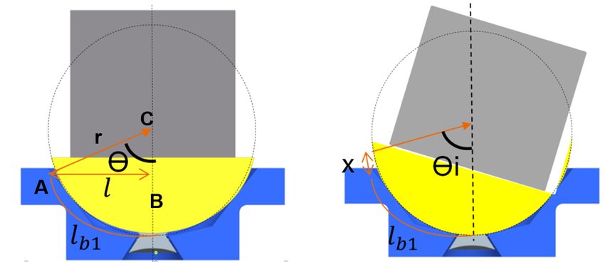
Instruments 2019, 3, 25                                                                                 10 of 13

     An experimental stress analysis was performed to evaluate the effect of the soldering assembly
procedure on the final laser resonator. A polarimeter device was used to measure the stress suffered by
each component. For instance, the assembled FS mirror shown in Figure 6 shows a stress of 0.1 MP
at the laser beam propagation area (centre of the mirror). Together with the stress results extracted
from ANSYS, we introduced this information in VirtualLab Fusion software using Equations (1)–(3).
After applying new material conditions with the calculated permeability matrix information introduced
in VirualLab, we simulated an Ex -polarized Gaussian 50 µm beam at 523 nm propagating through the
FS component, for which we studied the output beam. A value of 0.1% for the beam depolarization
was obtained, which is negligible for the laser optical performance (Figure 8) [27].

      Figure 8. FS mirror output beams for Ex and Ey (depolarization). The scale in the output signal Ey ,
      evidence just a small effect on the beam depolarization from the input beam.

     As seen in Figure 8, the results for a single component hardly showed any influence on the output
beam performance. One could argue however that the sum of the effects for each of the laser resonator
components for the multiple passes through the laser resonator could lead to total non-negligible
birefringence effects. Since such simulation would be more time-consuming than the experimental
evaluation, we continued with the laser assembly process. We can see in Figure 9 that a laser resonator
assembled by the proposed soldering technique achieved a 95.44% Gaussian output beam with the
required power of more than 35 mW at 532 nm. The output beam displayed in Figure 9 was measured
after the FS output mirror.
     The spectra requirements, that could not be achieved when the assembly process was performed
using adhesives, have now also been demonstrated by using the solderJet Bumping-based assembly
process described above, as well as all the optical requirements of the mission [19].

      Figure 9. Results of the laser beam shape measurement 30 cm away from the laser cavity. Assembled
      lasers could achieve a 95.44% Gaussian fit.

6. Conclusions
     The Fraunhofer Institute for Applied Optics and Precision Engineering IOF reports here for
the first time the successful delivery and qualification of the final ExoMars laser designed by the
Spanish company Monocrom s.l. (Figure 10a), according to the mission specifications. Several Flight
Instruments 2019, 3, 25 11 of 13
Module (FM) lasers were delivered in 2017 to the company for optical validation and were later
transferred to the National Institute of Aerospace Technology (INTA), Spain, where they were optically
and environmentally tested. The devices qualified for the Martian mission by achieving the optical
specifications and withstanding the environmental tests performed [19]. One of these devices was
finally mounted inside the Analytical Laboratory Drawer with the rest of the Raman Laser Spectrometer
devices and later qualified by Thales Alenia Space-Italy, to be all finally mounted on the Rosalind
Franklin ExoMars rover depicted in Figure 10b [29]. The next ESA ExoMars mission, which contains the
DPSSL that will help perform the Raman Spectroscopy of underground Martian samples in the search
for evidence of past and present life on the red planet will be launched from Baikonur, Kazakhstan in
July 2020.
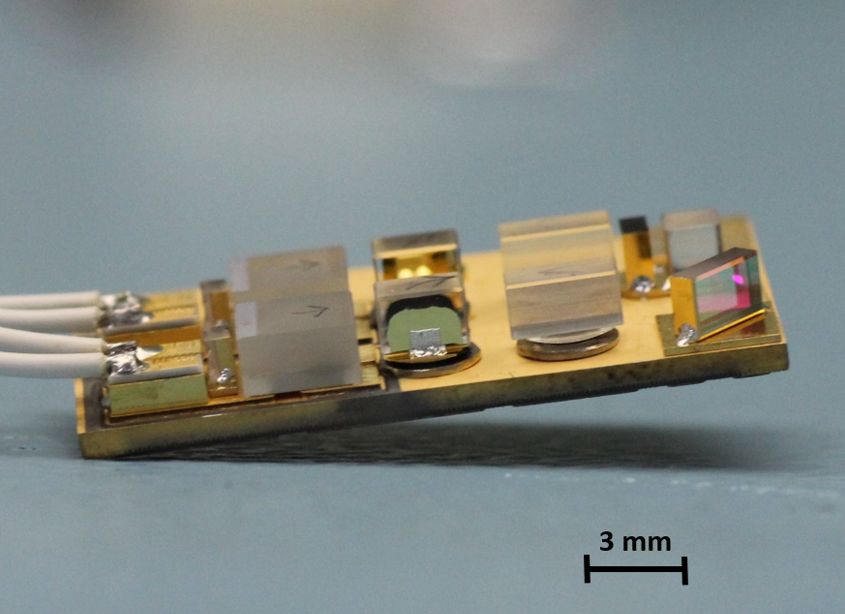
(a) (b)
Figure 10. (a) A final FM assembled laser. (b) Photo: ESA/ ATG medialab. Schematic of the ExoMars
Rover (named Rosalind Franklin) which contains the ExoMars laser [30].
Author Contributions: Conceptualization, P.R.-P.; methodology, P.R.-P.; software, P.R.-P.; validation, M.G.B.;
formal analysis, P.R.-P.; investigation, P.R.-P.; writing–original draft preparation, P.R.-P., M.G.B. and D.G.;
writing–review and editing, P.R.-P., M.G.B. and D.G.; visualization, P.R.-P. and D.G.; supervision, E.B. and
R.E. and A.T.; project administration, P.R.-P.
Funding: The ExoMars Laser Spectrometer is a project funded by Ministerio de Economía y Competitividad
(MINECO), Spain, and supervised and followed by Instituto Nacional de Tecnología Aeroespacial (INTA),
Spain (project AYA-2008-04529). The activities related to the laser assembly were performed under a contract with
Monocrom s.l, Spain, and under the ExoMars project MINECO funding. The rest of test to prove low-induced
stress, components damage or push tests were funded by the Fraunhofer Institute for Applied Optics and Precision
Engineering IOF, and by the Friedrich-Schiller-University of Jena, Germany.
Acknowledgments: The authors want to acknowledge other members of Fraunhofer IOF as well as Robert
Eckardt for the (Figure 10a) and other published elsewhere. The authors also want to acknowledge Monocrom SL,
particularly Miguel Galan, the brain of the laser design, Sergi Ferrando Margalet, Jordi Juliachs for the support
driver and electronics, David Montes for the mechanical designs and Dani Torbisco. Also to Aoife Brady for
double checking the text. Finally to INTA and Fernando Rull for bringing the challenge to us.
Conflicts of Interest: The authors declare no conflict of interest.
Abbreviations
The following abbreviations are used in this manuscript:
NASA National Aeronautics and Space Administration
ESA European Space Agency
INTA National Institute of Aerospace Technology
IOF Institute for Applied Optics and Precision Engineering
USSR Union of Soviet Socialist Republics
LIBS Laser-Induced Breakdown Spectroscopy
Nd:KGW Neodymium doped Potassium-Gadolinium Tungstate
Nd:YAG Neodymium-doped Yttrium Aluminum Garnet
SHERLOC Scanning Habitable Environments with Raman and Luminescence for Organics and ChemicalsInstruments 2019, 3, 25 12 of 13
UV UltraViolet
MOMA Mars Organic Molecule Analyser
RLS Raman Laser Spectrometer
Nd:Cr:YAG Neodymium/Chromium Doped YAG
DPSSL Diode-Pumped Solid-State Laser
SHG Second-Harmonic Generation
BBO Beta Barium Borate
FAC Fast Axis Collimator
HT High Transmission
HR High Reflection
AIN Aluminium Nitride
FS Fused Silica
FEM Finite-Element-Method
FM Flight Module
PVD Physical Vapour Deposition
SAC305 Sn95.5Ag3.9Cu0.6
DOF Degrees-of-freedom
References
1. Journey to the Red Planet: A Mars Missions Timeline. Available online: https://www.space.com/13676-
mars-missions-timeline-history.html (accessed on 28 February 2019).
2. A Brief History of Mars Missions. Available online: https://www.space.com/13558-historic-mars-missions.
html (accessed on 28 February 2019).
3. A Chronology of Mars Exploration. Available online: https://history.nasa.gov/marschro.htm (accessed on
28 February 2019).
4. Mars Pathfinder. Available online: https://www.nasa.gov/mission_pages/mars-pathfinder (accessed on
28 February 2019).
5. Mars Rover Opportunity Is Dead After Record-Breaking 15 Years on Red Planet. Available online:
https://www.space.com/mars-rover-opportunity-declared-dead.html (accessed on 28 February 2019).
6. Curiosity Rover Is Back to Science on Mars. Available online: https://www.space.com/mars-curiosity-
rover-returns-to-science.html (accessed on 28 February 2019).
7. European Mars Lander Crashed Due to Data Glitch, ESA Concludes. Available online: https://www.space.
com/37015-schiaparelli-mars-lander-crash-investigation-complete.html (accessed on 29 March 2019).
8. Ciminelli, C.; Del’Olio, F.; Armensie, M.N. Photonic Sensors and Instruments. In Photoncis in Space, Advanced
Photonic Devices and Systems; World Scientific: London, UK, 2016; pp. 180–185, ISBN 9789814725101.
[CrossRef]
9. Wiens, R.C.; Sylvestre, R.C.; Perez, F.R. The SuperCAM remote sensing instrument suite for the Mars 2020
rover mission: A preview. Spectroscopy 2017, 32, 50–55.
10. Beegle, L.; Bhartia, R.; White, M.; DeFlores, L.; Abbey, W.; Wu, Y.H.; Cameron, B.; Moore, J.; Fries, M.;
Burton, A.; et al. Sherlock: Scanning habitable environments with Raman and luminescence for organics and
chemicals. In Proceedings of the IEEE Aerospace Conference, Big Sky, MT, USA, 7–14 March 2015; pp. 1–11.
11. Solanki, R.; Fairbank, W.M.; Collins, G.J. Multiwatt Operation of Cu II and Ag II Cathode Lasers. IEEE J.
Quantum Electron. 1980, 16, 1292–1294. [CrossRef]
12. Photonsystems. Available online: https://photonsystems.com/space-qualified/ (accessed on 28 February 2019).
13. Vago, J.L.; Westall, F.; Coates, A.J.; Jaumann, R.; Korablev, O.; Ciarletti, V.; Mitrifanov, I.; Josset, J.L.;
DeSanctis, M.C.; Bibring, J.P.; et al. Habitability on Early Mars and the Search for Biosignatures with the
ExoMars Rover. Astrobiology 2017, 17, 471–510. [CrossRef] [CrossRef]
14. Goesmann, F.; Brinckerhoff, W.B.; Raulin, F.; Goetz, W.; Danell, R.M.; Getty, S.A.; Siljestrom, S.;
Missbach, H.; Steininger, H.; Arevalo, R.D.; et al. The Mars Organic Molecule Analyzer (MOMA) Instrument:
Characterization of Organic Material in martian Sediments. Astrobiology 2017, 17, 655–685. [CrossRef]Instruments 2019, 3, 25 13 of 13
15. Kolleck, C.; Buttner, A.; Ernst, M.; Hulsenbusch, T.; Lang, T.; Marwah, R.; Mebben, S.; Priehs, M.; Kracht, D.K.;
Neumann, J. Development of a pulsed UV laser system for laser-desorption mass spectrometry on Mars.
In Proceedings of the International Conference on Space Optics, Rhodes Island, Greece, 4–8 October 2010;
Volume 10. [CrossRef]
16. Perez, C.; Colombo, M.; Díaz, C.; Santamaría, P.; Ingley, R.; Parrot, Y.; Maurice, S.; Popp, J.; Tarcea, N.;
Edwards, H.G.M. Raman laser spectrometer development for Exomars. In Proceedings of the European
Planetary Science Congress, London, UK, 8–13 September 2013; Volume 935.
17. Rull, F.; Maurice, S.; Diaz, E.; Tato, C.; Pacros, A. The Raman laser spectrometer (RLS) on the Exomars 2018
rover mission. In Proceedings of the Lunar and Planetary Science Conference, The Woodlands, TX, USA,
7–11 March 2011; Volume 42.
18. Ott, S.; ExoMars Project Team. Exomars 2018 Mission and System Requirements Document
EXM-M2-RSD-ESA-00003 Issue 1. Available online: http://emits.sso.esa.int/emits-doc/ALENIA/Exomars/
ExoMars_Mission_2018/EXM-M2-RSD-ESA-00003_M-SRD1.0_paper[1].pdf (accessed on 28 February 2019).
19. Ribes-Pleguezuelo, P.; Moral, A.; Basset, M.G.; Rodriguez, P.; Rodriguez, G.; Laudisio, M.; Galan, M.;
Hornaff, M.; Beckert, E.; Eberhardt, R.; et al. Assembly process comparison for a miniaturized laser used for
the Exomars European Space Agency misión. Opt. Eng. 2016, 55, 116107. [CrossRef] [CrossRef]
20. Ribes-Pleguezuelo, P. Low-Stress Soldering Process to Assemble Highly Stable and Miniaturized Laser
Resonators. Ph.D. Thesis, Faculty of Physics and Astronomy, Friederich Schiller University Jena, Jena,
Germany, 2018.
21. Yagi, H.; Takaichi, K.; Ueda, K.; Yamasaki, Y.; Yanagitani, T.; Kaminskii, A.A. The Physical Properties of
Composite YAG Ceramics. Laser Physics 2005, 15, 1338–1349.
22. Gilaberte-Basset, M. Miniaturized Frequency Doubled DPSS Laser Soldered for Space Applications.
Master’s Thesis, Universitat Politécnica de Catalunya (UPC), Barcelona, Spain, 2014.
23. Beckert, E.; Oppert, T.; Azdasht, G.; Zakel, E.; Burkhardt, T.; Hornaff, M.; Kamm, A.; Scheidig, I.;
Eberhardt, R.; Tünnermann, A.; et al. Solder Jetting—A Versatile Packaging and Assembly Technology for
Hybrid Photonics and Optoelectronical Systems. In Proceedings of the IMAPS 2009, 42nd International
Symposium on Microelectronics: Bringing Together the Entire Microelectronics Supply Chain! San Jose, CA,
USA, 1–5 November 2009; Volume 42, pp. 406–412.
24. Kousar, S. Higly Precised Soldering of End Mirrors of a Miniature Diode-Pumped Solid-State Laser for Euopean
Space Ageny ExoMars Mission. Master’s Thesis, Friedrich Schiller University Jena, Jena, Germany, 2014.
25. Banse, H.; Beckert, E.; Eberhardt, R.; Stöckl, W.; Vogel, J. Laser beam soldering—A new assembly technology
for microoptical systems. Microsyst. Technol. 2005, 11, 186–193. [CrossRef]
26. Burkhardt, T.; Hornaff, M.; Beckert, E.; Eberhardt, R.; Tünnermann, A. Parametric investigation of solder
bumping for assembly of optical components. Proc. SPIE 2009, 7202, 720203. [CrossRef]
27. Ribes-Pleguezuelo, P.; Zhang, S.; Beckert, E.; Eberhardt, R.; Wyrowski, F.; Tünnermann, A. Method to
simulate and analyse induced stresses for laser crystal packaging technologies. Opt. Express 2017, 25,
5927–5940. [CrossRef] [CrossRef] [PubMed]
28. Ribes-Pleguezuelo, P.; Septriani, B.; Zhang, S.; Beckert, E.; Eberhardt, R.; Wyrowski, F.; Tünnermann, A.
Solderjet bumping packaging technique optimization for the miniaturization of laser devices. J. Eur. Opt.
Soc. Rapid Publ. 2017, 13. [CrossRef] [CrossRef]
29. ESA. Available online: http://exploration.esa.int/mars/60918-rover-laboratory-inside-test-chamber/
(accessed on 17 April 2019).
30. ESA. Available online: http://www.esa.int/spaceinimages/Images/2017/03/ExoMars_rover (accessed on
28 February 2019).
c 2019 by the authors. Licensee MDPI, Basel, Switzerland. This article is an open access
article distributed under the terms and conditions of the Creative Commons Attribution
(CC BY) license (http://creativecommons.org/licenses/by/4.0/).You can also read